In this article I have explained a simple car tank water sensor alarm circuit using IC 555 and a pulsating signal on the sensing probes to pevent corrosion on the probes. The idea was requested by Mr. Peter.
Circuit Objectives and Requirements
- I couldn't find how to post a project proposal on your website. May be you can help me with this:
- I have searched the web extensively for a "No Water Alarm" circuit to use in my car.
- I want to put a sensor (probes) in the plastic radiator expansion tank that can sound an alarm when it detects no water.
- I can't find anything on internet, only water present alarms or level indicators. Like rain detectors, flooding detectors etc.
- From what I've seen using a 555 timer to create an AC signal to go to the probes is best in order to prevent corrosion due to a DC circuit for the test probes.
- probes go inside expansion tank
The Design
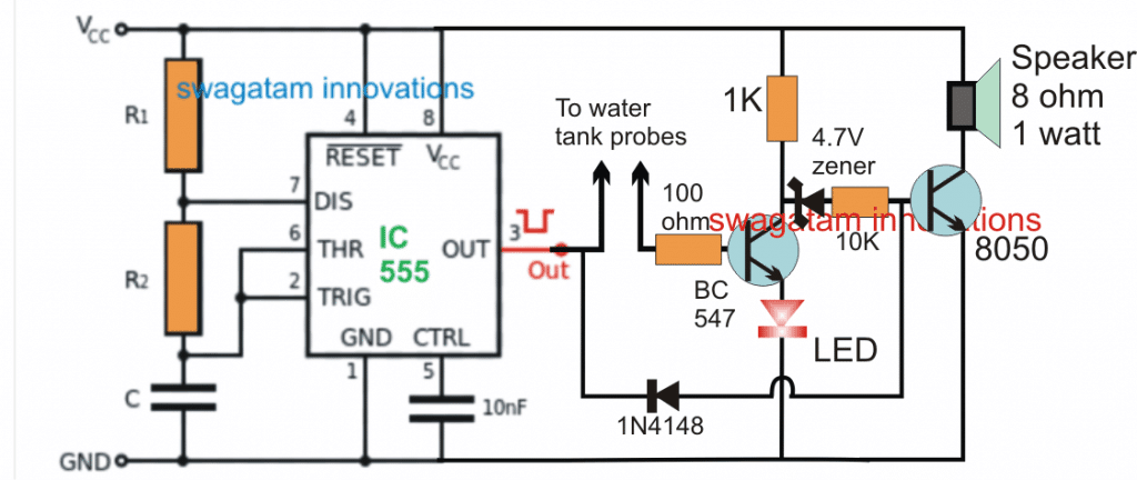
Referring to the figure below, the proposed car tank water sensor circuit can be built using an IC 555 astable design.
Although I am not sure whether a pulsating DC or even an AC signal on the water level sensor probes is able to prevent corrosion in it or not, here we employ the principle as expressed in the above request.
In the design the IC 555 is rigged as an astable multivibrator circuit, at a frequency that may be able to produce the most desirable tone on the connected loudspeaker. This can be experimented by adjusting the values of R1/R2/C connected at pin#2/6/7 of the IC.
The pulsating signal required for the probes inside the car water tank is derived by breaking the base connection of the transistor connected with the pin#3 of the IC. In the absence of water, this transistor remains deactivated, which allows the next transistor to conduct and it sounds the alarm indicating an absence of water in the car tank.
However as soon as water presence is detected, the first transistor now begins getting the base bias through probes due to the water bridging across the probes. This enables the pin#3 transistor to conduct and illuminate the LED at its collector, indicating the presence of water inside the tank.
This action also forces the second transistor to stop conducting, and the speaker tone is halted complementing the LED indication regarding the presence of tank water inside tank.
Circuit Diagram


Questions & Answers
greetings..!!!!
Dear Swagatham,
when we modify the circuit we can use several application.But im facing a problom that when the tank water is full also the buzzer alarming.How we can solve the problom?The circuit was really awesome.
Thank you Dear Sison,
Please do one thing. Please add a 1uF capacitor between the BC547 base and ground, and check the response!
Greetings…!!!!!
Hi Dear Swagatam,
Thanks alot for your express response.Thae 1mf capacitor connected between base and ground didn’t silve the problom.But when i connect collector to positive (across 1k resistance)of bc148 solve the problem forever. Thank you Swagatam.
Thank you Dr. Sison, for updating the results. Glad it is now working for you.
However, adding the 1uF at the BC547 base is the correct way to block the speaker output when water is detected.
You can add the LED in series with the collector 1k of the BC547 and short circuit the BC547 emitter directly with the ground and check again.
greetings…!!!!!
Dear Swagatam,
when i try as per your suggestion its working and no sound from buzzer when tank is full.but when tank is empty the led didnot turnoff completely. please do needful.
You are right Dr.Sison, I completely missed that point.
In that case please try the following modification:
Now its ok Swagatam. Its working smoothly. Also let me know the value of C,R1 AND R2 Value near by IC555.and how can i calculate easily?
That’s great Dr. Sison, You can calculate the values using the following calculator, any frequency that can enable a good audible sound on the speaker should be enough.:
https://www.homemade-circuits.com/ic-555-timer-astable-circuit-calculator/
greetings….
Dear Swagatham,
please let me know the use of 1N4148 in the above circuit.Thank you
Dear Sison,
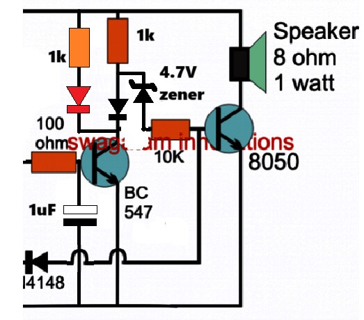
The 1N4148 connection allows the positive supply on the T2 base to be switched ON/OF through the negative oscillating pulses from the 555 pin#3, when there is no water in the tank, which allows the speaker to generate an audible tone.
Thank you sir
Please! the low water alarm does not work; you can’t have 12V/ 1kohm amps constantly flowing into the coolant to ground!!!! just look at how it’s done professionally by the car makers, almost NO current flows into the water ,they use 1 megaohm to 3 megaohm resistors; it would be nice if you could do that with the 555,with a minimum of components; the buzzer is not always needed, an LED is enough.
Hey, it is the concept that’s important, which should be correct! The parts can be modified as required anytime, that’s the fun of electronics. It is all about understanding and customizing.
If you want you use 1M, just connect a 1M in series with the pin#3 probe, and change the BC547 to a Darlingtom pair.
Audio is an added advantage, if you don’t need it you can simply remove the right side transistor, zener, speaker stage
The design was created s per the requirement of Mr. Peter
Good idea,thanks; i’ve had the sensing probe covered with deposits before,rendering it non conductive,when putting 12 volts( and just a few milliamps) on it; more than 2 volts is a problem.
You are welcome, it will need to be implemented through two CMOS gates outputs, oscillating in push pull manner….this push pull method on the probe will prevent the probes from oxidizing, I’ll try to update soon if possible…
Good day Swagatam. I’ve searched extensively to try to rebuild a 5V DC low water alarm control, with no success. I searched your website and found somewhat similar projects, but not actually the same. I hope I’m asking fir your help in the right section, please excuse if I’m wrong.
It uses a float in the water cistern. All was well until a worker during our kitchen renovation knocked this control box of the counter. It dropped, and the audible alarm never worked again.
When the water level dropped to a pre determined level, an led would light, the audible alarm would sound, and you could then press the button and cancel the alarm, but the led would remain lit. When the cistern was filled again, the led would go out until the level dropped again turning the led and alarm back on until you would again cancel the audible alarm until the tank was again filled.
I’ve tested the speaker, tested the continuity of the switch when depressed and both were good. Only component left is the transistor. I am a retired automotive tech, and have never worked with transistors before, and hope you can help me. I ordered I believe a 547 transistor ( if I remember correctly ), soldered it in place and still cannot get the speaker to sound when level is low and led is on.
It is quite possible I didn’t have the transistor oriented correctly to wire this the right way. I found very few distinguishing marks on either new or old to make sure this was right.
Are transistors quite likely to fail from a counter 32” high fall ?
Thank you in advance for your consideration and hopeful help,
Henry
Thanks Henry, a modern day transistor will not fail even if it is dropped from the sky, it cannot fail unless it is hammered or heated over 125 degrees Celsius or subjected to over voltage or current.
I am finding it difficult to suggest a solution since I do not know the circuit details of your unit.
Hi. Thank you for replying. I will get some pictures and draw up some diagrams of it next week. I am somewhat relieved to now learn of the reliability of the transistor. I just can’t guess which component could have failed in that incident.
I will try to get that drawn up and a few pics, mid next week.
Thank you again,
Henry.
Good day Swagatam.
In my drawing of the circuit. The resistors are 4 band: blue/grey/brown….gold. From what I could figure, they are 680 ohms each.
The component I’m assuming is a transistor:
Swag: I tried to post a few pics for you to see, and am unable. Please let me know how I can email you a pic of the diagram I made, and 2 actual pics of 1: resistor 2: the transistor.
Thank you again,
Henry.
Thank you Henry,
Will it be possible for you to upload the image to any free image hosting site, and provide the link to me? I will check the details and try to solve it quickly for you!
Hi Swagatam. I searched a few, and they were from what I could tell, register them pay sites. I’m having trouble finding something equivalent to old photobucket.
Henry
Hi Henry, You just have to search for “Free Image Hosting site” or you can simply upload it to your Google drive, and provide the link to me in the “SHARED MODE”
Hi Swagatam. I haven’t used a free image hosting site before, I will see what I can do. I remember seeing sites like photobucket many years ago, not sure if that’s even an option any more, lol.
I’ll see what I can do and reply back to you.
Thank you again,
Henry
Hi Henry, actually there are plenty such free sites that allow you to keep an uploaded file for some limited amount of time. Yes photobucket used to be a great free hoting site, it seems it is no more free at the moment.
OK, No problem!
Good evening ing Swagatam, I congratulate you on such great electronic projects and I wish you the best of all for your collaboration towards one, excuse me but I would like to make an inquiry, I am assembling the circuit of the automobile tank water sensor circuit in the program Livewire, well it works for me but the transistor 2 remains fixed it does not stop sounding even though the water simulates it, the led if it works well when making the change, I would appreciate if you can help me in this circuit. Greetings.
Hi Joseph, did you try it practically? Please build it practically and you will find that the sound stops when water is detected across the probes.
Still, you can try adding a 10uF capacitor across the base and ground of the left side BC547 and check whether that helps to stop the alarm completely.
Good afternoon, Swagatam, thank you very much for your response. I put the 10 mf electrolytic capacitor and resistance 10 of 10 k if you see that it makes the change to silence the alarm, but it continues to sound but I think it is because the simulator does not It does the function as it is, then I will do it physically, first I have to buy the components if I can get them and at what price, I tell you this because here everything is super but super expensive, well then when I have it ready I will tell you. regards
OK thanks Joseph, please build it practically and check the results…and please post your comment after translating in English, so that I don’t have to do the extra work of translating it.
Ola gosto muito tesse cite
Thanks, Glad you liked it!
thank you dear brother Mr.Swagatam says
I am very happy for the activity you are doing on this page.
I wish you continued health and wellness
Naguib
Thank you dear Naguib
Hi. Thank you. I’m very interested in electronics, but I am still at the beginner’s level and I need to get acquainted with the design of the circuitry step-by-step so that I can design different circuits myself. please tell us If more details are available about the types of circuits and why it was used for our likes. Also, if you send pdf books or useful resources to my email address.
Many thanks
Hi, I appreciate your interest and enthusiasm, however grasping all the minute details can take many years of study and practical experimentation.
Presently I have not prepared an E-book regarding this, although I have been thinking about this since very long. In near future I will surely consider making an E-book for all the interested readers like you.
In the meantime you can consult your doubts and get appropriate answers from me through comments whenever you feel so…
yes I know that, but corrosion can be caused not just by electrolysis, but due to other factors too…
If possible I will try to change the design although that could make the design more complex….