• Skip to main content
  • Skip to primary sidebar

Homemade Circuit Projects

Need circuit help? Post them in the comments! I've answered over 50,000!

Blog | Categories | About | Hire Me | Contact | Calculators-online
You are here: Home / Audio and Amplifier Projects / 3.7 V Class D Speaker Amplifier Circuit for Differential Analog Input

3.7 V Class D Speaker Amplifier Circuit for Differential Analog Input

Last Updated on May 16, 2026 by Swagatam 8 Comments


Table of Contents
  • How it Works
    • Technical Specifications
      • Circuit Diagram

A class D amplifier is basically a category of amplifier in which the power devices (mosfets and BJTs) are operated like switches.

The associated output devices in such amplifier circuits either turn fully ON or fully OFF, but never switch between other undefined levels ensuring minimal heat dissipation and maximum efficiency from the devices.

The working of these amplifier circuits may be understood as follows:

How it Works

An opamp based comparator comes into play whose inputs are fed with two signals, one is the music signal which needs to be amplified while the other is a sample high frequency triangle wave signal.

The opamp is forced to compare and assess the music signal with the sample triangle waves and produce an output which may be assumed to be exactly proportionate and in tandem to the original music signal but in a PWM or a pulse width modulated form.

This music equivalent PWM is further amplified by the adjoining power mosfet or BJT stages in order to reproduce a crystal clear music which may be an exact replica of the fed music and achieved without much heating up of the mosfets.

This allows comparatively lower amps to be consumed than the conventional form of amplifiers coming in other categories such as class A/B/C etc.

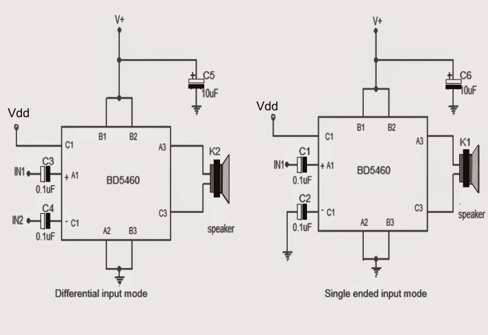
One such IC which is designed to perform a class D type of amplification is the IC BD5460 which does not even require an external choke LC filter for the operations. Usually an inductor filter becomes essential with most class D amplifier topologies for minimizing the accompanied harmonics and similar disturbances.

Technical Specifications

The chip becomes ideally suitable for mini handheld audio devices such as in cellphones, IPods, Ipads, FM radios etc.

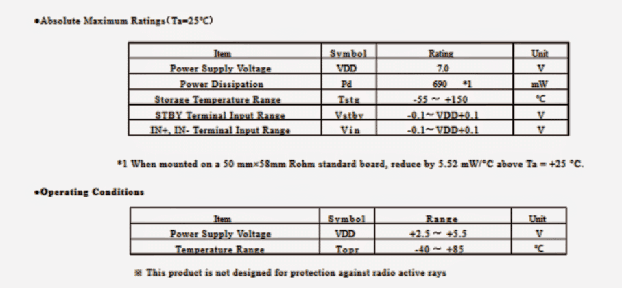
The IC is specified with an output power of about 2 watts at 3.7V. The range of the input power could be from 2.5 V to 6.5 V DC.

The IC also enjoys other built in features like a standby function, short circuit protection, thermal shutdown and under voltage lockout feature.

A couple of class D amplifier circuits using the IC BD5460 can be witnessed in the following diagrams. The left hand side design is differential input based amplifier, while the right hand side depicts a single ended topology. All the 0.1uF capacitors are configured as input decoupling filters.

Circuit Diagram
More info about the IC BD BD5460 may be acquired from the following datasheet of the IC.
You'll also like:

  • parts list for the 40 watt amplifier circuit30 Watt Amplifier Circuit using Transistors
  • DUAL TONE SIREN CIRCUITHow to Make a Dual Tone Siren Circuit
  • pistol bangLoud Pistol Sound Simulator Circuit
  • V shape antennaFM Signal Booster Circuit with Adjustable Gain

Filed Under: Audio and Amplifier Projects Tagged With: Amplifier, Analog, Class, Differential, Input, Speaker

About Swagatam

I am an electronics engineer and doing practical hands-on work from more than 15 years now. Building real circuits, testing them and also making PCB layouts by myself. I really love doing all these things like inventing something new, designing electronics and also helping other people like hobby guys who want to make their own cool circuits at home.

And that is the main reason why I started this website homemade-circuits.com, to share different types of circuit ideas..

If you are having any kind of doubt or question related to circuits then just write down your question in the comment box below, I am like always checking, so I guarantee I will reply you for sure!

Previous Post: « Switching OFF Lights in a Periodic Sequence
Next Post: Cellphone Controlled Car Starter Circuit »

Reader Interactions

Questions & Answers

Total Posts: 8
Newest Oldest
Eric Anderson
May 30, 2023 • 3 years ago #142992

Hi there. Can you use a C9636 ic in lieu of BD 5460? I have a digital radio board that has this ic. I have limited resources and can only use salvaged or harvested components from things I have on hand. and on top of wanting to learn, I really want to hear my music I make on my tablet.

Reply
SwagatamAdmin
May 30, 2023 • 3 years ago #143003

Hi, I cannot find the datasheet of the C9636 for reference, so unable to provide a suggestion.

Reply
brod
August 24, 2014 • 12 years ago #25195

I want to buy power amp ic's ,with o/t power between 4 to 7 watt and cost within 200Rs.so which one can i try?

Reply
SwagatamAdmin
August 24, 2014 • 12 years ago #25211

i have no idea about it, you'll have to check it online…

Reply
Ram
August 22, 2014 • 12 years ago #25159

Is IC BD5460 coming on smd package only ?

Reply
SwagatamAdmin
December 28, 2015 • 11 years ago #37097

Irshad, you can a try an LM386 IC circuit for your requirement, as shown below:

https://www.homemade-circuits.com/2012/08/ic-lm-386-datasheet-explained-in-simple.html

Reply
Irshad Qalandary
December 28, 2015 • 11 years ago #37068

Sir Give me a audio circuit diagram (with 4 inch speaker and headphone jack with usb cable as power option). what components are required to build this circuit.

Reply
SwagatamAdmin
August 22, 2014 • 12 years ago #25169

not sure, please check the info in its datasheet by googling the device number

Reply

Need Help? Please Leave a Comment! We value your input—Kindly keep it relevant to the above topic! Cancel reply

Your email address will not be published. Required fields are marked *

Primary Sidebar

My YouTube Channel

Circuit Simulator: Draw and Simulate Schematics

circuit simulator image

Categories

  • Arduino Projects (95)
  • Audio and Amplifier Projects (134)
  • Automation Projects (18)
  • Automobile Electronics (104)
  • Battery Charger Circuits (90)
  • Datasheets and Components (109)
  • Electronics Theory (151)
  • Energy from Magnets and Earth (43)
  • Games and Sports Projects (11)
  • Grid and 3-Phase (20)
  • Health related Projects (27)
  • Home Electrical Circuits (13)
  • Indicator Circuits (16)
  • Inverter Circuits (98)
  • Lamps and Lights (161)
  • Meters and Testers (72)
  • Mini Projects (28)
  • Motor Controller (68)
  • Oscillator Circuits (30)
  • Pets and Pests (15)
  • Power Supply Circuits (91)
  • Remote Control Circuits (50)
  • Security and Alarm (65)
  • Sensors and Detectors (107)
  • SMPS and Converters (46)
  • Solar Controller Circuits (62)
  • Temperature Controllers (44)
  • Timer and Delay Relay (51)
  • Voltage Control and Protection (44)
  • Water Controller (37)
  • Wireless Circuits (31)

Subscribe to get New Circuits in your Email

Other Links

  • Privacy Policy
  • Cookie Policy
  • Disclaimer
  • Copyright
  • Videos
  • Sitemap

People also Search

555 Circuits | 741 Circuits | LM324 Circuits | LM338 Circuits | 4017 Circuits | Ultrasonic Projects | SMPS Projects | Christmas Projects | MOSFETs | Radio Circuits | Laser Circuits | PIR Projects |

Recent Comments

  • Swagatam on 24V to 12V DC Converter Circuit [using Switching Regulator]
  • Swagatam on Automatic Battery Full Cut-Off Latching Circuit with Trickle Charging
  • Ramin on Automatic Battery Full Cut-Off Latching Circuit with Trickle Charging
  • Joss on 24V to 12V DC Converter Circuit [using Switching Regulator]
  • Swagatam on Simple Capacitive Discharge Ignition (CDI) Circuit

Social Profiles

  • Twitter
  • YouTube
  • Instagram
  • Pinterest
  • My Facebook-Page
  • Stack Exchange
  • Linkedin

Calculators

  • ZVS Induction Heater + Tank Calculator Tool
  • Zener Diode Calculator
  • Wire Current and Thickness Calculator (Ampacity Calculator)
  • Voltage Divider Calculator
  • Transistor Base Resistor Calculator
  • Transistor Astable Multivibrator Calculator
  • TL431 Calculator
  • Solar Panel, Inverter, Battery Calculator
  • Ferrite Core Air Gap Calculator Tool
  • Parallel MOSFET Calculator Tool: How to Connect MOSFETs in Parallel Safely
  • LC Resonance Calculator for EV Battery Charger Circuits
  • LED String Series Resistor Calculator
  • PFC (Power Factor Correction) Calculator Tool: 3kW
  • Passive Power Factor Correction (PFC) Calculator
  • LM567 IC Calculator Tool
  • SMPS Flyback Boost Converter Calculator
  • Shunt Resistor Calculator for Ammeters
  • SCR and Triac Gate Resistor Calculator
  • Battery Back up Time Calculator
  • Boost Converter Calculator (Non-Isolated)
  • Bootstrap Capacitor Calculator
  • Buck Converter Calculator
  • Buck-Boost Converter Calculator
  • Capacitance Reactance Calculator
  • DCM Flyback Transformer & Wire Gauge Wire Size Calculator Tool
  • Filter Capacitor Calculator
  • IC 4047 Calculator (Frequency and PWM)
  • IC 4060 Calculator
  • IC 555 Astable Calculator
  • IC 555 Monostable Calculator
  • IC SG3525, SG3524 Calculator
  • Inductance Calculator
  • Induction Heater Inductor and Resonant Frequency Calculator
  • Induction Heater Work Coil Calculator
  • Inverter LC Filter Calculator
  • LC Resonance Calculator
  • LED Current Calculator
  • LM317, LM338, LM396 Calculator
  • NAND/NOT Gate RC Values Calculator
  • NOT, NAND Gate Frequency Calculator
  • Notch Filter Calculator Tool
  • Ohm’s Law Calculator
  • Phase Angle Phase Shift Calculator
  • Power Factor (PF) Calculator
  • RC Filter Calculator
  • Reactance Calculator
  • Sine Table Calculator for SPWM Arduino Code
  • Small Signal Transistor(BJT) and Diode Quick Datasheet
  • SMPS Calculator for Toroidal Ferrite Transformers
  • SMPS Flyback Transformer Calculator – Design by Target Duty Cycle
  • TL431 Calculator
  • Op-Amp Hysteresis Resistor Calculator

© 2026 · Swagatam Innovations