• Skip to main content
  • Skip to primary sidebar

Homemade Circuit Projects

Need circuit help? Post them in the comments! I've answered over 50,000!

Blog | Categories | About | Hire Me | Contact | Calculators-online
You are here: Home / Audio and Amplifier Projects / Hi-Fi 100 Watt Amplifier Circuit Using 2N3055 Transistors – Mini Crescendo

Hi-Fi 100 Watt Amplifier Circuit Using 2N3055 Transistors – Mini Crescendo

Last Updated on May 15, 2026 by Swagatam 208 Comments

Video Demonstration of the Crescendo Amplifier

The mini crescendo 100 watt transistorized amplifier circuit explained here was built and tested by me and am extremely pleased by its performance and also its ruggedness as far as maintenance and handling is concerned.

Table of Contents
  • Video Demonstration of the Crescendo Amplifier
  • Amplifier Class
  • Circuit Operation
    • How to Set Quiescent Current
    • Power Supply Circuit
      • Parts List of 100 watt amplifier circuit (sh0wn below)

Amplifier Class

Basically, the entire configuration is a symmetrical class A amplifier incorporating an input filter stage, an intermediate driver stage and a powerful symmetrical output stage consisting of the versatile 2N3055 power transistors.

The circuit efficiently drives a 100 watt 4 Ohms speaker with inputs derived from any audio source like a cell phone or DVD player etc.

Before you learn how to build this interesting and useful 100 watt amplifier circuit using 2N3055 transistors, a prior understanding of the involved circuit configuration would be very handy, let’s begin the explanation with the following points:

Circuit Operation

A quick glance at the given circuit diagram makes us conclude that the output configuration is not symmetrical, since the transistors T15 and T16 are both NPN types.

The input stage of the circuit begins or initiates with a symmetrical differential preamplifier stage consisting of the transistors T1, T2 and T3, T4.

T5 and T6 are positioned as the current sources which are further extended as the driver stage consisting of the transistors T7 and T8.

However a closer inspection tells us that of course the wiring is symmetrical, having the transistors T11, T13, T15 at the upper section acting like special booster transistor package.

Similarly the lower section also employs identical super booster stage consisting of the transistors T12, T14 and T16.

The above two sections are perfectly complementary to each other, with reference to the diagram which indicates their emitters being terminated to a common point through the resistors R25 to R27 and via R28 to R30, this effectively that the wiring is exclusively symmetrical by nature.

The output stage is able to produce a massive 200,000 times amplification factor with comparatively very low quiescent current drain.

The quiescent can be set by the adjusting the preset P1.

Due to a non critical nature of the circuit, the entire project can be easily built over a general purpose PCB, however the layout of the components or rather the placement and the ratio of the distance of the components must be kept as identical as possible to the layout of the circuit diagram.

Though a common heatsink may be used for the entire set of the output devices, I personally used separate individual heatsinks for each of the transistors.

This saved me from the headache of using the cumbersome and low efficient mica isolation kit between the transistors.

The inductor is kept for improving the dynamic nature of the circuit. It is built by winding 20 turns of super enameled copper wire over the 1 Ohms resistor itself.

The wire is selected to be close to 1mm in thickness.

Though not absolutely necessary, for better thermal stability the transistors T9 and T11 and also T10 and T12 should be glued together, preferably by attaching the respective pairs face to face.

The quiescent current should be ideally set to 50 mA through the following initial procedure:
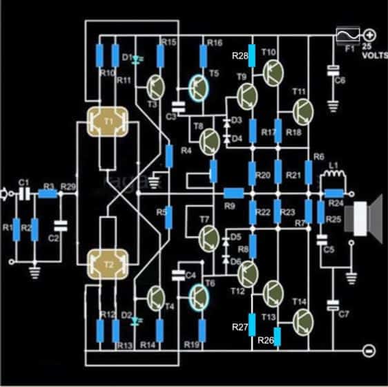
60 watt crescendo amplifier circuit

How to Set Quiescent Current

1) Remove the speakers, and short the input terminals (across R1),

2) Connect a DMM set at current range in series with the positive of the power supply to the circuit,

3) Next adjust the preset such that the meter reads an input of 50mA, that’s all, the amplifier’s quiescent current is set and now the connections may be restored for the normal operations of the system.

Power Supply Circuit

The power supply circuit is also shown along side and as can be seen there’s nothing special about it and may be built using the shown ordinary sets of components.
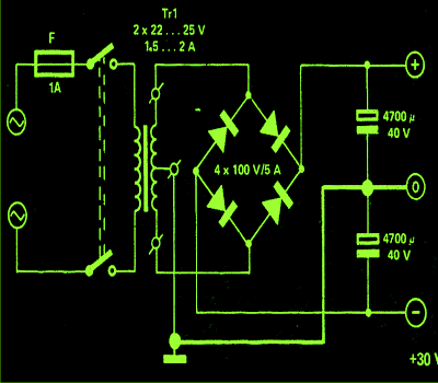
mini crescendo power supply circuit

Parts List of 100 watt amplifier circuit (sh0wn below)

  • R1 = 430 K,
  • R2 = 47K,
  • R3 = 330 Ohms,
  • R4, R5 = 12 K ,
  • R6, R7, R20, R21, R22, R23, R24 = 1 Ohm, 3 Watt, Wire Wound Type,
  • R8, R17 = 68 Ohms,
  • R9 = 100 K, R10, R11, R12, R13 = 5K6,
  • R14, R15 = 12 K,
  • R16, R19 = 100 Ohms,
  • R25 = 10 Ohms / 2 Watts,
  • P1 = 100 Ohms Preset, Linear,
  • C1 = 1 µF / 25V,
  • C2 = 1 n, CERAMIC,
  • C3, C4 = 100PfC5 = 100 nF,
  • C6, C7 = 1000 uF / 35 V,
  • L1 = 20 turns of enameled 1mm copper wire over R24,
  • D1, D2 = RED LED 5mm, All other diodes are = 1N4148,
  • T1 = Matching BC546 pair,
  • T2 = Matching BC556 pair,
  • T3 = BC 557B,
  • T4, T7, T8 = BC 547B,
  • T5, T12 = BC 556B,
  • T6, T9 = BC 546B,
  • T10 = BD 140,
  • T13 = BD 139,
  • T11, T14 = 2N 3055
  • General Purpose PCB,
  • All the transistors T10, T13, T11 and T14 ae mounted on suitable heatsinks

The original design, (courtesy - elektor electronics)
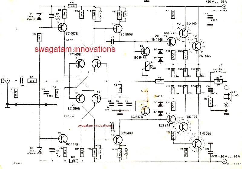
100 watt mini crescendo amplifier circuit

The MOSFET version of the above design can be witnessed in the below given image:
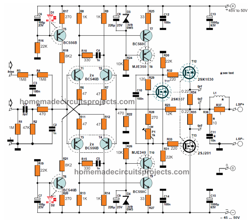
120 watt mini crescendo amplifier circuit

For the complete construction details, please refer to the following link:
Mini Crescendo pdf with PCB and protection circuits 

You'll also like:

  • crystal set amplifier circuit using asingle transistorCrystal Radio Sets with Amplifier Circuit
  • amplifier 25 Simple Preamplifier Circuits Explained
  • Simple AM Radio Receiver using IC TA7642
  • subwoofer circuit mini ground shakerBuild this Subwoofer Amplifier Circuit [Mini Ground-Shaker]

Filed Under: Audio and Amplifier Projects Tagged With: 100, 2N3055, Amplifier, Mini, Transistors, Watt

About Swagatam

I am an electronics engineer and doing practical hands-on work from more than 15 years now. Building real circuits, testing them and also making PCB layouts by myself. I really love doing all these things like inventing something new, designing electronics and also helping other people like hobby guys who want to make their own cool circuits at home.

And that is the main reason why I started this website homemade-circuits.com, to share different types of circuit ideas..

If you are having any kind of doubt or question related to circuits then just write down your question in the comment box below, I am like always checking, so I guarantee I will reply you for sure!

Previous Post: « 3 Glittering LED Christmas Tree Light Circuits Explored
Next Post: 4 Automatic Day Night Switch Circuits Explained »

Have a question or feedback? Feel free to ask below—just make sure it relates to the post above!

Subscribe
Notify of
guest
guest
208 Comments

Primary Sidebar

My YouTube Channel

Circuit Simulator: Draw and Simulate Schematics

circuit simulator image

Categories

  • Arduino Projects (95)
  • Audio and Amplifier Projects (134)
  • Automation Projects (18)
  • Automobile Electronics (104)
  • Battery Charger Circuits (90)
  • Datasheets and Components (109)
  • Electronics Theory (151)
  • Energy from Magnets and Earth (43)
  • Games and Sports Projects (11)
  • Grid and 3-Phase (20)
  • Health related Projects (27)
  • Home Electrical Circuits (13)
  • Indicator Circuits (16)
  • Inverter Circuits (98)
  • Lamps and Lights (161)
  • Meters and Testers (72)
  • Mini Projects (28)
  • Motor Controller (68)
  • Oscillator Circuits (30)
  • Pets and Pests (15)
  • Power Supply Circuits (91)
  • Remote Control Circuits (50)
  • Security and Alarm (65)
  • Sensors and Detectors (107)
  • SMPS and Converters (46)
  • Solar Controller Circuits (62)
  • Temperature Controllers (44)
  • Timer and Delay Relay (51)
  • Voltage Control and Protection (44)
  • Water Controller (37)
  • Wireless Circuits (31)

Subscribe to get New Circuits in your Email

Other Links

  • Privacy Policy
  • Cookie Policy
  • Disclaimer
  • Copyright
  • Videos
  • Sitemap

People also Search

555 Circuits | 741 Circuits | LM324 Circuits | LM338 Circuits | 4017 Circuits | Ultrasonic Projects | SMPS Projects | Christmas Projects | MOSFETs | Radio Circuits | Laser Circuits | PIR Projects |

Recent Comments

  • Swagatam on High Voltage Meter Circuit [for Measuring 10kV]
  • Swagatam on About Me
  • chukwuamaka on About Me
  • Brian Harding on High Voltage Meter Circuit [for Measuring 10kV]
  • Swagatam on Police/Ambulance Siren Circuit with Rotating Beacon Light

Social Profiles

  • Twitter
  • YouTube
  • Instagram
  • Pinterest
  • My Facebook-Page
  • Stack Exchange
  • Linkedin

Calculators

  • ZVS Induction Heater + Tank Calculator Tool
  • Zener Diode Calculator
  • Wire Current and Thickness Calculator (Ampacity Calculator)
  • Voltage Divider Calculator
  • Transistor Base Resistor Calculator
  • Transistor Astable Multivibrator Calculator
  • TL431 Calculator
  • Solar Panel, Inverter, Battery Calculator
  • Ferrite Core Air Gap Calculator Tool
  • Parallel MOSFET Calculator Tool: How to Connect MOSFETs in Parallel Safely
  • LC Resonance Calculator for EV Battery Charger Circuits
  • LED String Series Resistor Calculator
  • PFC (Power Factor Correction) Calculator Tool: 3kW
  • Passive Power Factor Correction (PFC) Calculator
  • LM567 IC Calculator Tool
  • SMPS Flyback Boost Converter Calculator
  • Shunt Resistor Calculator for Ammeters
  • SCR and Triac Gate Resistor Calculator
  • Battery Back up Time Calculator
  • Boost Converter Calculator (Non-Isolated)
  • Bootstrap Capacitor Calculator
  • Buck Converter Calculator
  • Buck-Boost Converter Calculator
  • Capacitance Reactance Calculator
  • DCM Flyback Transformer & Wire Gauge Wire Size Calculator Tool
  • Filter Capacitor Calculator
  • IC 4047 Calculator (Frequency and PWM)
  • IC 4060 Calculator
  • IC 555 Astable Calculator
  • IC 555 Monostable Calculator
  • IC SG3525, SG3524 Calculator
  • Inductance Calculator
  • Induction Heater Inductor and Resonant Frequency Calculator
  • Induction Heater Work Coil Calculator
  • Inverter LC Filter Calculator
  • LC Resonance Calculator
  • LED Current Calculator
  • LM317, LM338, LM396 Calculator
  • NAND/NOT Gate RC Values Calculator
  • NOT, NAND Gate Frequency Calculator
  • Notch Filter Calculator Tool
  • Ohm’s Law Calculator
  • Phase Angle Phase Shift Calculator
  • Power Factor (PF) Calculator
  • RC Filter Calculator
  • Reactance Calculator
  • Sine Table Calculator for SPWM Arduino Code
  • Small Signal Transistor(BJT) and Diode Quick Datasheet
  • SMPS Calculator for Toroidal Ferrite Transformers
  • SMPS Flyback Transformer Calculator – Design by Target Duty Cycle
  • TL431 Calculator
  • Op-Amp Hysteresis Resistor Calculator

© 2026 · Swagatam Innovations