In this post I will show how to construct a wireless DC motor speed control circuit which can be controlled using any IR based remote controller. The proposed project has two main objectives; the first one is 5 step sequential speed control of a 12V DC motor using IC 555 (PWM) and controlling the PWM / speed of the motor fully static / in solid state.
Most DC motor speed control circuits on the internet utilizes some kind of mechanical component such as a potentiometer or a trim pot, but none of them explained how can we control PWM statically, in this post I have explained how can we achieve static control of PWM on evergreen IC 555.
Block Diagram
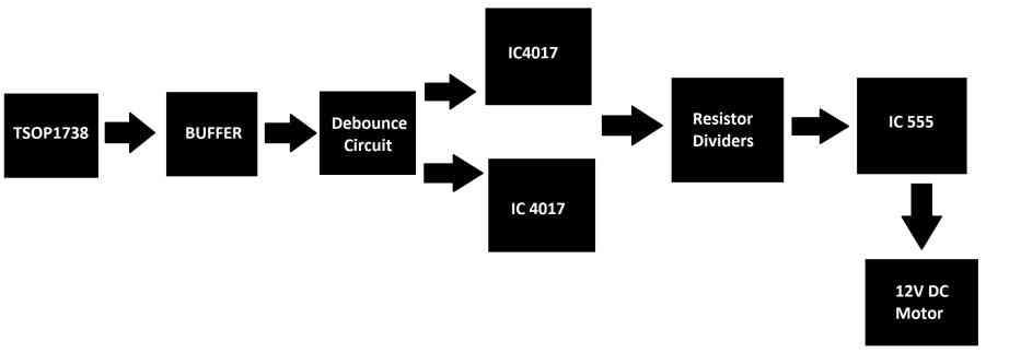
The proposed wireless DC motor speed control circuit project will be based on the above blocks; we will be exploring each of them now.
- The first block is an IR sensor which detects the incoming IR signals from your remote controller.
- The next block is a buffer stage which is essentially an inverting amplifier using a single PNP transistor to output a strong amplified signal and also to prevent loading effect on the detected feeble signal from IR sensor.
- The detected signal is passed to a debouncing circuit which filters surplus pulses and gives out a clean clock pulse to the next stage.
- The next stage consists of a couple of IC 4017s which are responsible for switching the speed of the motor from 1 to 5 (speeds).
- The next stage consists of five resistor dividers which are connected to IC 555; by selecting a resistor divider at a time will control the speed of the motor / PWM.
- The output of the IC 555 is fed to an N-channel MOSFET for efficient speed control of the 12V DC motor.
Now let’s dive in to the circuit diagram and let’s understand actual working of the circuit.
IR Sensor Stage
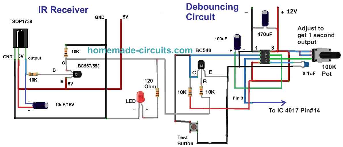
The above circuit encapsulates three stages: the sensor, buffer amplifier and debouncing stage. The circuit utilizes the TSOP1738 IR receiver module to detect the incoming signals from an IR based remote controller.
The signal we received at the output pin of TSOP1738 contains encoded information in the form of narrow and wide pulses, however we don’t need this encoded information but we just need to detect a button press on the IR remote.
To get rid of the encoded signals we have connected a 10uF electrolytic capacitor across the output pin and 5V IN, this will give out a clean pulse.
The output of the TSOP1738 is feeble and needs amplification. To amplify the output of TSOP1738 we have utilized a low power PNP transistor (BC558 / 557). A PNP type transistor has been chosen because the IR sensor outputs “active low” signal and only a PNP type turns ON on “active LOW” signal and also to invert the “active low” signal to “active high” so that the amplified signal is compatible with the next stage.
A pull-down 10K resistor is connected at collector terminal of the PNP transistor so that at idle the output stays LOW. An LED indicator is provided to indicate that IR sensor has received a signal.
The next stage is a debouncing circuit built around IC 555; this circuit gives out one pulse for a predetermined period of time regardless of multiple pluses received by the IR stage. This stage is responsible for giving out a clean clock pulse to the next stage, without debouncing stage the motor speed could jump multiple levels high due to multiple bursts of IR pulses received by the sensor.
The debouncing circuit is nothing but a monostable multivibrator which gets triggered when we apply a LOW signal momentarily to pin #2. The output pulse width or the duration of the output is determined by the resistors and capacitors connected to the IC 555. The formula for calculating the output pulse is as given below:
T= 1.1 x R1 x C1
How, since a potentiometer is utilized in the circuit, you can adjust the output pulse duration using this 100K potentiometer. Our recommendation is to set the output to 1 second, so that any surplus clicks / surplus IR bursts transmitted by the remote will be ignored by the circuit for 1 second. A test button is provided to test / set the output pulse duration.
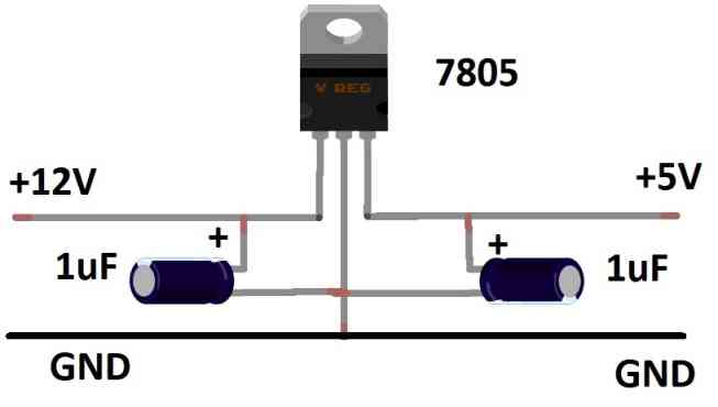
Power Supply
The proposed project uses 12V DC as its power input, but the IR stage works on 5V, so we need to step down the voltage using a regulator circuit as shown below.
This concludes IR reception and filtration stages for the wireless DC motor speed control circuit ; now let’s understand the motor speed control stage.
Wireless PWM Speed Control Stage
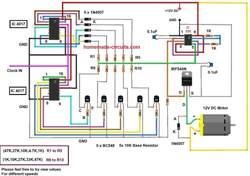
The above circuit is responsible for controlling the speed of the DC motor. Let’s start from the IC 555.
The IC 555 is configured as astable multivibrator, the output pin is fed to an N-channel MOSFET which amplifies the weak square pulses from IC 555 and drives a 12V DC motor. A silicon diode is connected across the motor's terminal in reverse bias configuration to arrest high voltage spikes that arise while switching the motor ON and OFF.
The speed of the motor is controlled by adjusting the duty cycle of IC 555, in other words Pulse width modulation (PWM). The PWM of IC 555 can be controlled applying voltage on “control pin#5".
Please note that by applying a voltage at pin#5 not only changes the duty cycle of the output square wave, but also changes its frequency. We observed frequency shifting from 1 KHz to 10 KHz on our practical setup.
However, as long as the frequency is reasonably well above (say 500 Hz), changes in the frequency will have negligible influence on the speed of the motor and the duty cycle will be the sole factor determining the speed.
The five resistor dividers have different resistor values and selecting a particular resistor divider will apply a unique voltage level on control pin of IC 555, thus different speed levels of the motor can be achieved.
At any given instant only one resistor divider is applied with (+Ve & -Ve) supply and remaining all four resistor dividers remain unpowered, this is achieved by utilizing two IC 4017s, one IC 4017 for five diodes which only allows +Ve supply on upper 5 resistors and another IC 4017 for five NPN transistors only allows –Ve supply to lower 5 resistors.
By applying clock signal at pin #14 of both IC 4017s we can select a resistor divider, thus our desired speed can be achieved. If you want to customize the speed range as per your own preference, then can use the following potential divider formula to fix the resistors. The result will be directly proportional to the PWM output:
Vout (@pin#5) = Lower Resistor / (Upper Resistor + Lower Resistor)
Here lower resistors are R6 to R10, and the upper resistors are R1 to R5.
NOTE: Please note that you can use any fixed resistor values to achieve different rotational speeds, the given resistor values are arbitrary. In our prototype we used trim pots in the place of resistors from R1 to R10 to achieve different speeds.


Comments
How can I add a 2 digits display so that I can see the signals I send from the remote
What do you want to see on the display, the frequency?
what would be the problem if the motor doesnt change the speed of rotation?
If your IC 4017 outputs sequencing in response to the IR pulses on the TSOP sensor?
Thank you! Anyway, do you have a video wherein the circuit actually works, we’re currently having a problem with the switching and the motor doesn’t actually showing any evidence of accelerating or slowing down. The TSOP is working though we can’t confirm if the timer is said to be in 1 second. Lastly, do you have a circuit schematic of the whole thing, if not it’s fine I’m just confused with the last part especially with the resistor dividers. Again, thank you!
I do not have a video, but the above circuit looks correct and should work.
When you toggle the TSOP sensor, each pulse from the TSOP and the 555 monostable must generate a clock pulse on pin14 of the IC 4017.
In response to these clock pulses the 4017 output pins must advance one at a time causing the resistive divider value to change. The changing resistive divider value at pin#5 of the 555 PWM generator should cause a varying PWM at pin 3 of the 555 PWM circuit. These varying PWM outputs from the IC 555 at the agte of the MOSFET should allow the motor speed to vary accordingly.
Another curious question. What if the lower resistors are gone and I directly parallel the upper resistors and connect it to the pin 5 of the 555 timer IC, what would be the effect of it to the circuit?
The lower resistors create resistive dividers along with the upper resistors to create varying values at the pin5 of the IC 555, which in turn creates the required variable PWM to the motor. If the lower resistors are removed there will be no resistive dividers and no variable pWMs and no speed control on the motor.
Hello, I’m stuck searching for a EE senior design project. Do you think there this would be suitable enough to expand on this design? Again, it’s soo much information I just don’t know where to begin. I only have 6 months to complete project, that includes the presentation of it. Any help would be great. Thank you. I wan’t to do something with drives but can’t find too much help so motors is the next best thing.
Hello, if you think the above project will be suitable for you, you can try it, it is a useful project overall.