In this post I have explained 2 simple universal current controller circuits which can be used for safely operating any desired high watt LED.
The universal high watt LED current limiter circuit explained here can be integrated with any crude DC supply source for getting an outstanding over current protection for the connected high watt LEDs.
Why Current Limiting is Crucial for LEDs
We know that LEDs are highly efficient devices which are able to produce dazzling illuminations at relatively lower consumption, however these devices are highly vulnerable especially to heat and current which are complementary parameters and affect an LED performance.
Especially with high watt LEds which tend to generate considerable heat, the above parameters become crucial issues.
If an LED is driven with higher current it will tend to get hot beyond tolerance and get destroyed, while conversely if the heat dissipation is not controlled the LED will start drawing more current until it gets destroyed.
In this blog we have studied a few versatile work horse ICs such as LM317, LM338, LM196 etc which are attributed with many outstanding power regulating capabilities.
LM317 is designed for handling currents up to 1.5 amps, LM338 will allow a maximum of 5 amps while LM196 is assigned for generating as high as 10 amps.
Here we utilize these devices for current limiting application for LEds in the most simplest possible ways:
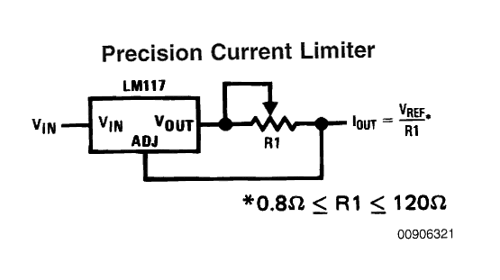
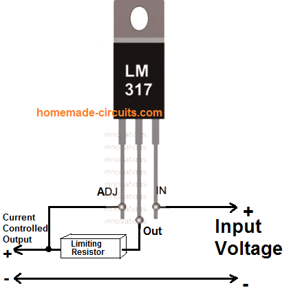
The first circuit given below is simplicity in itself, using just one calculated resistor the IC can be configured as an accurate current controller or limiter.
Calculating the Current Limiter Resistor
The figure shows a variable resistor for setting the current control, however R1 can be replaced with a fixed resistor by calculating it using the following formula:
R1 (Limiting Resistor) = Vref/current
or R1 = 1.25/current.
R1 wattage = R x I2
Current may be different for different LEDs and can be calculated by dividing the optimal forward voltage with its wattage, for example for a 1watt LED, the current would be 1/3.3 = 0.3amps or 300 ma, current for other LEDs may be calculated in similar fashion.
The above figure would support a maximum of 1.5 amps, for larger current ranges, the IC may be simply replaced with an LM338 or LM196 as per the LED specs.
Application Circuits
Making a current controlled LED tubelight.
The above circuit can be very efficiently used for making precision current controlled LED tube light circuits.
A classic example is illustrated below, which can be easily modified as per the requirements and LED specs.
30 watt Constant Current LED Driver Circuit
Assume the LEDs to be 3.3 V, 10 watt, and Supply input to be 12 V
Current of LED becomes = 10 / 3.3 = 3 amps
The LM338 current limiter can be calculated using the formula
R1 = 1.25 / 3 = 0.41 Ohms
Wattage = R x I2 = 0.41 x 3 x 3 = 3.69 watts or 4 watts
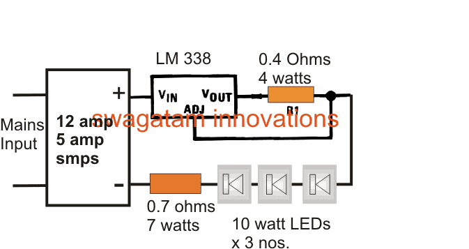
The series resistor connected with the three LEDs is calculated by using the following formula:
R = (supply voltage – Total LED forward voltage) / LED current
R(watts) = (supply voltage – Total LED forward voltage) x LED current
R = [12 - (3.3+3.3+3.3)]/3amps
R= (12 - 9.9)/3
R = 0.7 ohms
R watts = V x A = (12 - 9.9) x 3 = 2.1 x 3 = 6.3 watts
Restricting LED Current using Transistors
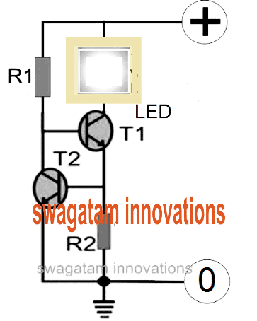
In case you do not have an access to the IC LM338 or if the device unavailable in your area, then you could simply configure a few transistors or BJTs and form an effective current limiter circuit for your LED.
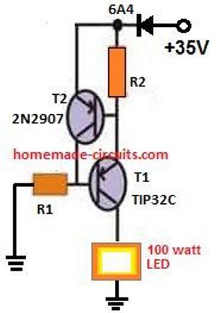
The schematic for the current control circuit using transistors can be seen below. The design is an example for a 100 watt LED current limiter, with 35V as the input supply and the 2.5 amp as the maximum current limit.
PNP Version of the Above Circuit
How to Calculate the resistors
In order to determine R1 you may use the following formula:
R1 = (Us - 0.7)Hfe/Load Current,
where Us = supply voltage, Hfe = T1 forward current gain, Load current = LED current = 100W/35V = 2.5 amps
R1 = (35 - 0.7)30/2.5= 410 Ohms,
Wattage for the above resistor would be P = V2 / R = 35 x 35 / 410 = 2.98 or 3 watts
R2 may be calculated as shown below:
R2 = 0.7/LED current
R2 = 0.7/2.5 = 0.3 ohms,
wattage may be calculated as = 0.7 x 2.5 = 2 watts
Using MOSFET for Higher Current Applications
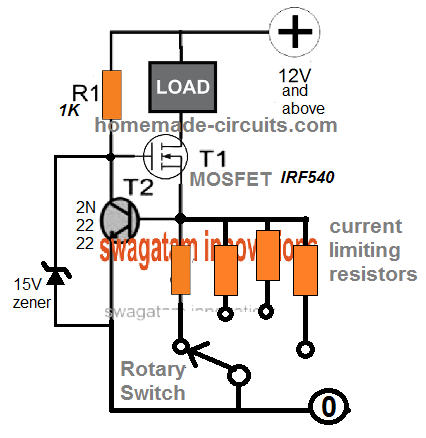
MOSFETs are more efficient than BJTs in terms of handling higher current and wattage. therefore, for applications that require high current limiting, for high wattage loads, a MOSFET can be used in place of T1.
The current handling capacity of the MOSFET will depend on its VDS and IDS ratings, with respect to the case temperature. Meaning, the MOSFET will be able to tolerate the amount of current defined by the product of its VDS x IDS, provided the case temperature does not exceed 40 degrees Celsius.
This may appear practically impossible, therefore the actual limit will be defined by the amount of VDS and IDS that allows the device to work below the 40 degrees Celsius mark.
The above BJT based current limit circuits can be upgraded by replacing T1 with a MOSFET as shown below:
The resistor value calculations will remain the same as discussed above for the BJT version

Variable Current Limiter Circuit
We can easily convert the above fixed current limiter into a versatile variable current limiter circuit.
Using a Darlington Transistor
This current controller circuit features a Darlington pair T2/T3 coupled with T1 to implement a negative feedback loop.
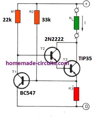
The working can be understood as follows. Let's say the input supply the source current I starts rising due to high consumption by the load for some reason.
This will result in an increase in the potential across R3, causing the T1 base/emitter potential to rise and a conduction across its collector emitter.
This would in turn cause the base bias of the Darlington pair to start getting more grounded. Due to this the current increase would get countered and restricted through the load.
The inclusion of R2 pull up resistor makes sure that T1 always conducts with a constant current value (I) as set by the following formula. Thus the supply voltage fluctuations have no effect on the current limiting action of the circuit
R3 = 0.6 / I
Here, I is the current limit in amps as required by the application.
Another Simple Current Limiter Circuit
This concept uses a simple BJT common collector circuit. which gets its base bias from a 5 k variable resistor.
This pot helps the user to adjust or set the maximum cut off current for the output load.
With the values shown, the output cut off current or current limit can be set from 5 mA to 500 mA.
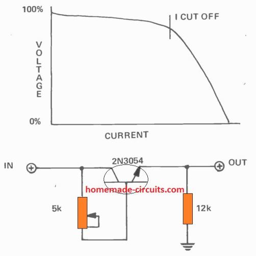
Although, from the graph we can realize that the current cut-off process is not very sharp, yet its is actually quite enough to ensure proper safety for the output load from an over current situation.
That said, the limiting range and accuracy can be affected depending on the temperature of the transistor.
Adjustable Current Controller Circuit using IC 741
The following IC 741-based arrangement can be used if you want a preset current limit which is adjustable across a wide range.
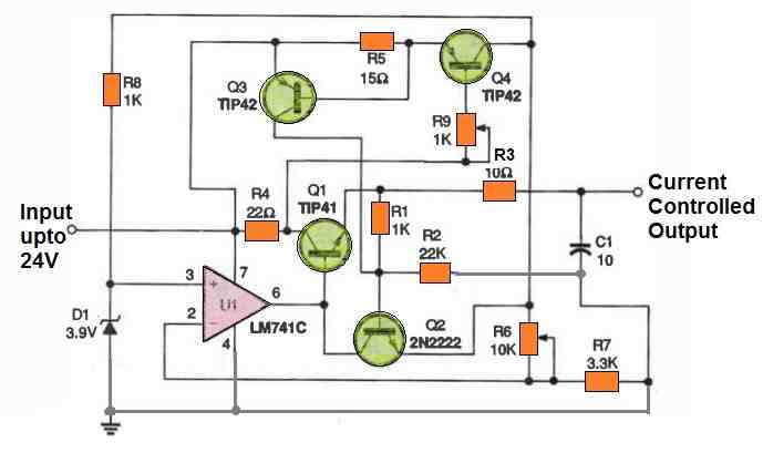
When R9 is adjusted to zero ohms, the lowest current limit for the components depicted is around 47 mA. Add a suitable fixed-amount resistor in series with R9 if you want to set a specific high current limit.
As you can clearly see, implementing current crowbars offers the excellent method of safeguarding electronics from short circuit destruction.


Questions & Answers
Thanks very much Sarunas.
Please refer to the following article and see the diagrams provided at the bottom of the article, you will find the required application:
https://www.homemade-circuits.com/2013/07/making-led-halogen-lamp-for-motorbike.html
Dear sir,
If i am replacing LM117 with LM338 for the application of a battery charger which is supposed to be charged at a rate of 5A maximum, what will have to be the specifications of resistor R?''( Value and wattage ). The transformer current is rated above 20 A at secondary.
And, Will the IC LM338 be able to accept that much current to its input prior to limit it's value???????
Dear Varun,
R = 1.25/5 = 0.25 ohms, wattage = 1.25 x 5 = 6.25 watts
Input voltage should not exceed 30V, as long as this is maintained current won't affect the IC.
Sir can a suitable traic be used to limit high ac current value to a desirable level??
If so, how can it be done????
Varun, you can try this circuit:
https://www.homemade-circuits.com/2013/07/simple-ac-mains-short-circuit-protector.html
Hi Swagatam,
Its nice to read your knowledgable blog, I'm a Street Vendor in Delhi have 7 Outlets as of now and in search of a lighting system for the vending counters.
I Don't have electricity available on the streets hence have to rely completely on Battteries
I'm Currentlky using 80 Watts 1 watt LED Strips that operate with 12 V Battery, But want to increase the lighting to around 400 Watts with minimum powerc onsumption of battery Power.
Reason being the light shave to stay on with full power for around 7 Hours.
I'm Not able to find possible solution to my Problem, would be great if you could help.
Hi anjain
Thanks!
An LED system is itself the most economical lighting option available to date, it cannot be further modified in any manner for getting more than what its been specified at.
But you can ensure that your lights are optimally tuned by employing all the related parameters correctly…. to be precise as discussed in the above article.
If you follow the conditions as explained in the above article you can be sure of having the most efficient system in hand.
I you already have a current controlled circuit in your LED system then the above circuit won't be required.
Dear Sir ,
Will you plz give me materials or link related with power/current limiting ckt . that can be used up to 40 watts which can be used instead of mcb …..as in our market we didn't get the mcb that can meet our requirement (that trip in 40 watts)….I would be grateful if you help me in this project.
You can try the following circuit:
https://www.homemade-circuits.com/2012/05/low-battery-cut-off-and-overload.html
hello. i want to use LM317T IC instead mentioned one. i need 10volt 700mA on output. i have 12v 5A adapter as input. what exactly i need to add or remove? or can you kindly show me another circuit please? i want to run some high watt led. actually 6 of those led at once. LED s are rated 10v and 650mA. please help sir! And thanks for all help.
LM317 will not work, since parallel connection of the LEDs will require 650 x 6 = 3.9 amps.
You will need an LM338 with the first circuit configuration.
For R1 you can use 0.4 ohms, 1 watt resistor
the leds can be connected in parallel at the output, and the input of the IC can be connected with the 12V /5 amp supply.
Ok. ill then use 338. No extra Resistor needed as 2nd schematic (R2) ? like those resistors of led array? also may i know how to determine R1 ? say, if i need to drive those led at 10v and 500mA, what i need to do?
A series resistor could be included as given in the second diagram, however even if it's not included the LEDs would be safe due to R1 which will never allow the current to go beyond the unsafe level.
The formula for determining R1 is given in the article.
Hi, Thanks for all the help. I understand will do the same as you told. Do i need any kind on rectifier or capacitor in the circuit?
If the input is a pure DC no other part would be required for the above circuits…..
Hi Swagatam,
LM317 circuit with power supply of 12v 2amp (or 1.5amp?)- by the explanation I can use 5 nos of 1 watt LED and the resistor required will be: using R1 = Vref/current; or R1 = 1.25/current. we get for 12v 2 amp supply R1 = 1.25/2 = 625 ohms and 2.5 watts (3 Watt resistor)
and for 12v 1.5 amp supply R1 = 1.25/1.5 = 0.833 ohms and 2 watts
for 12v 1 amp supply R1 = 1.25/1.5 = 1.25 ohms and 1.25 watt
Are these calculations correct? I want to use five 1 watt Led's for a start. what is the maximum number of LED's I can use in this circuit all (1 watt). can I make a LED tubelight with this (using 40 of them)
Thanks
Gopal
Hi Gopal,
yes the calculations are correct.
with a 12V/1.5amps output, it can accommodate not moire than 9nosof 1 watt leds, made by connecting 3 strings of 3 leds each in parallel.
for 40 leds you can replace LM317 with LM338
Hi Sir,
I need a simple boost converter….my spec is 12V 35A car battery to 35v 4A & another circuit is same p0wer source 12V 35A to 70V 7A……
Hi Vinu,
you can try the following circuit:
https://www.homemade-circuits.com/2013/03/how-to-convert-12v-dc-to-220v-ac-using.html
Hi Sir,
Does the above link will relate to my requisition…..i want a DC to DC converter from input 12v 35A car battery into output 35v 6A……and also 12v 35A into output 70v 8A…
Hi Vinu,
yes it will, but the involved inductor will need to be made and adjusted by trial and error.
for making the output a DC you can add a 2200uF capacitor at the output.
and also you may entirely remove the BC547 stage along with all the components connected to its base
Hai,
In the above current limiting circuit, the output voltage will be equal to input voltage, Am I right??
I.e. If the input is 12v, 1A means, by a suitable resistor of R1, I can get 12v,700mA.
And can give the input as 5V, 1A to get 5V, 700mA as output in the above circuit??
yes that's correct!
what should be the watts for R1 resistor?? suppose in the above circuit, the input is 12v 1A and the output is 12v 700mA by fixing the R1 as 1.78 ohms. And how to calculate it?
multiply 1.25 by the amps that must not exceed.
for 700mA the resistor wattage sould be 1.25 x 0.7 = 0.87 watts or simply 1 watt
Thankyou sir 🙂
I am having 12v 1A DC adapter. How to convert that to 13.5v 700mA DC?
if it's an smps, you can simply do it by changing one of the resistors at the output section of the circuit.
open it and show me the picture I'll try to figure out the resistor.
…or you can use a 555 boost circuit for achieving the same.
Hai,
with reference of ur 12v 1A smps adapter, I found the last resistor which is connected to the output section in my 12v 1A smps adapter. Can u tell me what resistor value I can replace with that existing resistor???
And am having 12v 5A lead acid battery. how to connect the battery to the below link circuit and what are the modification do i need to obtain 13.5v as output??
https://www.homemade-circuits.com/2013/06/universal-ic-555-buck-boost-circuit.html
These are the images of the 12v adapter. which resistor i have to change to obtain 13.5v?? R2 or R10??
imgur.com/12SdCvS
imgur.com/dFKArEo
Hi, if you want to use a boost circuit then you can try the following design.
Just connect it with your smps, and obtain the required 13.5V across the coil.
You can start with a 10 turn coil over any ferrite core, increase of decrease the turns for adjusting the voltage:
connect a 1uF/25V non-polar cap parallel with the coil
https://www.homemade-circuits.com/2012/09/led-emergency-light-circuit-using-boost.html
…you can try changing the value of D1, try a slightly higher value zeer.
first check what value the existing one is of by connecting a DC voltmeter across its leads, after this you can use a higher one aordingly
…or try increasing the value of R1 for the same
R1 is connected from the output power to the LED. I think i have to change R2 or R10… pls help that which one i have to change.. R2 or R10?? And both the resistor is conected to An IC..
yes R1 is connected to the LEd so it's irrelevant, try R2 or R10, experiment a bit with the two and adjust until the required output is found
Hi Sir,
How U??? I have connected 30x1w leds….3 leds in a string totally 10 strings…..my input voltage is 12v 5amps…..how should i wire up these led arrays to the input source…..aim of the circuit: led should glow at full brightness, less heat generation.
Hi Vinu,
connect 6 ohm 1 watt resistors with each string otherwise your LEDs could burn at 12V.
use the first circuit in the above article in between the 12V and the LED, meaning the 12V must pass through the LM338 circuit before reaching the LEDs.
select R1 = 0.5 ohms 2 watt
Hai, Can u tell me that how u calculated the R1 should be 0.5 ohms, 2 watt in which u replied for Vinu subash?? Bcoz I am also doing LED panels for my home. So need a clarification on calculation.
And am having another two doubts…
Q1:- 1. 10 LEDs of 1 watt each connected in series which require 33v, 350 mA,
2. 10 LEDs of 1 watt each connected in parallel which require 3.3v, 3.5 A.
which of the above two will be more energy efficient??
Q2: 1. A 11 watts CFL bulb require 240v AC,
2. A 40 watts LED panel require 26 v DC.
which of the above two will be energy efficient??
If possible means pls explain..
Hi, the formulas are all perfectly explained in the above article and also in the following articles please go through them:
https://www.homemade-circuits.com/2013/02/make-this-1000-watt-led-flood-light.html
https://www.homemade-circuits.com/2011/12/make-hundred-watt-led-floodlight.html
Hai, thanks for the calculation. Then Am having 13.5v ,1 Amp smps adapter and 12v , 5 Amps battery. The full charge of the 12 v battery will be 13.5 v. I like to connect these both adapter and battery with a relay to the LED panel which consists of three 1watt LED in series. I need a constant 9.9v to the LED panel. what can I do for that?? Is that enough to add a resistor in the series of LEDs?? And If I add a resistor means , can I get a constant input to the LED panel from the smps adapter??
yes, if your 13.5V is almost constant and the ambient heat does not rise by too much then a series resistor and optimal heatsinking will be enough for the LEDs.
if 13.5v drops down there won't be a problem but it must not rise upto 14V or 15V
Thankyou. suppose if my LED panel needs 13.5v and I am having 13.5v dc smps adapter, can I connect the adapter directly to the LED panel or do I need any resistor??
yes it may be done, provided your 13.5V is almost constant and the ambient heat does not rise by too much
Am having 7.5A battery. Need ouput of 700mA. which one I can use?? LM338 or LM196??
use LM317
ok. So for the IC LM317, LM338, LM196, the input Amphere can be anything.
LM317 capable of giving max output of 1.5A. LM338 capable of giving max output of giving 5A. and LM196 capable of giving output of 10A. Am I correct??
input current does not matter, neither will the output consumption, it's the input voltage that must not exceed 35V, rest everything is internally protected for these ICs.
The output capacities that you have mentioned are all correct.
Hai, I designed a circuit like this imgur.com/Xc2J8pl
LED used is 1watt led which need 3.3v, 350mA. I made two strings. Each string consists of two LEDs. Connected two strings in parallel. So the LED bank need 6.6v, 1.4A. Am using 13.5v smps adaptor. Connecting the adaptor to LM7808 to obtain constant 8v, 1.5A. Then connecting the output from the LM7808 to LED string through resistor. so the output from each resistor will be 6.6v, 350mA. I think this will be a constant output. So do I need to add a constant current limiter circuit??
Hi, each string will consume 350mA, not 700mA, the total will be 700mA.
the resistors will take care of the current. for more safety use a common heatsink for LEDs and the 7808 IC this will prevent the LEDs from getting too hot.
Thankyou… So no need of current limiter circuit. The circuit which I designed is enough for constant voltage and current. Am i correct??
yes that's correct, it should be done as suggested in the previous comment.
I want input voltage to be 230v DC and have 7 x 100w led. What can i do?
please specify the LED voltage rating..
100W 32V LED
i'll let you know soon…
an smps converter with 220V to 220V/3amp rating would be required for your application, nothing else looks suitable or safe…
you can modify the output winding of the following design to obtain 220V at the output.
you can remove the opto and the zener network entirely and use the secondary winding directly with your LED after rectification. The LEDs will need to be connected in series.
https://www.homemade-circuits.com/2014/03/12v-5-amp-transformerless-battery.html
go on experimenting with more number of turns at the output winding by some trial and error until you are able to get 220V across the output winding…
mosfets like LM7805,7808, 7812 , 78XX series voltage regulators will give constant voltage with max of 1A output. So if I need a constant voltage like 5v, 8v, 12v with more than 1A means wat mosfets I can use??
you can use a transistor parallel with the IC as shown in the following post with calculated resistors as per the shown table.
easy-electronic-circuits.blogspot.in/2012/03/deriving-high-current-from-7805-7812.html
Is Vref always 1.25. If I was to inpute 32 volts would that not change vref?
yes Vref is fixed for all input voltages,
Good work here but I think I misunderstand a little and hope you may be able to clear it up.
I worked out for first cct I needed 10 ohm resistor for R1 which seems very inefficient. Could you point me in the right direction please.
I have a 100 watt high power led I plan to supply 32 volts and 3100 mA. What resistor would you use. Could you provide ohms and wattage of the resistor please so I can reverse engineer your maths for different leds I have. I think I am not understanding Vref. I thought it would change with your voltage but you seem to keep it at 1.25v. Maybe you could clear this up for me. Much appreciated. Regards,
How did you get 10 ohms:) as per my calculations it should be 0.4 ohms and the wattage should be 1.25 x 3 = 3.75 or 4 watts
The resistor is calculated in the following way:
R = 1.25/3 = 0.41 ohms
Yes, I was not understanding the maths. I read the data sheet and kept working on your examples and realised the 1.25 was a constant. Thank you for your reply.
So would I be correct to assume the internals of the IC cause voltage difference of 1.25 volt between Vadj and Vout. Which would then give me 1.25 volts across the 0.41 ohm resistor and supply the load with the input voltage.
Thanks again. Great work!
correct! That's how it's supposed to be…..1.25V across the calculated resistor for achieving the desired current level, and that's why we multiplied 1.25 with the amps for getting the wattage of the resistor.
Thanks!
Great now that all makes sense. But in practice I still am unable to replicate the current using NI Multisim. I have used 32 volt supply 0.36 ohms connected between Vout and adj.
I figure this would give me approx. 3500 mA. But don't know how to insert LM338 into the software as its not there by default and I can't find any instructions that I understand to insert it. It was suggest by NI to use the LM117 but the readings I get are far from what I expected. It may be due to the current limitation of 2A. I still was getting low load voltage and low current with the correct components for a 50 watt load which should be fine the LM117. Oh well.
Thanks for all your help. Really appreciated.
I don't think a simulation would be necessary, simulators are not always correct, it's better to build the circuit and verify the results using a digital multimeter, that would enable you to understand the design practically, tweak it personally and also confirm the final results.
A simulator will only confuse you more.
Hi sir can you tell me what is current generator circuit & current limiter circuit? actually how functioning those for LED driving. I have 24 volt 5 amp supply & 1 watt LED in series 7 no so is it necessary to use current generator or limiter after supply?
Hi Ashok,
your power supply is a current generator.
an example current limiter design is shown in the above article, please read for a detailed view.
current limiter becomes essential when high watt LEDs are incorporated, so it's a must for your application too.
ok sir. I want to used 1 watt LED in 7 no series and 14 no line in parallel total 98 no LED's. Supply is 24 volt 5amp. so how can i connect them?. as you comment above (vinu subhash 20 may) as 6 ohm resistor. Is it use or not? Current limiter circuit is used or not for this my LED bank? if yes how & what no of current limiter circuit is used?
connecting 7 in series for a 24V supply would allow you to avoid and eliminate the resistors for the individual strings, however make sure the voltage from the source never exceeds 24V.
For limiting current you may use the first design given in the article above…..use LM338 for the IC and 0.3 ohms, 1/2 watt for the resistor
hi sir i got it. supply is constant because i use SMPS supply. one another question is 0.3ohm is minimum value? because below 1 ohm thr is no resistor available in local market
Ashoke, use three 1 ohms in parallel, that will give 0.3 ohms almost.
sir i used transformer 9-0-9 which draw total 19.1v AC after that is used LM317T for DC supply. At output i get 24.3v DC constant. I used this supply for 5 1watt ultra bright LED in series along with 6ohm 1 watt resistor. but still i dont get sufficient illumination. As i used total 5 LED in series and 4 in parallel so its 20 LED i used. my question is how we can improve illumination & is it required current limiter circuit in above article in this application.
each LED series will require a 25 ohm resistor, not a 6ohm….may be all your LED sgot damaged and could have become weak.
Use this formula for calculating the resistor
R = Us minus total LED drop divided by led amp
R = 24 – 0.3×5 divided by 0.3 = 25 ohms.
i think above calculation are like this R= (24- (3.3*5))/3= 2.5ohms &
Watt= [ 24- (3.3*5)] * 3=22.5 watt as per your calculation in above article.
in last comment calculation value= R= ( 24-0.3*5)/0.3= 75ohm
so how much value of Resistor value with watt for each string for maximum illumination.
sorry I wrote 0.3 instead of 3.3…the above calculation should be as like this:
R = (24 – 3.3*5)/0.3 = 25 ohms…wattage = (24 – 3.3*5) * 0.3 = 2.25 watts
why you take 0.3 i above calculation? as in above article in above formula LED current is taken 3 amp
when the LEDs are in series the amp will not increase, it will be equal to the single LED amp spec, so here I have taken it as 300mA or 0.3 amps for each of the strings
Hi, Swagatam Majumdar,
I did as you suggested and built the cct but was unable to get the results indicated above. I am hoping you may point out my error.
My supply voltage is 24 volts, IC is LM338T. I=3.78A R=0.36ohms.
Left to right pin out of IC (writing to front) Adj, Vout, Vin.
Resistor connected between Vout and Adj.
As a variation I also tried a 0.8ohm, 0.33ohm and no resistor and get exactly the same values on Vout across the load (100 watt 24v led) as I do with the 0.36 ohm resistor.
The values I get is 19.7 volts and 3.7 amps.
I tried turning my pot up to 28v on the input and that just reduced my current to the load but kept the voltage on the load at 19.7 volts.
Do you have any pointers?
Thanks for your help.
regards
Ok got it work with a different IC. The output voltage is quite a bit lower than the input voltage though. I found winding the input voltage from 20 volts up to 28 volts the output voltage driving the led remained the same at 19.7 volts. The current increased till it hit 24v and started decreasing above 24v. So it seems 24v input would give me 19.7v 3600mA output which was the sweet spot where I could get a max of 70 watt to drive the led. I am not sure why I was limited to 19.7 volts as I would like to drive the led a bit harder. Any ideas? I thought maybe ohms law fixed current and resistance locked the voltage at that level but then I remembered leds don't abide by ohms law.?????
Hi Shane, if the voltage is not going above 19V without the LED connected, there could be something wrong with the IC again or the wiring, if it's happening with the LED connected, remove it and check the same without any load, it should increase to 24V, and that could be considered as normal.
Under any circumstances, the voltage should be on par with the input and current not exceeding the calculated value, without load and with load respectively
The resistor is not supposed to lock the voltage in the recommended configuration, it's specifically designed for controlling current, not voltage.
Everything will abide by Ohm's law, only the way to understand it could change as per the specifications of the particular component
Am I correct in understanding the voltage drop across a led is just a characteristic of that led in relation to the current. So as long as I have the correct current it should be okay because my supply can easily supply enough voltage (Vf). After lots of reading, other web sites indicate that you do not get the voltage out that you put into lm338 as indicated in this post. They state you get somewhere around 4 to 5 volts less making them pretty inefficient and if I understand this correctly the bigger the gap between the input and output voltage the more energy is turned to heat. So finding the sweet spot on the input potentiometer is important to keep things cool and efficient.
The maximum output voltage will be always less than the input voltage by 3 to 4 volts, that’s the problem with all linear ICs.
…yes the device could dissipate appreciable amounts heat at optimum loads, but that's a different issue and could be compensated by applying a heatsink to the device and using sufficiently rated input source.
Dear Mr. Swagatam,
I would like to make a LED driver circuit which consist 4 nos of 10W LED. And to make it compact it is needed to be transformerless. Voltage and current rating of 10W LED is 9-11V and 1050mA respectively. Please suggest me to build it.
Dear Rajib,
you can build the following circuit:
https://www.homemade-circuits.com/2014/03/12v-5-amp-transformerless-battery.html
How do I connect 2 x 10watt LEDs with a LM338?
LED specs: DC Forward Voltage :9V-12 V, Forward Currect: 1050mA.
What will be the values of the two resistors???
Supply voltage is 12V 3 amps
If the input is a 12V supply then you can connect the LEDs in parallel across the output of the first circuit, with a 24V input you will need to connect the LEDs in series and connect their ends with the output of the first circuit.
The resistor value will need to be calculated as instructed
So, R1= Vref / current. So the current for each LED is about 1A, what is the Vref???
it's mentioned in the article, ref = 1.25:
therefore R1 = 1.25/2amps = 0.62 ohms
wattage = 2 x 1.25 = 2.5 watts
the above is for a 12V input
Doesn't this constant current source has a drop voltage of 3V, so the supply voltage needs be 3V higher than the LED voltage??? So, to power a 12V LED, should I use a minimum of 15V power supply? Or if the current is a constant 1A, the LEDs will glow brightly in 9V also?
according to me LM338 series ICs are specified to drop not more than 0.5V across their input/output terminals, can you tell me where did you find the 3V result?
Hello, I made the first circuit shown here. I connected 2 x 5watt LED in parallel to a LM317. The LED run at 12V.
So, from calculation I(LED) =0.4A each.
The resistance value= 1.25/0.8= 1.56 ohms. I connected 3 x 0.5ohm resistors @ 5W. The LM317 heats up a bit, but it is okay with a heatsink, but the LEDs heat up a lot. I measured the output of the LM317 with a multimeter, it shows 12V and 2.3A?? Also the LM317 became very hot when I was measuring the current only. Why is that happening? Is the LM317 burnt out???
P.S.: My power is 12.3V & 3A.
the 3V drop is due to the generation of heat from the IC and not because of the IC internal circuit, but anyway that means a 3V higher input will be required.
how did you measure the output current? It must be done by connecting the ammeter in series with the LEDs, if you connect the meter probes directly to the output terminals then the IC will get shorted and heat up.
The LeDs will need the specified amount of heatsink for cooling, which could be sufficiently large.
LM317 has internal thermal and short circuit protection so most probably it might be still OK, but if it's a duplicate IC then the results could get seriously affected
I measured current using a multimeter, by connecting the same way as when measuring voltage only changing the red wire to the ampere measuring hole. I took the readings from the point where I connect the LED. Can you explain where the 2.3A came from? If it is a current limiter circuit, it should always provide 0.8A whatever the load.
Anyway, is my calculations correct???
Everything okay now, the output is coming 1.2Amps. Previously, perhaps the LM317 had shut down due to overheating. Thank you for your support.
yes even with an output short circuit the current should be limited, not sure how it was showing 2.3 amps, anyway it's good to know that it's working now.
with over heating of the IC the output must shut down to zero.
Got a heating issue with the LEDs. I will run the LEDs at 9V so that the heat will be less as the LEDs will be in a closed chamber.
Will the same circuit run from a 9V power source?
The LM317 (with heatsink) also heats up a lot after few minutes, is it normal or there is any over voltage or over current?