The proposed TV remote jammer circuit can be used for freezing and scrambling all TV remotes under the specified vicinity.
How TV Remote Works
As we all know the fundamental technology used in today’s TV or similar remote controls is Infrared (IR) light.
The IR spectrum of light is invisible to the human eye, but can be identified using a digital camera, video camera and other such relevant gadgets.
Basically the transmitter associated with a IR remote which is also called the handset emits a chain of IR pulses on pressing the particular button over the handset.
The transmitting element inside the handset is normally a light emitting diode fixed at the pointing surface of the handset.
The emitted pulses are assigned with a unique configuration of pulses relevant to the particular button and the sensor circuitry of the receiving unit.
The sensor circuitry inside the receiver, example your TV set is programmed to recognize these unique patterns and trigger the particular requirement over the TV.
Thus the TV remote responds to every different call depending upon the pressing of the particular IR remote handset buttons. However many remote controls also employ near IR light for controlling the assigned appliance. Typically a 940nm wavelength is the preferred one.
This wavelength is unidentifiable to human eyes but easily detected by the relevant receiving devices. In the “eye” of a video camera this IR would appear like a purple visible light ray.
The appliances which require just a single button for the controls, the IR carries signal itself becomes the triggering beam for such units.
However for multifunction gadgets such as TVs DvDs, etc. each IR signal corresponding with the different buttons goes through special processing of the signals before it can reach the receiving gadget sensor.
As an example in TV remote, each button processes the basic carrier IR signal into complex PWM IR beams, this may also be referred to as encoding of the IR beams, so each IR signal relevant to the assigned button of the remote control handset gets encoded with special pulsed information.
When this special encoded IR message reaches the receiving IR sensor, a reverse process is followed inside the receiving circuitry where the signals are decoded and recognized precisely for which function it was assigned.
Thus the coding is “understood” by the receiver and the relevant function is instantly implemented, providing the user with the desired output.
The above data provides us with an interesting idea which is a constructive one, and much complicated.
However a destructive idea of always easier to implement than a constructive idea.
As explained in the above section, processing the IR signal for the various TV remote button can be hugely complicated but to spoil them or rather scramble them can be quite simple and would require an external IR modulated with some irrelevant frequency to the handset frequencies.
A TV remote jammer circuit can be much easier to make than the remote control itself.
And this scrambling or the jamming frequency needs to be much stronger than TV remote IR signal strength.
How it Works
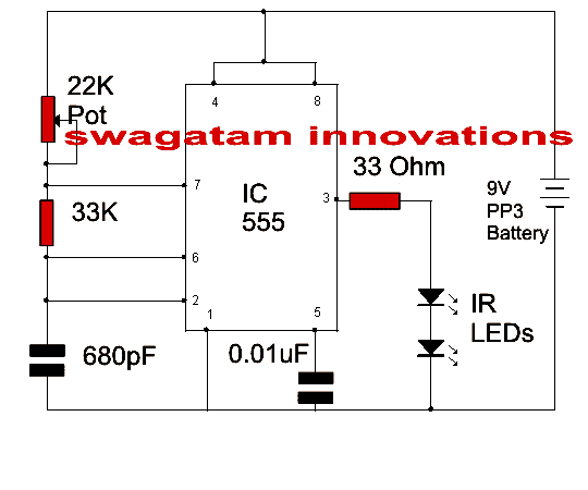
The proposed circuit of a TV remote jammer is basically configured around the popular IC 555 which is arranged in a standard astable mode.
The shown diagram is rather self explanatory. The astable circuit produces a chain of pulses across the IR LEDs which transforms these voltage pulses into strong Infrared radiation all across the ether or the atmosphere.
Any weaker IR wave coming in contact with the above 555 IR wave gets overpowered by it and is scrambled and diffused.
The information stored inside the TV remote signal can be thus jammed or cancelled using this TV remote jammer equipment.
The whole circuit can be built over a small veroboard. The 22k pot should be adjusted for getting the best or the optimal results from maximum possible distance.
The circuit can be operated with a 9V PP3 battery but due to relatively higher current consumption, the cell won't last for much time so a regulated 9V adapter would be more preferable.
By the way for what purpose would you use this? :p
Circuit Diagram


Questions & Answers
Can this circuit be implemented on breadboard?
yes it can be
plz give the pcb layout for this circuit
at what value can i set 22k pot ??
hi,sir 0.01uf OK but
what volt capacitor I use
it's a ceramic disc capacitor, voltage is not important, when the shopkeeper sees "0.01uF ceramic disc" he will understand what to give
Hello sir..
What is the use of two IR LEDs .
Can i use 10k in the place of 22K .
I unable to find out 680 pf capacitior. So plz suggest me another value..
Hello Saurabh, you can try any nearby value, 680pF is not a strict value.
can you make an fm signal jammer?
what kind of signal?
hey Swagatam, I enjoy reading your blog, but i understand a little ! I am a computer hardware engineer, but still i need to know how SMPS PCB can be checked using a digital multimeter, I often get confused with PCB tracks as to where to place the probes and what to check for…is there any answer for me in any of the book, if u know? plz recommend.
Regards
Uzair
Thanks Mohammad!
Every electronic circuit will have a different procedure for its troubleshooting or testing so it's difficult to define specific steps for this. Moreover first it would be important to learn the basics of electronics and then proceed with learning of a particular unit.
for knowing about smps basics, you can refer to this article:
https://www.homemade-circuits.com/2012/03/how-to-understand-switch-mode-power.html