The TSOP17XX series ICs are special infrared sensor devices built for responding to specific range of infrared frequencies and convert it into an electrical pulsed output. It thus features a foolproof immunity to other forms of IR signals.
Due to this specific center or band-pass operating frequency of a TSOP17XX, it becomes difficult to use these sensors for designing a desired or customized frequency based remote control circuits.
In this post we will try to figure out an idea for enabling these sensors to work with any desired unique frequency so that the circuit can be made entirely foolproof.
Basic Working Principle of TSOP17XX Sensor Modules
If we refer to the datasheet of the TSOP17XX IR sensor we find that the IC has some critical operating guidelines to ensure correct and optimal functioning of the sensor in response to an IR signal.
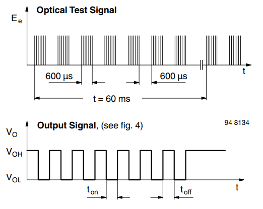
To enable correct functioning of the sensor, the IR signal must be oscillated at the devices's band pass center frequency value, and modulated at bursts of 10 to 70 cycles, with a certain gap after each cycle, as shown in the following image.
The image above clearly shows, that the IR beam from the Tx must be pulsed with the center frequency of the IC which is generally between 30kHz and 39kHx, and modulated with bursts of 10ms gap.
The TSOP responds to this center frequency signal and triggers ON, producing a replicated waveform at its output, wherein the 38kHz are leveled out into bursts of ordinary square wave pulses.
This complex operational waveform ensures increased immunity against many spurious frequencies that may be present in the atmosphere emanated from light bulbs, lke CFLs, fluorescent lamps etc.
Drawback of TSOP17XX Sensors
Although the sensor features a foolproof operation due to this complex signal reception pattern, the fixed center frequency for TSOP sensors restricts their use only to this specific frequency range, making it impossible to create unique customized IR remote control circuits using these chips.
Due to this drawback, a TSOP based remote control system can be usually operated using any common TV or DVD remote control handset, and using any of the buttons on the control unit.
However in electronics there's always a workaround for everything, and for these sensors too we can create a design which will allow us to use the IC with selected unique frequency of our choice so that the receiver is switched only through a particular compatible Tx pair, and not with any available common remote handset.
Designing a Unique Frequency Based TSOP Remote Control Circuit
From the above discussion we understood that a TSOP based sensors require bursts of 38kHz frequency, or the specified center frequency for operating, which indicates that the signal involves two frequencies in which the center frequency is constant but the burst frequency is variable, and not critical.
The idea is to capture this burst frequency in our favor, and use a filter which may recognize this frequency for triggering the output.
The filter circuit can be easily designed using an LM567 tone decoder circuit, and use it for decoding a particular burst frequency from the TSOP sensor output at the receiver side.
The basic concept can be witnessed in the following diagram.
Circuit Diagram
Circuit Operation
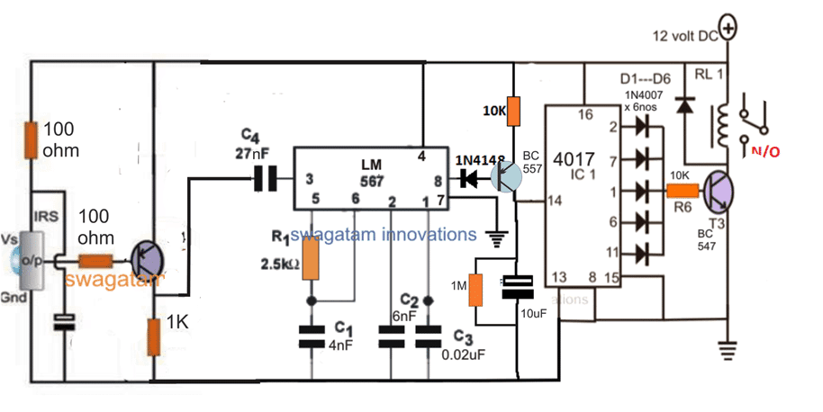
Referring to the above circuit diagram for implementing TSOP17XX with customized frequencies, we see that it consists of 3 basic stages:
the TSOP17XX sensor stage
the LM567 based frequency detector stage
and the IC 4017 based flip flop or bistable circuit stage.
The TSOP17XX stage is configured in its standard mode, which picks up the modulated 38kHz frequency from the transmitter Tx unit and creates a pulsed square wave as indicated in the first diagram.
This output from the TSOP can be expected to carry the burst frequency in which we are interested in. This may be set to 1kHz, 2kHz or anything below 10kHz.
Now we want our LM567 tone decoder stage to detect this modulated frequency correctly, therefore we must make sure that the R1/C1 of the LM567 stage is calculated such that the internal oscillator locks into the same frequency matching the modulation frequency bursts from the TSOP output.
Once these parameters are set we can expect the LM567 to latch ON as soon as the selected frequency is detected from the TSOP78XX output, while any other modulation frequency is simply rejected.
On detecting a correctly assigned frequency, the LM567 output generates a corresponding low trigger signal at its pin#8, activating the attached IC 4017 based flip flop input pin#14 via the PNP.
In this way we are able to assign different unique frequencies ensuring that the receiver triggering is enabled only through the matching Tx handset and not with any common TV remote control unit.
Making the Customized Transmitter (Tx) Circuit
In the above discussion I have explained how a TSOP17XX sensor can be operated with a customized frequency using a frequency detector stage, however this also means that the transmitter (Tx) will also need to be built uniquely for generating the customized IR signals.
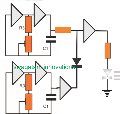
The following figure shows how this may be implemented using a single IC 4049, and a few passive elements:
The 6 gates are all from the IC 4049, R3 can be 10K resistors while the presets can be 100K. The C1 caps will need to be selected with some practical experimentation. The diode can be a 1N4148, remaining resistors may be selected 2K2.
As can be seen the upper pair of gates along with R3, preset and C1 is configured as a free running oscillator, the lower section also has an identical stage.
The upper section is fed to an intermediate buffer gate whose output is finally connected with the transmitter IR photodiode.
The whole section is configured to generate the basic center frequency for the TSOP17XX compatibility which may range from 32kHz to 38kHz depending on the spec of the selected sensor.
The lower oscillator is supposed to be a low frequency modulating stage which can be seen integrated with the upper section through a diode. This low frequency switches the upper high frequency to generate the required "38kHz bursts" on the IR transmitter diode.
This low frequency actually becomes our unique frequency, or the intended customized remote control frequency which needs to be matched with the LM567 frequency so that the both frequencies "shake hands" during the IR communication between the Tx and the Rx units.
The low frequency could be selected from anywhere between 1kHz to 10kHz, and this selected range should be precisely set for the LM567 stage by appropriately adjusting its R1/C1 values.
This concludes our discussion regarding how to modify a TSOP17XX sensor circuit for accommodating customized special frequency ranges or uniquely selected frequency ranges for making the remote control system absolutely foolproof and personal.
If you have any doubts regarding the concept, the comment box is all yours!
I am an electronics engineer and doing practical hands-on work from more than 15 years now. Building real circuits, testing them and also making PCB layouts by myself. I really love doing all these things like inventing something new, designing electronics and also helping other people like hobby guys who want to make their own cool circuits at home.
And that is the main reason why I started this website homemade-circuits.com, to share different types of circuit ideas..
If you are having any kind of doubt or question related to circuits then just write down your question in the comment box below, I am like always checking, so I guarantee I will reply you for sure!
Hi, this is a great article, thank you very much for posting it!
Could this be adapted to become an “InfraRed Frequency Counter” so that it provides the actual “I.R. Modulated Carrier Frequency” like an “R.F. (Radio Frequency) Frequency Counter does?
Wondering how difficult it would be to use a frequency divider network after sniffing coarse RF frequencies, 1-2 mhz, 2-3 mhz 3-4 and so on. Either multiplexing 567’s or using a series of them static awaiting there orders and latching on to switch band pass or low pass filters. I suppose that was your muse, how to convert, have any ideas?
Carlos
#121505
Hello good afternoon Mr. Swagatam, I like this circuit, but I have a question… Can you make the transmitter with an LM555…?
Transmitter idea is already given in the article….
Akinbi Oluwadamilare
#62484
Helo sir,I have been having a serious concern about my area in term of network service from service providers(MTN,Glo).I always have partial or no service at times(weak signal strength).
So I have the idea of creating a signal booster that will help me to correct this situation on ground,but I don’t know the circuit to use.Pls I will be glad if u can give me a circuit to solve this problem.
2) I have a gotv am using,but I relocated from where I was using it and I my new place now, there is nothing like gotv service there .
Is there also any signal booster that can draw the service?
If yes pls provide it for me.
Hello Akinbi, sorry, presently I do not have any mobile network boosting circuit published in this website!
Saqib Lodhi
#53756
Hi Swag,
I’ve read and understood all the circuit and it seems to be a perfect solution. By the way is there any formula or calculation for R1 and C1 calculation. Assume I want to make it on 3kHz. same question for C1 in LM567.
It’s my pleasure Saqib, I knew the formula for calculating the NOT gate oscillator frequency but don’t remember it now, I’ll surely try to investigate it and update soon….however the LM567 formula can be easily found through its datasheet.
Saqib Lodhi
#53752
Thank you Swagatm,
I will try these modifications to my earlier circuit and will let you know the result. once again thank you very much for your effort as a teacher.


Questions & Answers
Hi, this is a great article, thank you very much for posting it!
Could this be adapted to become an “InfraRed Frequency Counter” so that it provides the actual “I.R. Modulated Carrier Frequency” like an “R.F. (Radio Frequency) Frequency Counter does?
Thanks Dante, yes, I think it can be effectively customized to work like an IR frequency counter device…
Any advice on how to go about doing that?
Thanks again!
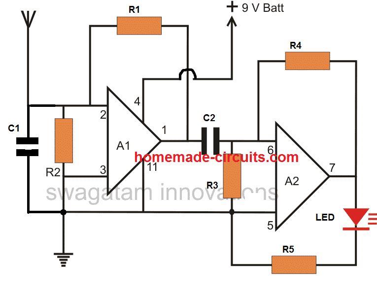
You can try the circuit presented in the following article:
https://www.homemade-circuits.com/lm567-tone-decoder-ic-features-and/
Next, you can remove the 1M pot and configure an IR diode as discussed in the following article:
https://www.homemade-circuits.com/infrared-remote-controlled-door-lock/
Finally, you calibrate the 470k pot given in the first LM567 datasheet, to accurately determine the input IR frequencies..
Wondering how difficult it would be to use a frequency divider network after sniffing coarse RF frequencies, 1-2 mhz, 2-3 mhz 3-4 and so on. Either multiplexing 567’s or using a series of them static awaiting there orders and latching on to switch band pass or low pass filters. I suppose that was your muse, how to convert, have any ideas?
Hello good afternoon Mr. Swagatam, I like this circuit, but I have a question… Can you make the transmitter with an LM555…?
Thank you Carlos, you can try the following design:
Please send me an IR transmitter circuit for this receiving circuit
Transmitter idea is already given in the article….
Helo sir,I have been having a serious concern about my area in term of network service from service providers(MTN,Glo).I always have partial or no service at times(weak signal strength).
So I have the idea of creating a signal booster that will help me to correct this situation on ground,but I don’t know the circuit to use.Pls I will be glad if u can give me a circuit to solve this problem.
2) I have a gotv am using,but I relocated from where I was using it and I my new place now, there is nothing like gotv service there .
Is there also any signal booster that can draw the service?
If yes pls provide it for me.
Hello Akinbi, sorry, presently I do not have any mobile network boosting circuit published in this website!
Hi Swag,
I’ve read and understood all the circuit and it seems to be a perfect solution. By the way is there any formula or calculation for R1 and C1 calculation. Assume I want to make it on 3kHz. same question for C1 in LM567.
It’s my pleasure Saqib, I knew the formula for calculating the NOT gate oscillator frequency but don’t remember it now, I’ll surely try to investigate it and update soon….however the LM567 formula can be easily found through its datasheet.
Thank you Swagatm,
I will try these modifications to my earlier circuit and will let you know the result. once again thank you very much for your effort as a teacher.
Thanks Saqib, I hope it works!!