In this article I have explained a solid state switch-mode mains voltage stabilizer circuit without relays, using a ferrite core boost converter and a couple of half-bridge mosfet driver circuits. The idea was requested by Mr. McAnthony Bernard.
Technical Specifications
Of late i started looking at voltage stabilizers use in house hold to regulate utility supply, boosting voltage when utility low and stepping down when utility is high.
It is built around mains transformer(iron core) wound in auto transformer style with many taps of 180v, 200v , 220v , 240v 260v etc..
the control circuit with the help of a relays selects the right tap for output. i guess you familiar with this device.
I started thinking to implement the function of this device with SMPS . Which will have the benefit of giving out constant 220vac and stable frequency of 50hz without using relays.
I have attach in this mail the block diagram of the concept.
Please let me know what you think, if it makes any sense going that route.
Will it really work and serve same purpose? .
Also i will need your help in the high voltage DC to DC converter section.
Regards
McAnthony Bernard
The Design
The proposed solid state ferrite core based mains voltage stabilizer circuit without relays may be understood by referring to the following diagram and the subsequent explanation.
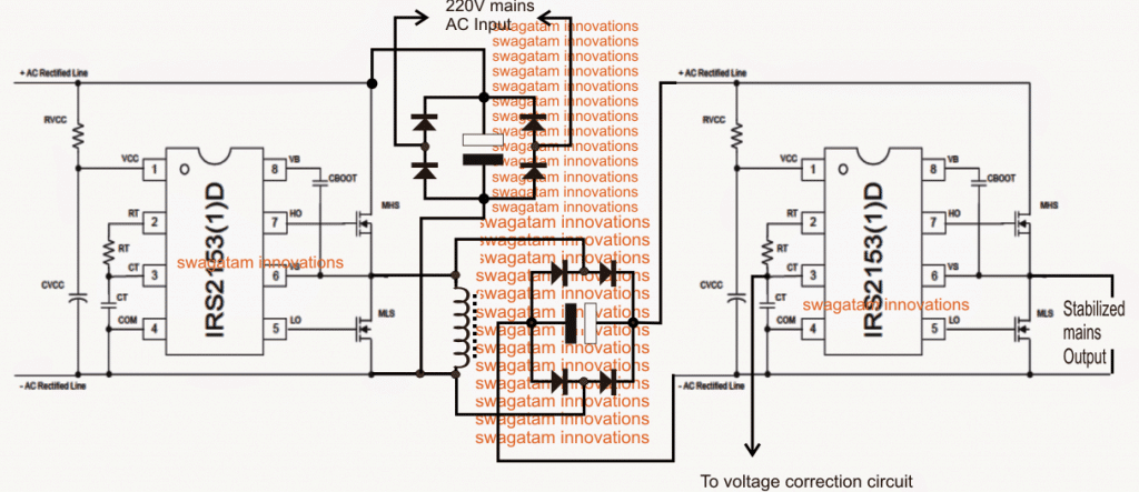
RVCC = 1K.1watt, CVCC = 0.1uF/400V, CBOOT = 1uF/400V
The figure above shows the actual configuration for implementing a stabilized 220V or 120V output regardless of the input fluctuations or an over load by using a couple of non-isolated boost converter processor stages.
Here two half bridge driver mosfet ICs become the crucial elements of the whole design. The ICs involved are the versatile IRS2153 which were designed specifically for driving mosfets in a half bridge mode without the need of complex external circuitry.
We can see two identical half bridge driver stages incorporated, where the left side driver is used as the boost driver stage while the right hand side is configured for processing the boost voltage into a 50Hz or 60Hz sine wave output in conjunction with an external voltage control circuit.
The ICs are internally programmed to produce a fixed 50% duty cycle across the output pinouts through a totem pole topology. These pinouts are connected with the power mosfets for implementing the intended conversions. The ICs are also featured with an internal oscillator for enabling the required frequency at the output, the rate of the frequency is determined by an externally connected Rt/Ct network.
Using the Shut Down Feature
The IC also features a shut down facility which can be used to stall the output in an event of an over current, over voltage or any sudden catastrophic situation.
For more info on this half bridge driver ICs, you may refer to this article: Half-Bridge Mosfet Driver IC IRS2153(1)D - Pinouts, Application Notes Explained
The outputs from these ICs are extremely balanced owing to a highly sophisticated internal bootstrapping and dead time processing which ensure a perfect and safe operation of the connected devices.
In the discussed SMPS mains voltage stabilizer circuit, the left side stage is used for generating around 400V from a 310V input derived by rectifying the mains 220V input.
For a 120V input, the stage may be set for generating around 200V through the shown inductor.
The inductor may be wound over any standard EE core/bobbin assembly using 3 parallel (bifilar) strands of 0.3mm super enameled copper wire, and approximately 400 turns.
Selecting the Frequency
The frequency should be set by correctly selecting the values of the Rt/Ct such that a high frequency of about 70kHz is achieved for the left boost converter stage, across the shown inductor.
The right hand side driver IC is positioned to work with the above 400V DC from the boost converter after appropriate rectification and filtration, as may be witnessed in the diagram.
Here the values of the Rt and Ct is selected for acquiring approximately 50Hz or 60Hz (as per the country specs) across the connected mosfets output
However, the output from the right side driver stage could be as high as 550V, and this needs to be regulated to the desired safe levels, at around 220V or 120V
For this a simple opamp error amplifier configuration is included, as depicted in the following diagram.
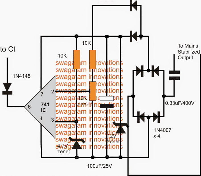
Over Voltage Correction Circuit
As shown in the above diagram, the voltage correction stage utilizes a simple opamp comparator for the detection of the over voltage condition.
The circuit needs to be set only once in order to enjoy a permanent stabilized voltage at the set level regardless of the input fluctuations or an overload, however these may not be exceeded beyond a specified tolerable limit of the design.
As illustrated the supply to the error amp is derived from the output after appropriate rectification of the AC into a clean low current stabilized 12V DC for the circuit.
pin#2 is designated as the sensor input for the IC while the non-inverting pin#3 is referenced to a fixed 4.7V through a clamping zener diode network.
The sensing input is extracted from an unstabilized point in the circuit, and the output of the IC is hooked up with the Ct pin of the right side driver IC.
This pin functions as the shut down pin for the IC and as soon as it experiences a low below 1/6th of its Vcc, it instantly blanks out the output feeds to the mosfets shutting down the proceedings to a stand still.
The preset associated with pin#2 of the opamp is appropriately adjusted such that the output mains AC settles down to 220V from the available 450V or 500V output, or to 120V from a 250V output.
As long as the pin#2 experiences a higher voltage with reference to pin#3, it continues to keep its output low which in turn commands the driver IC to shut down, however the "shutting down" instantly corrects the opamp input, forcing it to withdraw its output low signal, and the cycle keeps self correcting the output to the precise levels, as determined by the pin#2 preset setting.
The error amp circuit keeps stabilizing this output and since the circuit has the advantage of a significant 100% margin between the input source volatge and the regulated voltage values, even under extremely low voltage conditions the outputs manages to provide the fixed stabilized voltage to the load regardless of the voltage, the same becomes true in a case when an unmatched load or an overload is connected at the output.
Improving the above Design:
A careful investigation shows that the above design can be modified and improved greatly to increase its efficiency and output quality:
- The inductor is actually not required and can be removed
- The output must be upgraded to a full bridge circuit so that the power is optimal for the load
- The output must be a pure sinewave and not a modified one as may be expected in the above design
All these feature have been considered and taken care of in the following upgraded version of the solid state stabilizer circuit:
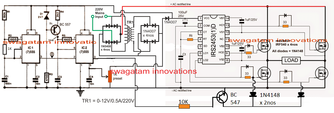
Circuit Operation
- IC1 works like a normal astable multivibrator oscillator circuit, whose frequency can be adjusted by changing the value of R1 appropriately. This decides the number of "pillars" or "chopping" for the SPWM output.
- The frequency from IC 1 at its pin#3 is fed to to pin#2 of IC2 which is wired as a PWM generator.
- This frequency is converted into triangle waves at pin#6 of IC2, which is compared by a sample voltage at pin#5 of IC2
- Pin#5 of IC2 is applied with sample sinewave at 100 Hz frequency acquired from the bridge rectifier, after appropriately stepping down the mains to 12V.
- These sinewave samples are compared with the pin#7 triangle waves of IC2, which results in a proportionately dimesnioned SPWM at pin#3 of IC2.
- Now, the pulse width of this SPWM depends on the amplitude of the sample sinewaves from the bridge rectifier. In other words when the AC mains voltage is higher produces wider SPWMs and when the AC mains voltage is lower, it reduces the SPWM width and makes it narrower proportionately.
- The above SPWM in inverted by a BC547 transistor, and applied to the gates of the low side mosfets of a full bridge driver network.
- This implies that when the AC mains level will drop the response on the mosfet gates will be in the form of proportionately wider SPWMs, and when the AC mains voltage increases the gates will experience a proportionately deteriorating SPWM.
- The above application will result in a proportionate voltage boost across the load connected between the H-bridge network whenever input AC mains drops, and conversely the load will go through a proportionate amount voltage drop if the AC tends to rise above the danger level.
How to Set up the Circuit
Determine the approximate center transition point where the SPWM response may be just identical to mains AC level.
Suppose you select it to be at 220V, then adjust the 1K preset such that the load connected to the H-bridge receives approximately 220V.
That's all, the set up is complete now, and the rest will be taken care of automatically.
Alternatively, you can fix the above setting towards the lower voltage threshold level in the same manner.
Suppose the lower threshold is 170V, in that case feed a 170V to the circuit and adjust the 1K preset until you find approximately 210V across the load or between the H-bridge arms.
These steps concludes the setting up procedure, and the rest will automatically adjust as per the input AC level alterations.
Important: Please connect a high value capacitor in the order of 500uF/400V across the AC rectified line fed to the H-bridge network, so that the rectified DC is able to reach upto 310V DC across the H-bridge BUS lines.


Questions & Answers
Hey want a inverter ckt. At least to drive a tube light and a ceiling fan. Need ur help
do you want a PWM controlled design or just an ordinary type?
Ordinary. Cost is my concern.
you can try this one
https://www.homemade-circuits.com/2012/07/simplest-and-best-100-watt-inverter.html
use a 40AH battery, and use TIP35 in place of 2N3055
Heres a link, check out. Want this radiant energy light procedure
I saw the link, I'll try to design it, and post it soon.
Thanx bro. I thought that fans needs sinewave inverter. Is that design effecient for fan
the fan will not be affected by a square wave inverter, but it might create a slight buzzing noise…you can use the suggested circuit without any issues….
I want to make it automatic, kindly tell me
do you mean automatic changeover from mains to battery mode and vice versa???
Yes, like offline UPS
Actually im gonna sell these units for low power requirement. So im little afraid if it harms the fan.
you can try the following design, this will be quite safe for fans too… once you make it let me know, next I'll tell you how to make the automatic changeover circuit
https://www.homemade-circuits.com/2015/05/simplest-pwm-modified-sine-wave.html
Dear Swagatam, understood the circuit but will it be able to drive an air conditioner? whats the power output of the circuit?
regards
Hi Muhammad,
this is not a VFD circuit, it's a constant voltage AC to AC stabilizer circuit….so it cannot be used like an AC inverter.
will this stabilizer work for my air conditioner? what is its power output?
🙂 no i meant would it be able to stabilize the voltage for air conditioner? sorry for using the word "drive" my mistake
yes it can be used like a voltage stabilizer for any appliance….however in your other email you had asked regarding an AC inverter which is actually a VFD…
Hello Swagatam. I have built this smps stabilizer but the 1k 1w resistor of the left stage is burnig like hell. it burns like bulb anytime the circuit is powered. I have tried to disconnect the inductor and the right stage circuit, still it burns. I used 180uf/400v capacitor to rectify 220vac to 310vdc, at the right stage, I used 150uf/500v capacitor. what might be the problem of the left stage? I really need to build this stabilizer to obtain constant 50hz output. plz help.
Hello afam, if it's the RVCC on the left that you are referring to, you can try increasing its value to 22K 5 watt and see the response, if it still gets hot, keep increasing it until things become under control.
plz sir, have u built and tested this circuit? ia ir2153 same with irs2153 or is any other ic to replace irs2153?
afam, I have not tested it practically, but my mind simulation says it will definitely work if done correctly,
and this is not for the newbies.
yes both the IC variants are one and the same
i am not new in this bcos i have done some of ur projects that i needed and i got them working except this smps volt stabilizer. i believe that this circuit will help my genset output to stay at 50Hz output. what is the left ic pin 1 volt input?
please read this article for more info
https://www.homemade-circuits.com/2013/09/half-bridge-mosfet-driver-ic-irs21531d.html
i need frequency formular plzz.
Hello
I really surprised by your works and intentions to help people,
Now allow me to get to my point,
I need a voltage regulator with these capabilities as possible
1-focus on low voltage problems rather than high voltages preferably around 100v and up to 250v
2-I need it to be capable of starting and sustaining 3.5 ton air conditioner about 30 amps and other design capable of sustaining 5A for lightening.
3-Avoid big transformer as much as possible,I like ferrite transformers
secondary Features
I like it to has an LCD to display parameters and a custom name,high voltage cut off, over heat protection but drop it if its makes the design more complex.
I know what I have asked for is way too much to accomplish in one cirute so drop the impossibles
to sum up I need three designs one is for high current of air conditioner,two the same regulator but with secondary features mentioned and three one for lightening
you may wonder why its that low 100v input required, most of the time in summer we have no public electricity but we have local generator with electricity of 120-170v at home with our ceiling fan barely rotates
Hello Sajjad, thank you very much, I can design the circuit but I am afraid the idea won't help because of one simple reason.
Your generator voltage could be dropping due to heavy load which it is not able to sustain, so adding a boost stabilizer will not work here, because the generator output is lacking current, and therefore its voltage is dropping.
The correct solution would be to replace the existing generator with a bigger and more powerful generator which can handle the load current adequately and support them without dropping voltage
hello again friend
I found this idea of stabilizer ( https://drive.google.com/file/d/0B5Ct1V0x1-jac19IdzltM3g4N2s/view?usp=sharing )
here is the link I need an schematic with the same idea
low input voltage around 100-135v
high current to start and sustain 3.5 ton air conditioner and second design for lightening of 6A
if you have time I want third design with a crazy 100A stabilizer for my whole home
I have requested design earlier but I Was having no idea this design looks pretty good to my with elegant efficiency
Hello friend, is your generator rated to produce 150 to 200 amps….if yes then we can design it… if not then no circuit in this world would be able to produce the required results.
the shown designs are for AC mains operation where current can be plenty, not for low current generators.
I am sorry for late answer because of difference in time zone,
my friend, public electricity have plenty of current but the voltage is low because we are at the end of the line, currently we are using a transformer to raise the voltage but without any regulation on the output, by the way, I forgot to mention the stabilizer I need is boost only not buck and boost because I doubt the voltage will raise above the limits
so is it a grid mains which supplies the low 100V or a generator, because in your first you said it was generator??
If it's grid supply then boosting would be possible…but not with a generator.
sorry for making things more complex,
what I meant with public electricity is grid electricity which has high current but low voltage with supply time at its best of eight hours a day in summer, on the other hand as I said we have big local generators during this time we pay on the basis of ampers (rated current of the circuit breaker for local electricity) for example say you want 50A they will supply you electricity with circuit breaker of 50A and you have to pay for 50A regardless of your usage (they will assume you are using the whole 50A), so in my house I pay for grid electricity and local generator electricity, local generator is not my home generator, you can imagine it as a second grid electricity but owned by private sector, in both cases we have voltage problem but not current, lastly I now that the voltage optimizer in bosst mode will use more current to produce the required voltage on the The principle of conservation of energy (V1xI1=V2xI2) assuming 100% efficiency,the current solution I use now is step up transformer which will reduce the usable current may be to 30A of 50A but with good voltage but it is not safe because of lack regulation,on public electricity we have apparently no limits we pay on the basis of KWh,Before the transformer I have purchased a voltage regulator but it did not work because the minimum of 180V is not met.
OK thanks, it looks a feasible design now, you will see it soon in my website, please keep in touch,
I'll be deleting this conversation and use the content for our new article…
as you wish, thanks for your help.
I will wait as much as it takes.
you are welcome! current will depend on the inductor thickness, and may be ungraded to any desired limit….
Thanks for the great circuit.
But Which MOSFETs are to be used and what is the max power capacity of this circuit?
thanks, It will depend on the power output requirement of your circuit
What will be the design of the inductor ( size of wire, no of parallel wires, number of turns, size of EE type core, type of EE core etc.) used in left side of circuit for 3 kVA Stablizer ?
you will have to find it practically, with some trial and error!
Hello Swagatam can u suggest mosfets for this circuit for 1500 watts?
Hello Muhammad, you can select any N-channel mosfet having V x I = 2000 watts, the v must be twice of the battery V…you will have to do some online searching for this.
Thanks swagatam can u provide circuit of ac to ac voltage stabilizer using buck boost circuit or transformer, without converting ac into dc and than dc into ac?
I need direct ac to ac voltage stabilizer without transformer. A buck boost transformer can be used but its size should be 1/5th of the normal transformer.I have a block diagram of this topology but i need
circuit diagram.
power rating 1000 to 2000 watts.
Hi Muhammad, a ferrite trafo based stabilizer is definitely possible however I do not have the details at the moment, because calculating the ferrite inductor will be crucial, and will need to be researched properly…the switching circuit is nothing it can be easily designed.
thanks swagatam for your reply. I want to share block diagram with u.
Here is the link please see it.
https://www.google.com.pk/search?q=Static+Voltage+Stabilizer+IGBT+PWM&rlz=1C1RLNS_enPK752PK752&tbm=isch&imgil=WyDVuLsx7dnZcM%253A%253BRWOLwP68VANlHM%253Bhttp%25253A%25252F%25252Fwww.stabilizer-regulator.com%25252Fvoltage-stabilizer%25252Fstatic-voltage-regulator-dubai&source=iu&pf=m&fir=WyDVuLsx7dnZcM%253A%252CRWOLwP68VANlHM%252C_&usg=__mJxX1j4awKs76lEJRmiypPCBMT0%3D&biw=1280&bih=694&ved=0ahUKEwj4zqTl68XWAhXHHxoKHQqFAV4QyjcIMA&ei=T9nLWbjrLce_aIqKhvAF#imgrc=WyDVuLsx7dnZcM:
yes understood but designing the buck boost inductor is the crucial part which I am not sure about at the moment.
What is the output waveform of this circuit??
The wave form of this circuit is pure sine wave or modified sine wave?
modified sinewave, which can be improved by adding an LC filter…
Can u suggest any pure sine wave circuit without using big tranformer??
you can try the following concept
https://www.homemade-circuits.com/2016/02/pwm-sinewave-5kva-inverter-circuit.html
thanks swagatm for your efforts, 2sk4124 and irs 2453 are not available in our country. Can u suggest 330v dc to 220 v ac pure sine wave transformerless inveter circuit?? my main concern is pure sine wave 220v 50hz output.
Hi Muhammad,
I have provided you the link for the sine wave inverter in your previous comment in some other post
Hi swagatam can u suggest 330v dc to 220v ac pure sine wave transformerless inverter circuit??
Hi Muhammad, you will need a full bridge inverter circuit such as this
https://www.homemade-circuits.com/2014/01/simplest-full-bridge-inverter-circuit.html
Thanks for your reply sir i see the link you have suggested but my main concern is pure sine wave but the output of this circuit is a square wave.
Muhammad, the design can be easily converted to sinewave by adding a pwm feed to the low side mosfet as shown below
https://www.homemade-circuits.com/2016/05/h-bridge-mains-voltage-stabilizer.html
thank u so much swagatm irs2453 is not available in Pakistan can u suggest any solution plz?
A half bridge or a full bridge IC will be required for the mentioned circuit, you can inquire with the shopkeeper and ask if any other similar half bridge or full bridge IC is available or not.
Thank u so much sir, sir can u courier irs2453D 5 pieces to me in pakistan i will pay you in advance..the ic is not available in pakistan and i really need this plz
Sorry Muhammad, that wont be possible from me, because I do not deal with parts sale, but you can easily get it done from any online store such as digikey, mouser, element14, onsemi etc
Dear Swagatam, Since it is difficult to get pure sine wave from 310v DC to 230v ac converter step, is it possible to use an amplifier circuit which takes a input sine wave from grid and amplify to 230v ac using 310v DC ?
Dear Athri,
the conventional method is to use an SPWM circuit.
an unconventional method discovered by me is to use a power amplifier circuit and use it as an Inverter, you can study more on this here:
https://www.homemade-circuits.com/making-sine-wave-inverter-from-audio/
https://www.homemade-circuits.com/make-this-1kva-1000-watts-pure-sine/
Thank you. But what I am asking is isn’t it possible to amplify without iron ore transformer? Using MOSFET bridge
Transformer will not be required because the input does not require any amplification but a circuit will be required for converting DC into sinewave, in the above links you can eliminate the transformer, and attach the load directly across the mosfet output
here’s another example
https://www.homemade-circuits.com/solar-inverter-circuit-for-15-ton-ac/
Hi swagatam can u design a 2kva transformerless pure sine wave voltage stabilizer circuit (input 150-300v 50Hz ) having output of 230v 50Hz.
My main concern is stabilized 230v 50Hz having pure sine wave output. The waveform and voltages should be stable at no load and at full load. I will pay for it.
Hi Muhammad, I think the design presented in the above article can be improved and modified differently to achieve the required results. The shown inductor is actually not required….we can simply do it through a full-bridge driver and an IC 555 PWM Controller. since we already have 310V as the input which is much higher than 220V we can use this margin for stabilizing the output within a wide range.
I’ll try to update the new design soon.
thank u so much swagatam i will wait for your design…how much time u will take approximately? I can pay u if u design urgent and according to my requirements
You are welcome Muhammad, I’ll try to update it in two days. It will be free of cost
thanks swagatam please keep in mind pure sine wave and when voltage will low (150V ac) then we will get approximately 210V dc instead of 310v plz consider this thing because voltages are mostly low there is 20% chance of high voltages.
yes, I have noted the specs!
thanks swagatam i will wait for your design
I am working on it, thanks!
Muhammad, I have the updated the diagram….but it’s without explanation I’ll update the explanation as soon as I am free..
thank u so much swagatam for your efforts, i will wait for the circuit details…can u suggest any software where i can simulate this circuit??
You are welcome Muhammad, I’ll try to update the explanation soon, a simulator will not be able to be simulate the circuit because the circuit is quite complex, I have seen simulators failing to simulate even simpler circuits correctly.
Understanding and simulating in mind is the only perfect way of judging a circuit design.
thanks swagatam i will make the circuit on breadboard after your explanation and then i will make a pcb of this circuit.
sure Muhammad, but please make sure that you first understand all the stages perfectly and then simulate it in your mind to get a clear picture of the idea and only after that go for the practical attempt
sawagtam what should be the chopping frequency and how we can calculate it and what is the effect of chopping frequency on output frequency
Hi Muhammad, the the following example diagram we can see 14 blocks on each cycle,
each 1/2 cycle in 50 Hz is of 10ms length, so in 10ms we can see 14 blocks….so in 1 second it will be 1sec/10ms = 100
and 100 x 14 = 1400 blocks
so you can try 1400Hz and see the results
chopping effect will convert the output into pure sinewave but will also create harmonics which will need to be cancelled with proper filter circuits at the output
ok plz provide the formula for selecting rt and ct and what type of filter will be needed at the output plz design that filter for me
formula can be found on this page
https://www.homemade-circuits.com/simplest-full-bridge-inverter-circuit/
filter I am not sure how to design, you will have figure it out yourself
ok thank u so much swagatam
you are welcome!!
swagatam what will be output frequency of the stabilizer if chopping frequency is 1400 Hz?
after proper filtration it will be 50 Hz, or at the frequency determined by RT/Ct
one thing which is not clear in my mind is output frequency and switching frequency, is these two are same? can we perform switching on high frequency by keeping the output frequency of 50 Hz, if yes than how we will obtain high frequency and how we will set output frequency? rt and ct will determine output frequency or switching frequency plz explain this thing.
Muhammad, the switching frequency is 50Hz which is created by the Rt/Ct values, the other frequency generated by the IC 555s is to chop this 50Hz into SPWM format, as shown in the previous linked diagram.
ok i will make the circuit after your explanation
I have updated the circuit description, you can check it out at the bottom of the article….
thank u so much sir
you are welcome!!
Hi swagatam the circuit seems quite well in case of high voltages but in case of low voltage (170V) how will it boost the voltages to 220 and will maintain the voltages at full load (2Kva).
The peak value of 170V will be 210V, so if you adjust the PWM at full range at 170V, you will get around 200V at the output at 170V input.
for 2kva operation you may require huge capacitors across the full-bridge bus line….a couple of 10,000uF/400V caps may be required
Swagatm my main concern is to maintain exact 220v across the full load of 2 kva in case of low volatge (170V)
Hi Muhammad, The IC2 is synchronized with the AC phase so the output will be constant with nominal load, but the voltage may drop with increase in load, to compensate this we’ll require high value capacitors across the rectified AC line, as I mentioned in my earlier comment.
thanks swagatam i will make the circuit
OK thanks!!