In this post I have explained how to build an innovative inverter circuit with a single transformer that works both as an inverter and a battery charger transformer, I have explained the details from the following discussion.
The Circuit Objective
Though you may find many inverters having an integral battery charger, the section will mostly employ a separate transformer for implementing it.
In the following post I have explained a unique design which utilizes the inverter transformer for power inverting as well as for charging the battery.
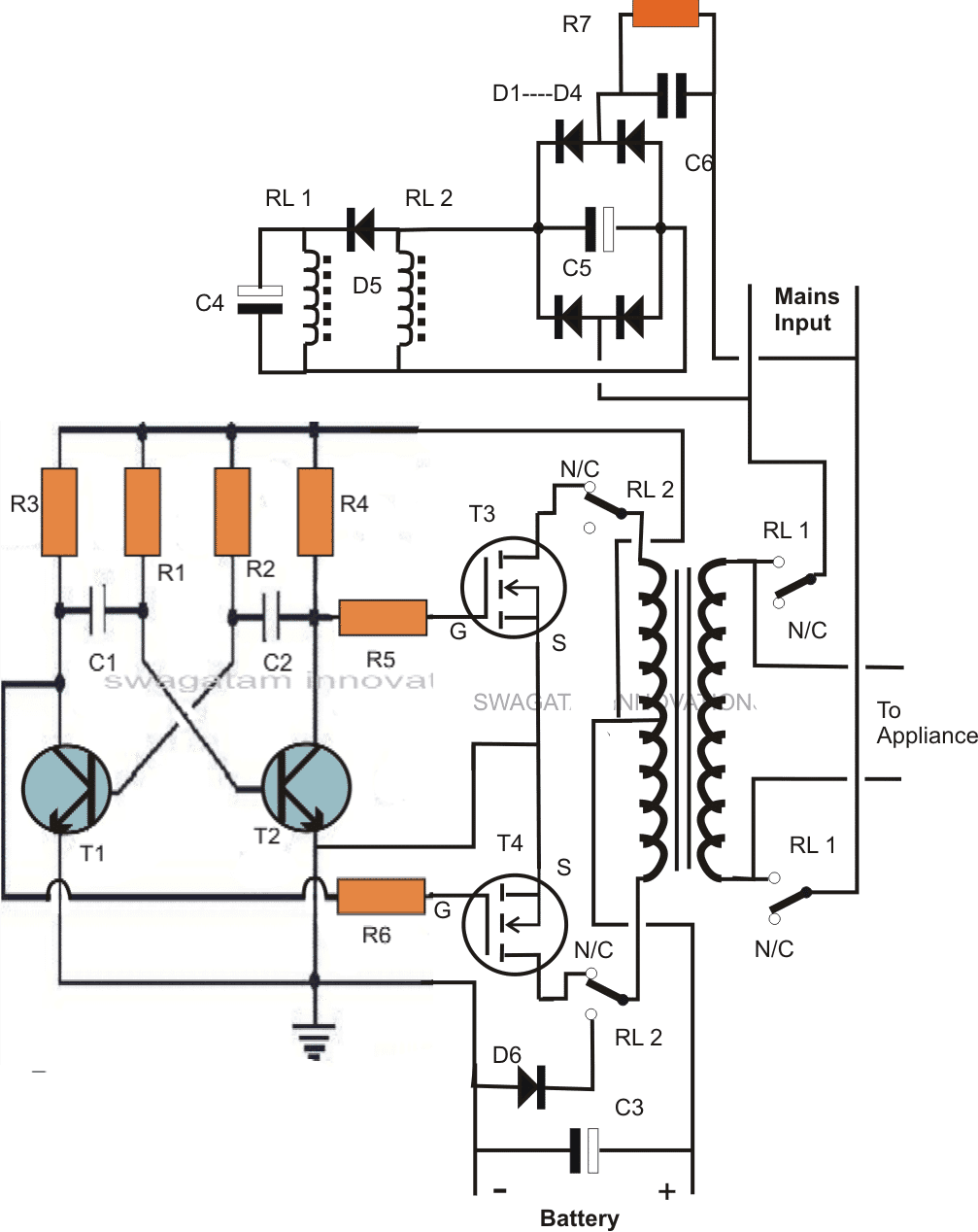
The circuit diagram below shows a design where a single power transformer is used for inverting purpose as well as for charging the battery when mains is present.
The good thing about the circuit is that the transformer doesn't employ separate winding for this, rather works with the same input winding and reverts DC to the battery with the help of a few DPDT relays.
The circuit can be understood with the following points:
How the Circuit Functions
The inverter section can be easiy recognized in the diagram, R1 to R6, including the T1 and T2 forms a general astable multivibrator circuit for producing the required 50 or 60 Hz pulses.
These pulses drive the mosfets alternately which in turn saturate the transformer by switching the battery voltage in it.
The secondary of the transformer generates the corresponding magnitude of AC which is finally used for operating the connected appliances.
The above configuration suggests an normal or ordinary inverter operation.
By adding a couple of DPDT relays in the above discussed operation, we can force the circuit to charge the battery in the prsence of an AC mains source.
The coils of the two relays are powered through a capacitive low current compact power supply, involving C6, C5, D1----D5.
The above circuit is connected to a mains AC source, this source is also connected to RL1 poles.
The second relay RL2 is wired up with input winding of the transformer.
In the absence of mains AC, the position of the relay contacts are in the N/C as shown in the figure.
In this position the mosfets get linked with the transformer input winding, and the battery with the circuit so that the inverter starts oscillating and the output appliances gets the AC power from the battery.
In the presence of mains AC the relay coils instantly get the required DC power and the contacts activate.
RL1 activates and connects the mains input to the transformer, the appliances also get connected with the mains AC in the process.
Also due to the action of RL2 the mosfets get disconnected from the transformer, while the the lower tap connects with D6.
Since the center is already connected to battery positive, the inclusion of D6 provides a half wave rectified voltage to the battery, which is effectively filtered by C3 so that the battery is able to get the required sufficient charging voltage.
The above charging process continues until mains is present, so it should be monitored manually. When mains fails, the action reverts into inverting mode without interrupting the appliance operations and by using a single transformer for both the operations.
C4 makes sure that RL1 always activates a shade later than RL2 for safety reasons.
CAUTION: THIS CIRCUIT IS DEFINITELY NOT RECOMMENDED FOR THE NEW HOBBYISTS, IT'S SUITABLE ONLY FOR THE EXPERTS. IF YOU ARE A NOVICE AND INTERESTED TO TRY THIS.... BUILD IT AT YOUR OWN RISK.
Parts List
- R1, R2 = 27K,
- R3, R4, R5, R6 = 470 Ohms,
- C1,C2 = 0.47uF/100V metallized
- T1, T2 = BC547,
- T3, T4 = any 30V, 10amp mosfet, N-channel.
- C3 = 47000uF/25V
- C4 = 220uF/25v
- C5 = 47uF/100v
- C6 = 105/400V
- R7 = 1M
- D1---D5 = 1N4007
- D6 = 1N5402
- RL1, RL2 = DPDT, 400 OHMS, 12V, 7 AMPS/220V
- Transformer = 12-0-12V, current as per requirement.
For only inverter design please refer to this ARTICLE
Using a 2-Wire Transformer
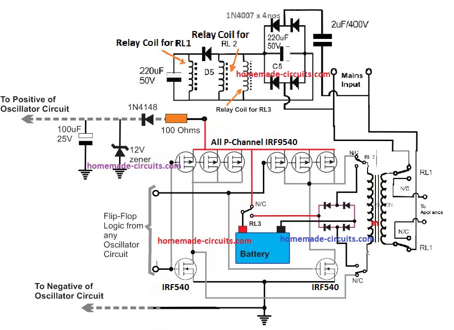
If you do not want to use a center tap transformer for the inverter, then you can use the following P-channel and N-channel MOSFET H-bridge inverter module for getting an identical single transformer inverter/charger results:


Questions & Answers
Acquiring 24V from 12V is difficult and is not recommended, because the transformer can become hot.
Wattage rating can be controlled by controlling the battery current through some circuit stage.
DEar sir,
Can i use a 10 A relay instead of the 7 A one used here
What precaution should be taken in order to safeguard the entire circuit before applying the ac mains to transformer's primary ?
And one more doubt sir
What does the connection (which seems like inductor coil )in the upper circuit means ? I realize that these are the connections across two relay pins and the upper circuit is the power feeding circuit for the relays. But i can't understand the 2 pins that i specified here. Please help me sir. I am not at all familiar with relays. Hoping your reply very soon sir……
Dear Arun,
Use a 100 watt bulb in series with one of the input mains wires for safety.
The inductors are the relay coils, a relay cannot be activated unless its coils are energized therefore these coils are supplied through the capacitive power supply shown at the upper section of the diagram.
….you may refer to this post for knowing more about relays:
https://www.homemade-circuits.com/2012/01/how-to-understand-and-use-relay-in.html
Sorry for disturbing you again sir. But what to do…. I have to be completely free of doubts before going for the design….. This time i am also coming with another doubt which may feel silly to you, please dn' t neglect it since i am not having deep knowledge in Electronics, but i like it.
I have a 300 W 12 V transformer having 4 thick windings at primary and 5 at secondary. I know it is a multi-tap one. But don't know how to wire them to suit for the single transformer inverter design.. Please help me……
How can i link the images with the comments in this blog ?
You can connect the 220V wires to mains and measure the tap voltages with a multimeter, in this way you would be able to figure out the tap values.
you can upload the images on any free image hosting site and provide me the link.
Sir that was not enough….. I need a better suggestion…….
My transformer is a locally made one. No markings ( even no separate colors for wires ) are there. The only thing that i could see that some set of the terminal wires are thicker than other set. From basic calculations of transformer design, i think the wires to bear large current are of secondary ( 300 W/ 12V ) and they have to be thick enough than the primary. Am i right ? If not please correct me…..
I am in a little bit confusion that how to connect the neutral and earth lines of ac mains into the transformer if it has 5 primary terminals as i calculated….. Please help me sir… Can you please suggest the exact connection schematics…..
Since it is an ac transformer, i willn't be able to measure the tap voltages exactly without a brige type rectifiers. Taking each tap voltage by changing the polarities supplied to the rectifier will be very time consuming..
I couldn't upload the images of the transformer…. SO PLZ HELP ME
you won't need a bridge rectifier at each tap for checking, you can do it with your meter on AC 220V range.
you can also check the taps by measuring their resistances…the one which gives the highest resistance can be assumed to be the mains input winding, connect a 100 watt bulb in series which testing with mains for avoiding possible hazards.
Very nice circuit sir.
Can i use a 300 W transformer in this circuit ? How much high will be the currents in both terminals ? Can i use the formula P= IV for its calculation. If i am doing so i will get maximum current
In primary : 1.304 A and
In secondary : 25 A…….. Is that will happen ?
If so, that diode (IN5402) used in Charging section sufficient to overcome this high amperage ?
What about the diodes at the primary if i am using the inverter to be run on a 300 W load. Reply me soon plz……. Sorry for the bad english…
Thanks Ramsree,
You can use P = IV, 25amps is right but that might be too high for the battery, because as per rules the ideal charging current should be 1/10th of batery AH, so we may have to upgrade the circuit with an additional current limiter circuit and also some modification in the relay wiring…..
Hey Dear, Did you add current limitation adjustments to the above circuit ever. Let me know. I think the design is wonderful. So we should work on it. Kindly share the link if you already posted about adding a limiter to this circuit.
current limitation for battery charging??
it could be done through a series LM338 IC configured in the current limiting mode
What modification you mean sir ? How can i modify this circuit to charge a 60 Ah battery bank effectively ? Can i use your one of previous post on ' 3 stage smart battery charger for 12 V ' with this.circuit ? What modifications to be done sir ?
a simpler approach would be to add a calculated current limiting resistor in series with D6
Hey check out this. I added regulation to your circuit:
imgur.com/gallery/A7gED
thanks, that's great!!
Dear sir,
Can you please give a model current limiting circuit to fullfill my need ? Can i have it to be used prior to the rectification section ? Thereby i can avoid using high ampere diodes there. that is why
Another doubt too sir,
If i am using battery rated below 100 Ah along with the current limiting circuit , will it be possible for the inverter to run maximum load that i am expecting with ?
As mentioned in the previous comment, the series resistor with D6 will not interfere with inverter power outputs, it will work with the specified full capacity
Thank you so much for this post. I will like to give you feed back after I complete the work and I will also prefer to know about circuit diagram.
Kindly, let me ask this question.
1. Is it possible to use this circuit with 24volts battery without any damage to the cell of the circuit?
Yes, 24V can be used, provided the transformer and the relays are also rated at 24V.
Hi Swag,
is it possible to use transformer with 6v – 0 – 6v and if yes what will be the output of it?
Thanks.
Hi Adeleke,
it would work with a 6V battery…output would be equal to the output rating of the transformer, if it's 220v then it would generate 220V
Hai sir,
Can i ask you something……
What modification to be done to the present circuit if i am using high current transformer ??
A series current limiting resistor alone will not do this purpose i think. What extra things to be added to the oscillation section to prevent ir from accidental damage due to high current flow. Also i want to know the necessary changes to be made on relay wiring also. Please try to REPLY MY ALL QUESTIONS SIR
Hi Venkitesh,
I'll try to find some appropriate solution and update it soon.
Hai sir it is again prithviraj speaking…..
A serious doubt is now disturbing me….
As per your suggestion, the inverter o/p after successful testing can be connected directly to the ac wall outlet. But in this inverter schematics, the relay coils are actuated by the ac mains. So if i am gonna follow my strategy, will the relay actuate on getting supply during inverter operation and continously turn ON and OFF ?????
Hi Prithviraj,
You are right, the above inverer cannot be inserted in the wall socket, because the relays would start vibrating ON/OFF due to the particular configuration employed in the circuit.
Thank you Sir for replying me fast. Now i want to know whether any modification can be done to the present structure to suit my need or can you suggest any other design for me. I know i am disturbing you a lot. But what to do, i willn't get a better sleep if the problem is kept unsolved….
I am not at all interested in connecting appliances directly to inverter terminal out, because it will cause discomfort in turning a particular device on at a room
I am sorry Prithviraj, there's no possible way out with the above circuit We can consider a manual option using DPDT switch for the changeovers.
Sir i think it is possible to solve the issue by any of these,,,,,,,,
What about using a descriminator circuit to distinguish the sinewave from the square wave( which is produced by the inverter ) and actuating the relay only on sine wave, i.e, during mains is present.
Another way i think, is to slightly make a change to the existing frequency of square wave ( which is 50 Hz ) and thereby identifying the power on condition by counting frequency of the incoming signal to the relay coil fed.
But i don't know how this will take effect or will be effective and also don't know how to arrange these modifications. ….. So can you please help me
I don't think that would help, in that case when the mains comes back it will first clash with the inverter AC and cause undesirable things to happen, a fire, a blown fuse etc. because once the the inverter AC gets into the wall socket it's bound to mix with the mains AC unless a DPDT is employed for isolating the respective ACs manually
Hellow sir, how did you calculate the value of resistors and capacitors incorporating the AMV stage of two.coupled transistors. I have to place available and suitable components there
Hello Rishikesh,
you can use the following formula
f = 1/1.4CR. where C = C1 = C2, and R = R1 = R2
R will be be in OHMs and C in FARADS
If the relay fails, won't it be dangerous to the inverter?
yes it could be dangerous, we can include a safety fuse for that in the circuit
hello Swagatam,
I interested in this circuit diagram but being novice, I'm finding difficult to understand the connect basically the operation of dpdt relay.
how many relays are required in this circuit diagram and how do I connect it pls
Thanks
Hello Agbadu,
If you are new in the field please do not try this circuit, it's strictly for the experts.
2nos DPDT relays are used in this circuit.
but pls sir can you explain the charging section relay connection for me
also can this circuit be converted to 2.5kva, if yes how?
Thanks
I have already explained it in the article, if you have a specific doubt you can ask it.
if the above basic model is confirmed then it can be modified for 2kva also.
Sir, tanks for the post
Pls I don't get how to connect RL2 to the two mosfet since one Relay is specified for the two I can only connection one successfully. Pls help explain
RL2 could be a DPDT type relay having two sets of contacts but a single coil controlling both the contacts simultaneously
Thanks, try to DPDT type Relay
Hi sir, I'm unable to lay me hand on DPDT type relay, can I use 4 SPDT relay instead of DPDT relay, pls quick reply will be appreciated, thanks
Hi kolley, yes that will also do.
Thanks
Hi Swagatam, thanks for the he'll so far. Pls which capacitor can I use instead of C1,C2,C3 and C6 am unable to get those capacitors here. Thanks
Hi Kolley,
the capacitor values cannot be changed, so you'll have to use as suggested.
the ones which are polarized need to be electrolytic while the others metallized polyester type.
please note that this project is not for the newbies and requires expert knowledge in the field…the circuit has the potentials of causing fire hazard and explosion if not done correctly.
Hello sir, I just finished testing the circuit,am having two problem,1.the mosfet get hot immediately I connect to d battery power and the wire that come from transformer spark to the extent of getting burnt when I connect it to + side of d battery.2 the is turns on and off repeatedly when I connect it to AC supply pls what can I do to rectify these problems.thanks. Pls a quick reply will be appreciated
Kolley, you have surely done something terribly wrong with the connections which I cannot diagnose from here.
remove the relays and make the inverter separately first, as given in this article:
https://www.homemade-circuits.com/2012/09/mini-50-watt-mosfet-inverter-circuit.html
use a separate transformer for charging the battery, the above circuit is not suitable for newcomers.
Dear Swagatam ,
I had a home inverter which i was using for charging my car battery. One day by mistake i left battery charging wires on floor ,after that i see no voltage in battery charging wires. I checked the main Ac fuse of inverter ,it is ok but one warning sticker is there on inverter that avoid shorting of charging wires other wise its DC fuse will blow . Kindly give some information on indian make inverters DC fuse location . Inverter make is Reliable . It has only one PCB on charging side supply is going to charging wires through heat sink having 4 MODFET each side.
Dear Hamza,
I am sorry, it'll be difficult to provide a proper suggestion regarding this since the configuration may be different for different inverters and I haven't yet opened the brand that you have mentioned.
However a fuse in any inverter will be always in series with the battery line and also could be with the output AC line, you can investigate these two positions, I am sure you would easily locate a few across these lines.
the relays are 12V , in Fig. it is directly connected to mains, pls explain
the right hand side contacts are connected with mains, the coils are connected via C6
Hi,
This question is not related to the post. Pls reply, I recently purchased a 12-0-12 transformer, and as I measured the V between both ends,it shows 0 V ( not 24V) and centre tap to each end it shows 12 V each. So what type winding is used in it?
may be the center taps are split, join the two center taps together you will then see 24V across the outer taps
Hi
No, the center tap is OK, because there is a continuity between both ends.
Hi, that's impossible, if the individual winding are showing 12V (from center to out), the outer taps will show the sum of the two winding.
something may not be correct with your meter or measuring procedure.
make sure the meter is selected in the AC range.
you may also check the continuity of the winding using the diode range in the meter.
….another issue could be the internal winding polarity of the trafo, which could be incorrectly wound.
I have a China inverter and a12v battery charger plz give me some circuit or understood me that if light is gone then automatically my battery give me back up and if light comes again then start battery charge automatically
I hope u understand my question
you can try the following circuit for implementing the required automatic changeovers:
https://www.homemade-circuits.com/2014/06/how-to-convert-inverter-to-ups.html
Sir, thanks a lot for your work here..
There's just one thing I'm a bit confused about in this circuit..
220VAC enters the bridge Rectifier from the mains input,, 220VDC comes out…. But the relays are rated for 12VDC
I'd like to know which of the components in the circuit does the job of limiting the 220VDC to the 12VDC required by the relay coils…. Thanks
Banimz, the capacitor output has very low current content therefore the 300V DC will automatically drop and adjust to the relay coil voltage.
no external limiting agent is required for this
Pls, how many mosfet of irfp 250 did I need to combine on my inverter to give 1000wat
Regards
Pls specify the voltage/amp specs of the mosfet, it will help me to calculate the parameters.
Thanks a lot….
Speaking of that capacitor…. I can't find a ceramic capacitor of 1uf anywhere near… But I do have an electrolytic capacitor of 2.2uf….
Will this affect the circuit???
I'm talking about C6…
C6 is a 105/400V PPC capacitor, it's abundantly and easily available in the market.
Is the capacitor C6 a very crucial part of the circuit? Or can I leave it out?
without C6 the relays will not operate.
Thanks so much for the quick respond
The mosfet voltage is vdss 200v and 33A
Regards
3 mosets on each channel would do.
but first you should try with single fets and try to accomplish a minimum 300 watt output
Okay, thanks…. So now I've gotten a 105/400V capacitor for C6….. And I've finished constructing the circuit…
Now I noticed something. If I connect power to the circuit before connecting a relay ,,,, the relay will trigger…
But if I connect the relay before turning on the power,,, the relay won't respond….. Upon testing, I discovered that just about 5V gets to the relay if it is connected before the power turns on…. Almost as if its acting as overload on the circuit……
What could be the cause of this and how can I rectify the problem??
Oh, also, both relays don't trigger at the same time,, whether power is connected beforehand or not….. Only one works at a time,,,, if I connect one and it triggers,, the other won't trigger……
Eagerly awaiting your response…
Thanks a lot for everything
The relays that you have are not of good quality, they might be having a very low resistance coil, in that case you should think of using a 12V AC/DC adapter instead of the C6 power supply.
The connections will be identical, the 12V from the adapter will connect with the relay coils including D5, C4….
D1—D4 and C2 may be removed.
The input of the adapter will need to be connected across the points indicated "mains input"
Sir, the circuit is now working well…. Except for one minor issue…. My relay coils are 90 ohms instead of 400…… Thus, the current this circuit is producing is too low to power both of them together….. …..
How can I increase the current in this circuit?? Should I reduce the 1M resistor??? Or something else? Eagerly awaiting your response.. Thanks a lot
You can use an adapter as stated in the previous comment…
Thanks so much
Pls can u tell me hw u calculate it, I mean the formula you used to cal the wattage of the mosfets.
Thanks
multiply its voltage rating and amp rating and reduce it to 25% for safety.
Thanks so much sir…
I was eventually able to get the required current and voltage to drive my relays by using four of the C6 capacitors in parallel…..
Its all working now.. Thanks a lot sir
It's my pleasure Banimz.
Sir thanks so much for your help so far,
Please help me, I build an inverter using IC SG3524 the inverter is working fine on some appliances but won't work on some like small or big fan, small hair clipper and a desktop computer, pls what can I do to make it work on all appliances?
Regards
I think I have already answered this in your previous comment…..
Sir pls answer me here,I can't find the link to the previous comment again on my computer
Or if u can provide the link for me I will be happy
Thanks
Hi Kolley,
It could be due to insufficient battery power or trafo wattage….measure the output voltage of the inverter when you connect those loads, if you find the voltage dropping would confirm an inadequate battery current or transformer wattage.
Thanks for the quick responds
The output voltage before those load is close to 240 but after connecting the load it drop to 220, which I think should be sufficient but still it won't power fan and clipper
220V is more than sufficient, that's weird, can't diagnose without seeing it practically…just check if both the power transistors are conducting uniformly, you can do it by connecting car headlight lamps in series with the transformer taps which are linked with the power devices….
Thank you sir
I will try that.
hi Sir Swagatam
i dont know much more about electronics basics, But i want to make this ups for my DSL Router and Laptop Charger , I understand the circuit, but DPDT Relay is confusing me ,
I have found that DPDT Relay have 6 points , 2 for coil, 2 for NC and 2 for Com,
Can you Please mention that how to use relay in this circuit and what is treatment for coil points,
If you Please explain the working of R1 and R2 while marking on a picture of DPDT so that i may knwo which points of relay i have to use and which of them are to be leave as it is ,
Please help me ,
Thanks
Hi Waqar,
I don't think you would require such a complex inverter circuit for a modem, charger application, you can try the following design:
https://www.homemade-circuits.com/2013/03/simple-dc-ups-circuit-for-modemrouter.html
C3 is 4700uf or 47000uf?
yes, C3 should be 4700uF……. and not 47000uF
hello…Mr.Swagatam
I want to make 1200w inverter but problem is in charging circuit I can't use relay for it because it take 100a in inverter mode and 10 in charging mode
I use 4xIRFZ44N mosfet
can I use MOSFET reverse diode in charging mode ????
hello janak, if you are referring to the above circuit, it cannot be used without relays….it would work only with the relays connected in the indicated manner
sir,
could you help me for making a simple inverter for lighting a 18w CFL ?
i have a 12V 9ah battery and 12-0-12 3A transformer.
Hope you may help me
Arun
arun, you can try the following circuit:
https://www.homemade-circuits.com/2012/09/mini-50-watt-mosfet-inverter-circuit.html
Ya i found it..
can i use IRF540 or IRFZ44 for T3 and T4
of the circuit on the link???
yes you can…
What is the output power of this ckt?
How much watts can it handle?
it will depnd on th trafo, battery and mosfet ratings
Can it handle a table fan motor load of 25-30 watts , if I use 12v 7ah battery and 12-0-12 ,1 A transformer
you will need a 9-0-9/5amp transformer, and a 12V 7AH battery for operating your fan properly
Hello Mr. Swagatam,
Please can I use this circiut for 24volts and at the same time use it for TV and other equipment in the house.
Hello Mr. Adelke,
No 24V cannot be used for this design since it employs a 12-0-12V transformer.
Hi Mr. Swagatam, very grateful for your response.
Please, if I want to convert it to 24volts is it possible and if YES, what are things that I needed to change from the circuit.
Thanks.
Hi Mr. Adelke, for that you might need a 20-0-20 transformer and a 48V battery
Hello sir swagatam,av got a two wire transformer rated 24v/240v. It’s a huge transformer that can deliver a maximum of 6000w. Do you mind sending me a circuit of a pure sinewave Inverter using this two wire transformer that can run a refrigerator or a freezer and a tube light? Also help me answer the following questions
1. Can this type of a transformer work on a 24v?
2. How many irf1404 should I use to achieve the 6000W?
3.How can I make it a single transformer inverter charger being able to indicate
a) when battery full
b) when float charging
c) when battery low
d) when there’s rise in mosfet temperature
? Help me with a circuit diagram if you have any sir,I’ll really appreciate.
Hello Evans,
Please refer to the last concept presented in the following article:
https://www.homemade-circuits.com/7-simple-inverter-circuits/
you can add more mosfets in the same proportion to increase its power output.
For battery indications you may have to use an external op amp circuit
sir swagatam,thanks for the response. But I still need assistance. the circuit you refered me to uses both P and N channel mosfets,now my main issue is that I wanted to use all N channel mosfets. so the diagram you gave wont apply,what do you think will happen,do you have a circuit for that?
Or rather you can suggest to me a P channel mosfet i can use that has the same specs as irf 1404???
Again for the battery monitor everything sounds okay but the circuit doesnt offer float charging and temperature indicator which might also involve a FAN??
Finally sir u have not advised me if i can use the transformer for a 24v inverter with a 24v battery bearing in mind that the transformer output is 24v ac??
Thanks and I look forward to hear from you.
Evans, using N channel is very difficult to configure, you can search for “full bridge inverter” through the search box, and you will be able to find a few designs
For mosfet specs you will have to some research by comparing VDs and ID and RDson. p channel mosfets have more resistance than n channel since their RDson or the resistance is much higher than n channel. You must Add p channel mosfets in parallel until their RDson value becomes almost equal to the lower n channel mpsfets
float charge is nothing but very low current feed to the battery which you can do simply by connecting the supply permanently through a high value resistor depending on the battery Ah.
Battery temperature will rise only if you provide over-current to the battery, and want to charge the battery faster than normal, which is not recommended. Temperature will not rise if you use a current that’s 10% of the battery Ah value.
24V transformer will produce 24 V AC and 33 V after full wave rectification.
thanks sir swagatam,one final question is that for a h bridge system ,is 24v transformer suitable for sinewave 24v inverter?
For 24V battery, the trafo must e approximately 18v, or if the trafo is 24v, the battery must be approximately 36v
thanks sir swagatam,one final question is that for a h bridge system ,is 24v transformer suitable for sinewave 24v inverter?
If pwm control is not used then matching battery/trafo is OK, if pwm is used then trafo voltage must be lower than battery voltage
Thank you very much sir swagatam. Please sir advise me, which one is the best sine wave inverter?
1. Inverter with pwm or,
2. Inverter without?.
Also I have done a rewinding to my transformer and now it’s reading 16.5ac. is the voltage okay for an inverter with pwm?
Evans, 16.5V transformer cannot be used with a 12V battery, please read the following post for more info:
https://www.homemade-circuits.com/how-to-calculate-and-match-inverter/
PWM inverter is better than an ordinary square wave.
Hello sir swagatam,am seeking info from you if 16.5v can charge 2*12v batteries.
1. If yes then how long will it take to charge the 2 batteries?.
2. If know ,then how can I boost the voltage to be able to cherge the 24v batteries?.
You will need an auto cut off system then you can use 16V input for charging 12 V batteries
Sorry sir,I think I didn’t put everything right for your understanding. I was asking if a transformer with 16.5v can charge 24v battery which are 2*12v connected in series?. Also how long will this take to be fully charged?
Again sir,you haven’t advised me concerning pwm inverters and those without pwm.
Evans, 16.5 V after rectification will give 16.5 x 1.41 = 23 V which is not sufficient to charge a 24 V battery. It must be at least 28 v
PWM is better since it allows waveform control.
Also sir swagatam,if u have an auto cutoff circuit for 24v, please help me with one. Sir in my last question,I was seeking to know if a transformer with an output of 16.5v can be used for an inverter with pwm. Thanks in advance.
For auto cut off you can refer to the following concept:
Op amp Battery Charger Circuit with Auto Cut Off
you can use the transformer for pwm inverter with a 24 V battery
sorry, the battery would need to be 24V not 48V….and the 470 ohms will need to be changed to 1K, while the 27k resistor calculated appropriately
Thank you Mr. Swagatam, very grateful for impacting others with your idea and knowledge.
Thank you.
You are most welcome Adeleke
If battery 48v..transformer need ?
for the above design it should be 0-48V
Syed Asim Ali zaidi, please I would like to have that diagram for charging and cut off,thanks. email: evansmworeh@gmail.com.
Hai, great cct
Hi Swagatam? What controls the charging time so as not to overcharge the battery? Thanks.
Hi Joseph, over charge cut off is not included in this design but since the battery is charged only upto 70% it won't harm the battery
Ok thanks.
Hello brother, as i look the diagram i see that battery charging system is half wave rectification when relay switches by mains 220v doesn't this damage the battery? Your design is simple than mine i designed using microcontroller. But i am still looking for the best charging method with cutt off for a 200Ah battery. I am using irf3205 mosfets and a 600w transformer. Any suggestion ? I will appreciate! Thanks and your posts are always amazing and informative
Thank you Syed, Half wave charging will not affect or harm the battery in any manner, you can improve the DC by increasing the filter capacitor value to some higher value….for example a 10,000uF could be tried t enhance the DC quality for the battery.
Why there is no surge protection that is done because of the capacitor no polarized like 2.2uf 400V between the mains terminals LIVE and NEUTRAL
the load here are the relay coils which are strong enough to neutralize the initial switch ON surge…
Thanks Swagatam this means alot. One more question if you don't mind "Do you think that two IRF3205 will do the job for 500-600W transformer with 200Ah battery." I'll share my design with you soon.
You are welcome Syed, yes it will work, but the heatsink will need to be adequately dimesioned and if possible cooled with a fan…
Hey Swagatham there let me know your E-mail. So i can send you my design which has better charging and cuttoff option
Hi Syed, you can send it to admin @ http://www.homemade-circuits.com
Thanks i got it.
Good Evening Sir,
Sir, can I replace C5 (that is 47uF/100v) with anyone bellow the or little above the specified on?
And for C6 (that is 105/400V) with 104/630v or 104/250v.
Thanks you Sir.
Aminu, the value needs to be little bigger, 105 or 104 will not be suitable, you can try 10uF/250V
C6 cannot be less than 105, otherwise the relays will not operate, in fact you must use two 105 in parallel
Hy I m bravo pls I don't see dat 0.47uf 100v cap in my area pls can I use 0.33uf electrolytic or pls give me any close value I can use anD for that relay I whan to use small 12v 500ma trafo to power d coils and the C3 I get 4700uf by 16v will all this be ok pls help me out. Tnks
Hi, 0.47uF, and 27K together are supposed to determine the 50Hz freq, 0.33uF will reduce the frequency….in that case you might have to increase the 27K to 33K or 39K to correct the frequency to the 50Hz level
Tnks for the reply
another question sir, (1) pls what will be the value of r1 nd r2 if I use 0.22uf electrolytic cap for c1 nd c2 to get the 50Hz, (2)what value of zener diode can I use to protect my mosfet from damage. tnks
1) you can use the followin softare for calculating them
https://www.homemade-circuits.com/p/transistor-astable-multibivrator-amv.html
use 1/50 = 0.02 for the time period slots
2) you can use 12V zeners although it won't be required if the supply is 12V
I get 474j/250v for c1 nd c2, will it be ok for the same value of r1 nd r2 which is 27k
(2) What if I use 1n4007 to protect my mosfet?
Tnks
it will do.
mosfets already have built in freewheel diodes there's no need of an external diode.
anyway 1N4007 will not be enough….you can try 1N5408 instead for your satisfaction.
Hi Swagatam, thnx for the huge efforts, very helpful. I've a question plz, I am troubleshooting an inverter, it's not charging the battery anymore, the output goes to the battery is 7.5v, which should be no less than 12v. Plz what could be the reason for that?
Thanks in advance.
Thanks Taher, please disconnect everything that's connected with the transformer or the source of the supply, and check whether it reads around 14/15V or not, if yes then the problem could be somewhere in the adjoining electronics or controller which will need to identified appropriately….if the source shows less voltage then it will need to be replaced with a new one.
Hello sir please c1 c2 c5 can I use 100v 10uf because I can’t find the real values
I would recommend to do exactly as specified in the diagram, any other values can be dangerous….for C1/C2 the values can be slightly changed, for C5 also the uF value can be changed but it must be strictly 400V rated
Please sir can I use100v 10uf in the place of c1 c2 c5 because I can’t find the real values in my area
No!!
Hi sir, I have successfully completed the project, but I just wish I could increase the power of the inverter through mosfet, can I use six mosfet in parallel in this circuit instead of two?
That’s great Frank, yesy ou can use 6 or more mosfets in parallel for increasing the power handling capacity along with the trafo and battery which will need to be equally upgraded
Hie Sir
Is the polarity of C5 correct?
Hi Francis, sorry it’s a mistake, please connect the positive lead with positive of bridge….
I have just constructed a similar inverter /charger but for the oscillation I used SG3524 ic. When I powered the inverter it worked great and when I plugged the AC mains it stopped inverting and stated charging the battery. But when disconnected the mains, I heard a continuous clicking sound from the relays and powered off the inverter but mosfet were shorted. Replaced mosfets again did the same but am sure I labled my relays correctly and I just switched the relays and no problem now worked. JUST DON’T KNOW HOW?
It will need to be examined carefully by switching the operations repeatedly, it will be difficult to judge without a practical test
Is there any problem if i overlap the winding of the transformer because i am making the transformer my self
yes, the efficiency will be greatly affected.
Can i use 12-0-12 1 amp transformer and 4 ampere transistor for working 15 watts soldering iron
yes will do!!
The transistor heats up when i use ferrite transformer but when i use iron core it didn’t get heatup at all. The ferrite transformer i use is got from from a old 120w inverter i am only using your Oscillator section of your circuit
ferrite trafo will require a high frequency in the order of 20kHz, for iron core it is just 50Hz which is not compatible with ferrite core trafo
If i use 2n3055 transistor instead of mosfet do i need to change the resistor
you will need to add additional driver stage as this
https://www.homemade-circuits.com/50-watt-inverter-might-look-quite/
I have 600 va ups transformer but i dont know its secondary winding there are so many wire. How can i identify this??
Could you identify the primary winding which is supposed to be connected with the mains AC?
Sir i know the 12-0-12 winding detail what i need is the coils connected to ac mains
Elec, take another 12-0-12V known transformer, connect it to AC mains and feed its 12-0-12V AC to your UPS transformer’s 12-0-12V wires, now check randomly across the output wires to find which one gives the accurate 220V, or 230V
Thanks for helping now i got the right winding
If i want 500 watts from 12v 7ah battery how much amp transformer is needed
getting 500 watt from 12V/7AH is not possible…you will need a 200 AH battery for that
Hello Mr Swagatam. I very much appreciate your posts. Coming for years. I have to help with an inverter scheme for this pump. What scheme do you recommend? Thousands of thanks. Excuse me for my bad english. Please email me gogutu68 @ gmail.comfile:///home/probe/Desktop/pompa_es_2_dr_web.png
Thank you gelu, the shown link is not working in my PC. and also you will have to provide the technical specification of the motor in detail so that I can suggest you the right circuit
If you do not see the details, please tell me where to upload the pictures. Thanks again
the links which you are trying to send can be visualized only by you in your PC, it cannot be visualized by me or anybody else.
You can send the specifications in written, that will be enough, image is not required.
Technical data
maximum head MCA 5,7
maximum flow cm/h 2,7
power supply v/hz 230/50hz
fluid temperature grdC 2-95
ambient temperature grdC 0-40
storage temperature grdC -20-70
mahimum percentage % 40
ECM equipment regulations cf EN 610-3-2/EN 61000-3-3/EN55014-1/EN55014-2
Ferroli Energy Saving (ES) 25-60 /180 is an eficient electronic glandlles pump driven by a permanent magnet synchronous motor,fitted with frequency (inverter technology) The pump body is made of cast iron treated by cataphoresis to withstand the corosive action of the condensate.
TECHNICAL SPECIFICATION UM lt it 25-60 / 180
Gelu, I only need the voltage and wattage of the pump, and whether it is a DC or AC, please provide these info, the voltage seems to be 230V AC, so just provide the wattage…
Thank you sir for helping by posting circuits . How much is the current rating of the transformer if I want to charge 24v 18ah battery ?
Hi Nikhil, you can use a 24-0-24V/3 amp transformer, make sure the filter capacitor is rated at least 6800uF/50V
Ok thank you Sir . And Sir I am using eg8010 as inverter section , so how can I connect both battery and H bridge configuration in transformer .
sorry, it can be done only with the above shown configuration, other configurations may not work as inverter/charger using a single transformer.
Sir swagatam,do you mean h bridge inverters don’t use single transformer for inverter and charger? Many inverter chargers I have repaired only uses one transformer,and most of them you will see the transformer primary connected directly to the drains without the relays but they do charging,pliz enlighten me what happens and infact the mosfets uses for inverter are the same that do the charging. Help me understand more so with a non centre tap transformer.
Evans, Actually it can be done by isolating the transformer from the H-bridge through a relay, such that the relay disconnects the transformer from the H-bridge and the connects the transformer with a bridge rectifier and filter for charging the battery….it may be actually easier than a center tap transformer.
Hi swagatam thanks for your reply, please help me know this
1. Inverters with a non centre tap transformer and those with centre tap which one is more efficient in terms of service delivery and output wattage?
Evans, 2 wire topology is more efficient in terms of cost, size, wattage.
Also sir as you have indicated in your reply above concerning the use of a relay in isolation of transformer from h-bridge to bridge rectifier,help me know how to select the size of a relay that would be capable of handling the primary current of a 5000W inverter transformer to be able to charge 2×200AH batteries.
The relay contacts must be 2 times more than the specified charging current, for 400 Ah this could be a 80 amp relay
Also the relay should be able to handle current during Inverter and charging, urgently waiting to hear from YOU.
hi Sir, I need pure sine wave inverter without microprocessor
Hi Sunshine, I have explained many of them in this website, you can find them here:
https://www.homemade-circuits.com/category/dc-to-ac-power-converters/
Dear Sir,
If seen carefully in the circuit, when on an idle state the relays are not activated and the mosfet drains have access to the trafo taps via relay 2……this will make the inverter function normally when battery is connected.
But the oscillator circuit is being continuously powered when the mains is active…….this has been un-noticed when you designed this circuit…..I found this through mental simulation.
The oscillator gets a half wave unregulated power from the transformer and remains continuously on while the battery is charging……how to avoid this?
I have bought all components and ready to make the circuit….please help here.
Dear Sherwin,
There’s no easy way to eliminate that, and anyway it does not matter because the oscillator wouldn’t draw more than some milliamps.
Thank you for circuit more grace.actually what if the relays fails won’t the be any disavantage on the mosfet.wont dey butn plz reply
If the relays fail, the circuit will burn, you can add a fuse to prevent that….
Good day sir, an inverter I use well at home and charges well, when I give it to someone , it never charge a single volt with generator in that house because they don’t have power in the house. They use the generator to pump their 1.5hp pump. The inverter is serving during automatic changeover but not charging the battery at all. Please what could be wrong sir.
Adeyemi, please check the DC voltage from the generator which is used for charging the battery, that will clarify the situation.
Thanks for always being there, Swagatam. How can I appropriately rate the breaker in auto changeover inverter charging system against sulfation tripping off.
Sorry Adeyemi, I do not have any idea about it.
EngineerSwagatam.
Good evening.
I am pleased to have found this page interesting and useful, as it teaches about power electronics. I am a hobbyist who recently dabbled in this investor issue. I have assembled this circuit in Proteus to be able to simulate it. But of course, the simulation is not given in the first instance since you have to understand the design. My big question: can this circuit work with the load and at the same time it can feed back the battery, in order to be able to work continuously 24 hours x 7 days? My thanks in advance for the attention given to this.
Atte.José Javier González.
Thank you Jose, I am glad you found this site useful!
Yes simulation might not sometimes give us the desired results, and we have to ultimately build and test a given project practically.
No, sorry, it is not possible to discharge a battery via an inverter and simultaneously charge the battery from its output, because the inverter will work with 10 to 20% losses which will never allow this process to succeed.
Swagatam Engineer.
Good evening. Thank you very much for your precious reply. I am studying all this topic regarding CA – CD Invertor based on your valued page www. His answer reveals the principle of energy: it is neither created nor destroyed. So based on this principle, do you mean I should design the circuit adding a second battery of equal voltage and amperage that feeds back the first battery? Or will the initial battery increase its capacity for the same inverter in question? My thanks in advance for the attention given to this.
Atte. José Javier González.
You are welcome Jose, no, even using two batteries will not help to produce power 24/7, eventually both the batteries will get exhausted.
Thank you for your response. Please, how many pin does RL1 and RL2 has. Or probably not all the pins are used in RL2. Kindly help with this.
8 pin each, please Google DPDT relay you will easily get all the details.
Thank you for your apt response always.
Kindly help me with these analysis on the battery charger diagram if I am correct.
Relay 1 and 2 coils are connected before and after D5
The common pins are connected to the transformer
NO is connected to the appliance
NC is connected to mains input.
Please I want to know if I am correct with this analysis.
Thanks
That’s right, N/O of RL1 are also connected to the transformer 220V wires.
Thank you for your swift response.
I need your advice.
1) I want to use a 12-0-12v transformer with a 24v battery, what is your advice sir.
2) A 10amp 28VDC relay for this circuit been a battery charger inverter.
You are welcome Emmanuel!
1) It will work if your inverter frequency is PWM based and with 50% duty cycle
2) for 24v battery, the relay must be 24v also
Thanks sir.
In one of your article there is a diagram for 500w inverter. That is the diagram I am following. But in my case, my target watt is maximum of 150 to 200w. In other to achieve that, I didn’t use a transistor with the two MOSFET but I want to use every other components you have on the diagram.
So according to the diagram of 500w inverter.
1) Is it a PWM inverter or not.
I want to be clear on that sir.
2) And if it is not, how do I make it a PWM inverter with 50% duty circle as you have said sir.
Emmanuel, you can try the first or the second circuit from the following article, which are compatible with your transformer specifications.
The IC must be supplied 12V from a 7812 or any step down converter
https://www.homemade-circuits.com/modified-sine-wave-inverter-circuit-2/
does anyone has the PCB diagram to print a PCB form.
Helpful
Pls 24v ups my ups did not bring 230v output, it bring 170v why any help
Is your battery fully charged? And is the 170V with load or without load?
180v with load and battery is fully charge
Try reducing the load, and check the voltage. If the voltage rises with lower loads then the problem could be due to low power transformer and battery which are unable to handle the load that you are applying.
In a H-bridge design, transformers input volt are usually half of the battery volt. For example, a 12vDC to 220vAC inverter transformer is usually 6v-220v, while a 24vDC to 220vAC inverter transformer is usually 14v-220v. Now my question is this, with the above circuit, when AC mains is present, the transformer will return it’s winding voltage back to the battery I.e if it’s a 12v system, then 6v Wil be sent to the battery, or if it’s a 24v system, then 14v will be sent to the battery which will not be sufficient to charge the battery. So, how to solve this problem?
In an H-bridge circuit the mosfets will supply the full battery voltage to the load, if a 12V DC is connected to the H bridge mosfet drain, then this 12V will be alternately switched to the connected transformer primary.
If this is the case, then why use transformer with primary winding is half of the voltage of the battery in any H-bridge configuration? All inverters i have seen and repaired which are H-bridge configuration, uses transformer half the battery voltage. I opened a 48v -220v inverter yesterday, and the transformer is 26v primary and 220v secondary.
And if a mosfet of H-bridge gives full battery voltage i.e. 12v into 6v winding, then the output of the inverter should also double, like 440v thereabout.
Transformer winding will be half only when the H-bridge is a PWM based inverter, in which the load gets only the average 50% of the total Dc supply due to the PWM. If it is not a PWM then the load will get the full DC supply.
Thank you for the response. Now, in a PWM h-bridge, will this charging circuit be applicable?
The H bridge charger circuit shown above has nothing to do with H-bridge mosfets or PWM. In the presence of grid AC mains voltage, the transformer is directly connected with the battery through a bridge a rectifier and relays for the required charging of the battery.
I understand the circuit perfectly. My concern is the transformer. If AC mains is present at the 220v side of the transformer, then the other side of the transformer will have 6v because that is the default winding. Which is why I’m wondering if the 6v will work for charging a 12v battery.
Normally if the transformer is 12v-220v winding, then definitely there won’t be a problem. But since the transformer is not winded like that, what’s going to happen?
Yes, in that case a PWM based H-bridge cannot be used in this charger concept.
Thank you so much for the clarification sir. God bless you
You are most welcome!
Mr Swagatam, I have a difficult situation with your design here, please i really need your help.
I just designed a 2.5kva inverter using your recommended single centre-tap transformer method. I really appreciated the design on light loads, however, when I asked my client to turn on his fridge, the system shut down, then I found out that the 20am relays at the mosfet input to the transformer got burnt due to high current passage. Now, this is a very difficult situation for me now as removing the relays has cost me a lot of mosfets as the mosfets now have direct contact with the transformer primaries, especially whenever I try to input mains to charge the batteries. I don’t know what to do, please help me. Is there no other design that can work with a single relay?. Thanks
Hello Ubochi,
I am glad you could build the circuit successfully, however, you should have selected the relays appropriately according to the load.
For a 12V 2.5 kva load the relay contacts must be rated at 2500 / 12 = 208 amperes….that looks huge right, but that is how the relays must be rated, at 210 amps each for the mosfet side relays. If you replace the relays correctly with 210 amp relays then I think the inverter should start responding correctly. However for 210 amp relays the C6 capacitor will need to be increased to 5uF/400V
I really appreciate your kind response sir, thank you so much. But I’ve studied most high power inverters, however they’re without this high relay capacity you just recommended for me, their transformer primaries are screwed directly on the collector rails of the mosfets. Just with a single relay, I did not understand the magic they used in controlling the both the charging as well as inverting systems.
Ubochi, If you are using 2kva load at the output, then the transformer primary has to switch a 2kva current through the mosfets and the relay contacts, isn’t it? So isn’t the mosfet and the relay must be rated to handle that much current and load?? Moreover if your relay contacts are burning that clearly shows that the relay contacts are experiencing heavy load which is beyond their handling capacity.
Sorry for asking much sir, but the final one now. Since a relay of about 200amps capacity would be big and probably expensive and might also not fit into the space provided, can a MOSFET of about 200ampsof current capacity be applied in place of the relay since it is going to be switching between the battery and the center-tap part of the transformer?. Thanks in anticipation
Sorry, no that might not be feasible, because an inverter/charger changeover circuit can be built only using relays and not using mosfets.
How do I charge a 120v DC battery bank with this circuit, what do I change?
If your inverter mosfets and transformer are rated to work with 120V, then the above basic setup will be the same, however the relay coils will also need to be rated at 120V
Hello Sir. I need a circuit diagram on inverter with automatic changeover system
Hi Jedidiah, you can try implementing the following concept with any inverter for getting the intended results.
https://www.homemade-circuits.com/how-to-convert-inverter-to-ups/
Thank you
My inverter transformer using 2 IRF840 MOSFETs is just producing some sounds when an incandescent bulb is connected across the output. The bulb doesn’t light. Also, when there is no load at the output the transformer sparks at the output windings. how should I go about it please?
It looks like your transformer winding has internal short circuit, so please replace it with a new one and check again.
Can the two relays and bridge rectifier at the primary terminals of the transformer be removed so that the mosfet diodes be used for the charging?
I don’t think replacing the relays with MOSFETTs is possible in the above concepts…