In this post I have explained how to build an innovative inverter circuit with a single transformer that works both as an inverter and a battery charger transformer, I have explained the details from the following discussion.
The Circuit Objective
Though you may find many inverters having an integral battery charger, the section will mostly employ a separate transformer for implementing it.
In the following post I have explained a unique design which utilizes the inverter transformer for power inverting as well as for charging the battery.
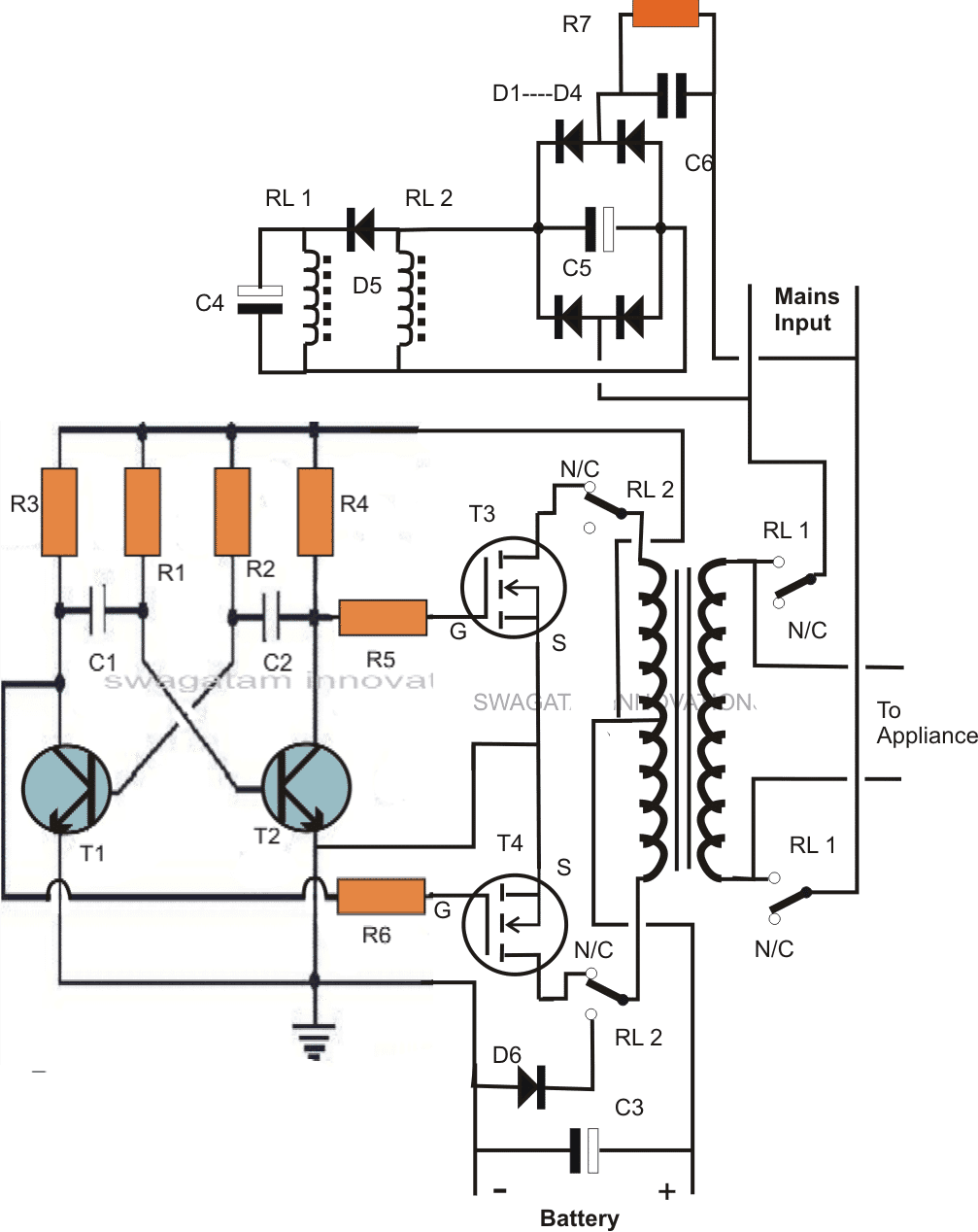
The circuit diagram below shows a design where a single power transformer is used for inverting purpose as well as for charging the battery when mains is present.
The good thing about the circuit is that the transformer doesn't employ separate winding for this, rather works with the same input winding and reverts DC to the battery with the help of a few DPDT relays.
The circuit can be understood with the following points:
How the Circuit Functions
The inverter section can be easiy recognized in the diagram, R1 to R6, including the T1 and T2 forms a general astable multivibrator circuit for producing the required 50 or 60 Hz pulses.
These pulses drive the mosfets alternately which in turn saturate the transformer by switching the battery voltage in it.
The secondary of the transformer generates the corresponding magnitude of AC which is finally used for operating the connected appliances.
The above configuration suggests an normal or ordinary inverter operation.
By adding a couple of DPDT relays in the above discussed operation, we can force the circuit to charge the battery in the prsence of an AC mains source.
The coils of the two relays are powered through a capacitive low current compact power supply, involving C6, C5, D1----D5.
The above circuit is connected to a mains AC source, this source is also connected to RL1 poles.
The second relay RL2 is wired up with input winding of the transformer.
In the absence of mains AC, the position of the relay contacts are in the N/C as shown in the figure.
In this position the mosfets get linked with the transformer input winding, and the battery with the circuit so that the inverter starts oscillating and the output appliances gets the AC power from the battery.
In the presence of mains AC the relay coils instantly get the required DC power and the contacts activate.
RL1 activates and connects the mains input to the transformer, the appliances also get connected with the mains AC in the process.
Also due to the action of RL2 the mosfets get disconnected from the transformer, while the the lower tap connects with D6.
Since the center is already connected to battery positive, the inclusion of D6 provides a half wave rectified voltage to the battery, which is effectively filtered by C3 so that the battery is able to get the required sufficient charging voltage.
The above charging process continues until mains is present, so it should be monitored manually. When mains fails, the action reverts into inverting mode without interrupting the appliance operations and by using a single transformer for both the operations.
C4 makes sure that RL1 always activates a shade later than RL2 for safety reasons.
CAUTION: THIS CIRCUIT IS DEFINITELY NOT RECOMMENDED FOR THE NEW HOBBYISTS, IT'S SUITABLE ONLY FOR THE EXPERTS. IF YOU ARE A NOVICE AND INTERESTED TO TRY THIS.... BUILD IT AT YOUR OWN RISK.
Parts List
- R1, R2 = 27K,
- R3, R4, R5, R6 = 470 Ohms,
- C1,C2 = 0.47uF/100V metallized
- T1, T2 = BC547,
- T3, T4 = any 30V, 10amp mosfet, N-channel.
- C3 = 47000uF/25V
- C4 = 220uF/25v
- C5 = 47uF/100v
- C6 = 105/400V
- R7 = 1M
- D1---D5 = 1N4007
- D6 = 1N5402
- RL1, RL2 = DPDT, 400 OHMS, 12V, 7 AMPS/220V
- Transformer = 12-0-12V, current as per requirement.
For only inverter design please refer to this ARTICLE
Using a 2-Wire Transformer
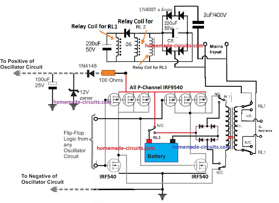
If you do not want to use a center tap transformer for the inverter, then you can use the following P-channel and N-channel MOSFET H-bridge inverter module for getting an identical single transformer inverter/charger results:




Questions & Answers
Acquiring 24V from 12V is difficult and is not recommended, because the transformer can become hot.
Wattage rating can be controlled by controlling the battery current through some circuit stage.
DEar sir,
Can i use a 10 A relay instead of the 7 A one used here
What precaution should be taken in order to safeguard the entire circuit before applying the ac mains to transformer's primary ?
And one more doubt sir
What does the connection (which seems like inductor coil )in the upper circuit means ? I realize that these are the connections across two relay pins and the upper circuit is the power feeding circuit for the relays. But i can't understand the 2 pins that i specified here. Please help me sir. I am not at all familiar with relays. Hoping your reply very soon sir……
Dear Arun,
Use a 100 watt bulb in series with one of the input mains wires for safety.
The inductors are the relay coils, a relay cannot be activated unless its coils are energized therefore these coils are supplied through the capacitive power supply shown at the upper section of the diagram.
….you may refer to this post for knowing more about relays:
https://www.homemade-circuits.com/2012/01/how-to-understand-and-use-relay-in.html
Sorry for disturbing you again sir. But what to do…. I have to be completely free of doubts before going for the design….. This time i am also coming with another doubt which may feel silly to you, please dn' t neglect it since i am not having deep knowledge in Electronics, but i like it.
I have a 300 W 12 V transformer having 4 thick windings at primary and 5 at secondary. I know it is a multi-tap one. But don't know how to wire them to suit for the single transformer inverter design.. Please help me……
How can i link the images with the comments in this blog ?
You can connect the 220V wires to mains and measure the tap voltages with a multimeter, in this way you would be able to figure out the tap values.
you can upload the images on any free image hosting site and provide me the link.
Sir that was not enough….. I need a better suggestion…….
My transformer is a locally made one. No markings ( even no separate colors for wires ) are there. The only thing that i could see that some set of the terminal wires are thicker than other set. From basic calculations of transformer design, i think the wires to bear large current are of secondary ( 300 W/ 12V ) and they have to be thick enough than the primary. Am i right ? If not please correct me…..
I am in a little bit confusion that how to connect the neutral and earth lines of ac mains into the transformer if it has 5 primary terminals as i calculated….. Please help me sir… Can you please suggest the exact connection schematics…..
Since it is an ac transformer, i willn't be able to measure the tap voltages exactly without a brige type rectifiers. Taking each tap voltage by changing the polarities supplied to the rectifier will be very time consuming..
I couldn't upload the images of the transformer…. SO PLZ HELP ME
you won't need a bridge rectifier at each tap for checking, you can do it with your meter on AC 220V range.
you can also check the taps by measuring their resistances…the one which gives the highest resistance can be assumed to be the mains input winding, connect a 100 watt bulb in series which testing with mains for avoiding possible hazards.
Very nice circuit sir.
Can i use a 300 W transformer in this circuit ? How much high will be the currents in both terminals ? Can i use the formula P= IV for its calculation. If i am doing so i will get maximum current
In primary : 1.304 A and
In secondary : 25 A…….. Is that will happen ?
If so, that diode (IN5402) used in Charging section sufficient to overcome this high amperage ?
What about the diodes at the primary if i am using the inverter to be run on a 300 W load. Reply me soon plz……. Sorry for the bad english…
Thanks Ramsree,
You can use P = IV, 25amps is right but that might be too high for the battery, because as per rules the ideal charging current should be 1/10th of batery AH, so we may have to upgrade the circuit with an additional current limiter circuit and also some modification in the relay wiring…..
What modification you mean sir ? How can i modify this circuit to charge a 60 Ah battery bank effectively ? Can i use your one of previous post on ' 3 stage smart battery charger for 12 V ' with this.circuit ? What modifications to be done sir ?
a simpler approach would be to add a calculated current limiting resistor in series with D6
Dear sir,
Can you please give a model current limiting circuit to fullfill my need ? Can i have it to be used prior to the rectification section ? Thereby i can avoid using high ampere diodes there. that is why
Another doubt too sir,
If i am using battery rated below 100 Ah along with the current limiting circuit , will it be possible for the inverter to run maximum load that i am expecting with ?
As mentioned in the previous comment, the series resistor with D6 will not interfere with inverter power outputs, it will work with the specified full capacity
Thank you so much for this post. I will like to give you feed back after I complete the work and I will also prefer to know about circuit diagram.
Kindly, let me ask this question.
1. Is it possible to use this circuit with 24volts battery without any damage to the cell of the circuit?
Yes, 24V can be used, provided the transformer and the relays are also rated at 24V.
Hi Swag,
is it possible to use transformer with 6v – 0 – 6v and if yes what will be the output of it?
Thanks.
Hi Adeleke,
it would work with a 6V battery…output would be equal to the output rating of the transformer, if it's 220v then it would generate 220V
Hai sir,
Can i ask you something……
What modification to be done to the present circuit if i am using high current transformer ??
A series current limiting resistor alone will not do this purpose i think. What extra things to be added to the oscillation section to prevent ir from accidental damage due to high current flow. Also i want to know the necessary changes to be made on relay wiring also. Please try to REPLY MY ALL QUESTIONS SIR
Hi Venkitesh,
I'll try to find some appropriate solution and update it soon.
Hai sir it is again prithviraj speaking…..
A serious doubt is now disturbing me….
As per your suggestion, the inverter o/p after successful testing can be connected directly to the ac wall outlet. But in this inverter schematics, the relay coils are actuated by the ac mains. So if i am gonna follow my strategy, will the relay actuate on getting supply during inverter operation and continously turn ON and OFF ?????
Hi Prithviraj,
You are right, the above inverer cannot be inserted in the wall socket, because the relays would start vibrating ON/OFF due to the particular configuration employed in the circuit.
Thank you Sir for replying me fast. Now i want to know whether any modification can be done to the present structure to suit my need or can you suggest any other design for me. I know i am disturbing you a lot. But what to do, i willn't get a better sleep if the problem is kept unsolved….
I am not at all interested in connecting appliances directly to inverter terminal out, because it will cause discomfort in turning a particular device on at a room
I am sorry Prithviraj, there's no possible way out with the above circuit We can consider a manual option using DPDT switch for the changeovers.
Sir i think it is possible to solve the issue by any of these,,,,,,,,
What about using a descriminator circuit to distinguish the sinewave from the square wave( which is produced by the inverter ) and actuating the relay only on sine wave, i.e, during mains is present.
Another way i think, is to slightly make a change to the existing frequency of square wave ( which is 50 Hz ) and thereby identifying the power on condition by counting frequency of the incoming signal to the relay coil fed.
But i don't know how this will take effect or will be effective and also don't know how to arrange these modifications. ….. So can you please help me
I don't think that would help, in that case when the mains comes back it will first clash with the inverter AC and cause undesirable things to happen, a fire, a blown fuse etc. because once the the inverter AC gets into the wall socket it's bound to mix with the mains AC unless a DPDT is employed for isolating the respective ACs manually
Hellow sir, how did you calculate the value of resistors and capacitors incorporating the AMV stage of two.coupled transistors. I have to place available and suitable components there
Hello Rishikesh,
you can use the following formula
f = 1/1.4CR. where C = C1 = C2, and R = R1 = R2
R will be be in OHMs and C in FARADS
If the relay fails, won't it be dangerous to the inverter?
yes it could be dangerous, we can include a safety fuse for that in the circuit
hello Swagatam,
I interested in this circuit diagram but being novice, I'm finding difficult to understand the connect basically the operation of dpdt relay.
how many relays are required in this circuit diagram and how do I connect it pls
Thanks
Hello Agbadu,
If you are new in the field please do not try this circuit, it's strictly for the experts.
2nos DPDT relays are used in this circuit.
but pls sir can you explain the charging section relay connection for me
also can this circuit be converted to 2.5kva, if yes how?
Thanks
I have already explained it in the article, if you have a specific doubt you can ask it.
if the above basic model is confirmed then it can be modified for 2kva also.
Sir, tanks for the post
Pls I don't get how to connect RL2 to the two mosfet since one Relay is specified for the two I can only connection one successfully. Pls help explain
RL2 could be a DPDT type relay having two sets of contacts but a single coil controlling both the contacts simultaneously
Thanks, try to DPDT type Relay
Hi sir, I'm unable to lay me hand on DPDT type relay, can I use 4 SPDT relay instead of DPDT relay, pls quick reply will be appreciated, thanks
Hi kolley, yes that will also do.
Thanks
Hi Swagatam, thanks for the he'll so far. Pls which capacitor can I use instead of C1,C2,C3 and C6 am unable to get those capacitors here. Thanks
Hi Kolley,
the capacitor values cannot be changed, so you'll have to use as suggested.
the ones which are polarized need to be electrolytic while the others metallized polyester type.
please note that this project is not for the newbies and requires expert knowledge in the field…the circuit has the potentials of causing fire hazard and explosion if not done correctly.
Hello sir, I just finished testing the circuit,am having two problem,1.the mosfet get hot immediately I connect to d battery power and the wire that come from transformer spark to the extent of getting burnt when I connect it to + side of d battery.2 the is turns on and off repeatedly when I connect it to AC supply pls what can I do to rectify these problems.thanks. Pls a quick reply will be appreciated
Kolley, you have surely done something terribly wrong with the connections which I cannot diagnose from here.
remove the relays and make the inverter separately first, as given in this article:
https://www.homemade-circuits.com/2012/09/mini-50-watt-mosfet-inverter-circuit.html
use a separate transformer for charging the battery, the above circuit is not suitable for newcomers.
Dear Swagatam ,
I had a home inverter which i was using for charging my car battery. One day by mistake i left battery charging wires on floor ,after that i see no voltage in battery charging wires. I checked the main Ac fuse of inverter ,it is ok but one warning sticker is there on inverter that avoid shorting of charging wires other wise its DC fuse will blow . Kindly give some information on indian make inverters DC fuse location . Inverter make is Reliable . It has only one PCB on charging side supply is going to charging wires through heat sink having 4 MODFET each side.
Dear Hamza,
I am sorry, it'll be difficult to provide a proper suggestion regarding this since the configuration may be different for different inverters and I haven't yet opened the brand that you have mentioned.
However a fuse in any inverter will be always in series with the battery line and also could be with the output AC line, you can investigate these two positions, I am sure you would easily locate a few across these lines.
the relays are 12V , in Fig. it is directly connected to mains, pls explain
the right hand side contacts are connected with mains, the coils are connected via C6