In this article I have explained the basics of quadcopter body assembly using aluminum pipes and bolts, in the later sections of the article we will also discuss regarding a simple drone circuit which could be use for flying a small drone assembly without depending on complex microcontrollers.
A quadcopter is perhaps the simplest flying machine requiring minimum amount of aerodynamic accuracy and complications, and therefore it's no surprise, it could gain an immense popularity among the various hobbyists who could successfully build this....a machine that they could actually fly and control at their own will.
The Quadcopter Dynamics
The fact that a quadcopter drone is the simplest in terms of technicality and dynamics is actually due to the involvement of 4 propellers and a balanced frame structure, which enable the machine to fly with relatively good equilibrium, even in difficult climatic conditions.
But simplicity also implies that the system might not be as efficient as the conventional airplane and chopper models which are intricately designed for exhibiting extreme efficiency in terms of speed and fuel consumption, and of course load bearing capability...all of these could be essentially lacking in a typical quadcopter system.
Nevertheless, as far as a hobby project is concerned, this machine becomes the ideal choice for most enthusiasts who find it very amusing and intriguing to build a flying machine of their own, at home, which ultimately "listens" and flies to whatever direction the user prefers it to move.
However, for a new player, who may be technically not so informed may find even this simple machine extremely complicated to understand, simply because most of the related info presented across the many websites fail to discuss the concept lucidly and in a "language" that might suit a layman.
This article has been specifically written for those not-so technical folks who are interested to build a magnificent flying machine but find the subject too difficult to digest.
Why Quadcopters are so Easy to Build Today
Have you ever wondered why quadcopters and drones are so easy to construct in today's world and was perhaps impossible earlier using electricity?
It is basically because of the development and enhancement of the Li-Ion Batteries. These are extremely efficient form of batteries available today which offer impressive power to weight ratio. Along with this, the invention of BLDC motors and highly refined permanent magnet motors have also contributed in making the drones easily constructable.
The Li-Ion battery is able to provide awesome amount of rotational torque on the motors which becomes sufficient enough to push the quadcopter unit to a high altitude above ground within seconds, and also allows it to remain air borne for a long duration of time making the performance very efficient and useful.
How Quadcopter Flies
Now let's jump right way and understand what are the essential things required to make a quadcopter fly successfully. Here are the basics to successfully make the machine fly smoothly:
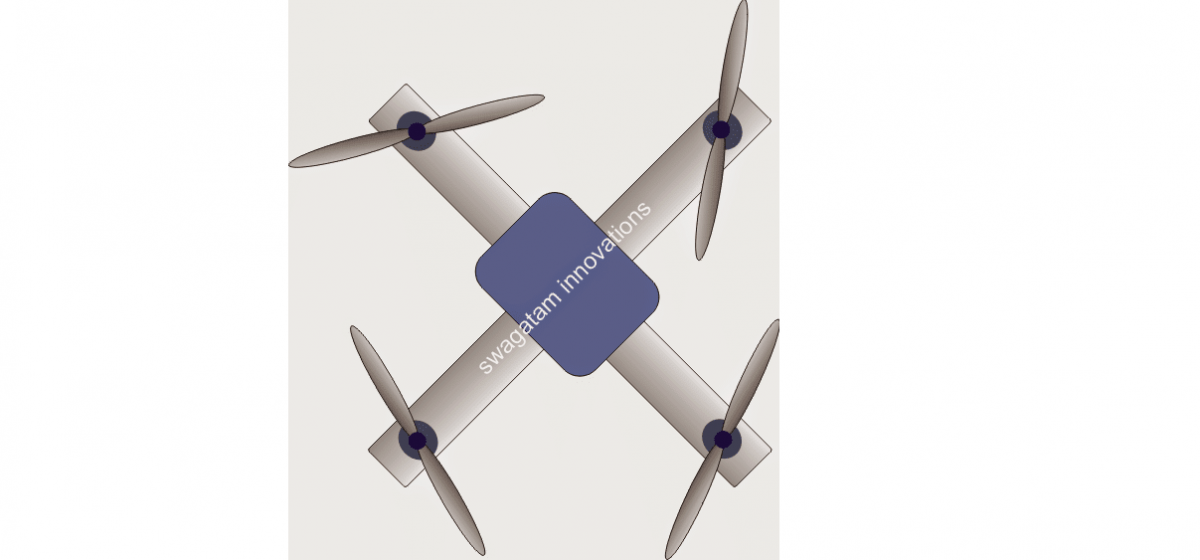
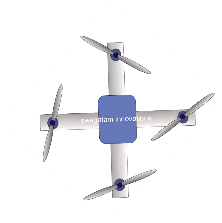
1) Basically the machine requires a firm and strong body, but extremely light in weight. This could be fabricated or assembled using hollow square aluminum extrusion pipes, by suitably drilling holes and fixing the frame with nuts and bolts.
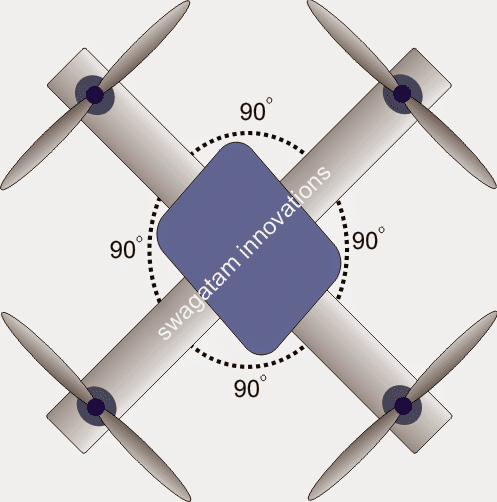
2) The structure should be in the form of a perfect "+" or a perfect "x", it doesn't make a difference as long as the angle between the "crossing" pipes are at 90 degrees each.
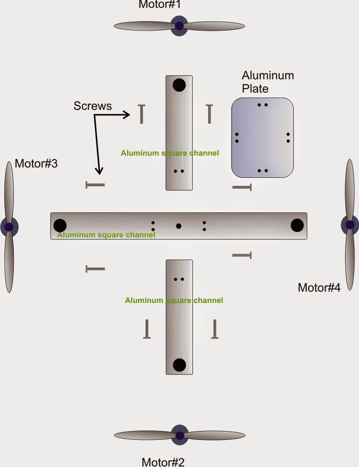
Basic elements needed for constructing a quadcopter can be seen in the following image:
Part Assembly Simulation
The rough animated simulation below shows regarding how to assemble the above shown elements together:
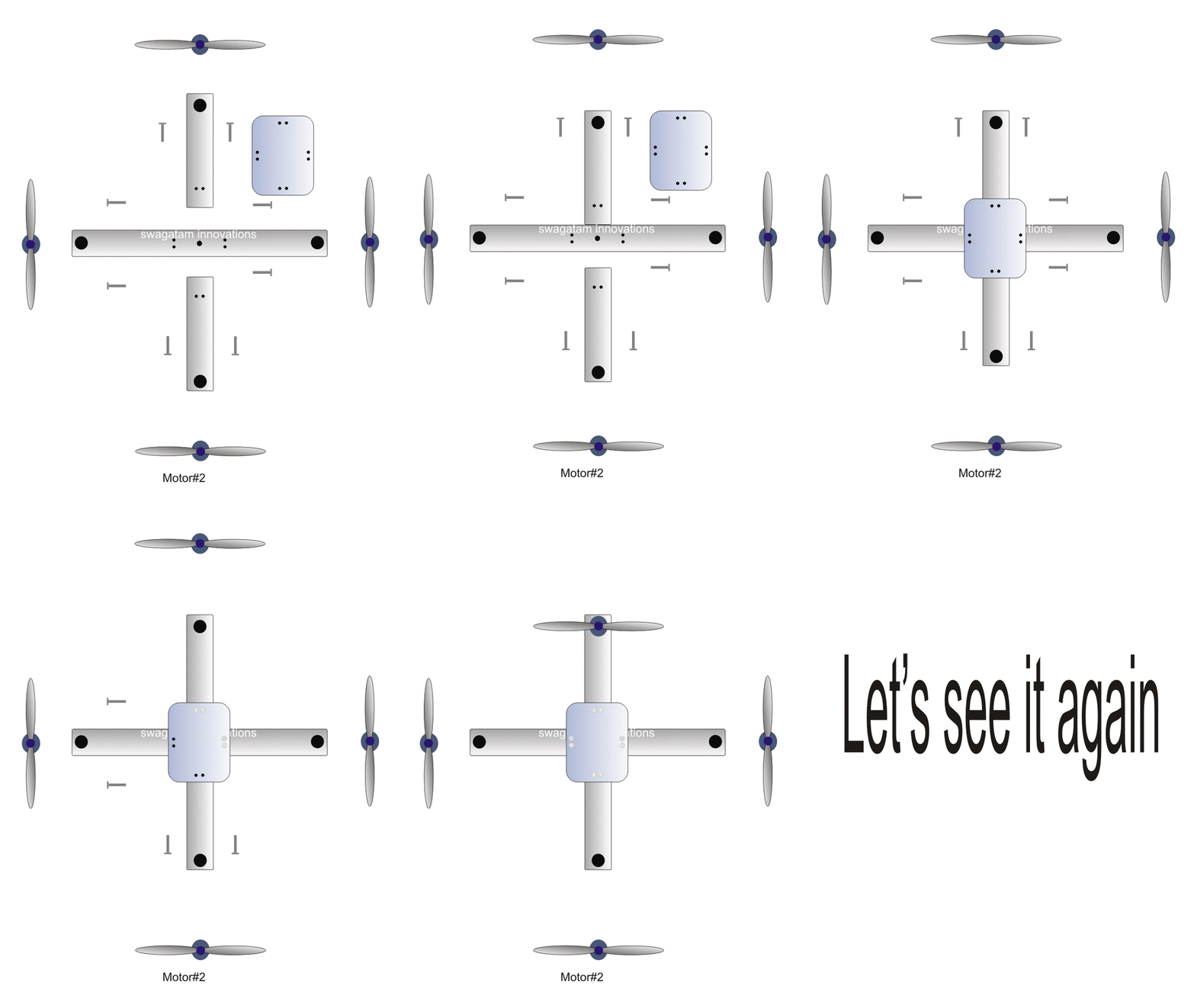
How to Construct Quadcopter Framework
The aluminum for the "+" frame can be acquired by appropriately cutting and sizing ready made aluminum extrusion tubing, as shown below:
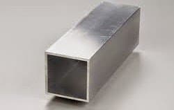
The size of the frame is relative and therefore is not crucial, you can build a wide frame with the motors fitted wide apart or build a rather compact frame structure where the motors are not too wide apart...although it must be ensured that the propellers are well aloof from each other for enabling better equilibrium and balance.
3) The "+" frame structure must be fitted with a square platform at the central section where the frame arms meet and cross each other. It could be simply a well polished aluminum plate appropriately dimensioned for comfortably accommodating all the necessary electronics and wiring.
Thus this central plate or the platform is basically required for installing and housing the electronics of the system which would ultimately be responsible for controlling your quadcopter.
4) Once the above framework is completed, the motors are required to fixed across the ends of the cross bars, as shown in the above figures.
5) It's needless to say that all the fitting work needs to be done with utmost accuracy, and perfect alignment, this might require the association of an experienced fabricator for the job.
Since everything in the design is in pairs, aligning the elements accurately won't be actually too difficult, it's just about sizing and fitting the pairs with as much similarity as possible, which will in turn ensure a maximum level of balance, equilibrium and sync for the system.
Once the framework is built, it's time to integrate the electronic circuits with the relevant motors. This will need to be done as per the instructions provided in the given circuit manual.
The circuit boards could be fitted on the bottom side of the central plate with appropriately housing or over the plate, again with an appropriate cabinet for enclosing it tightly.
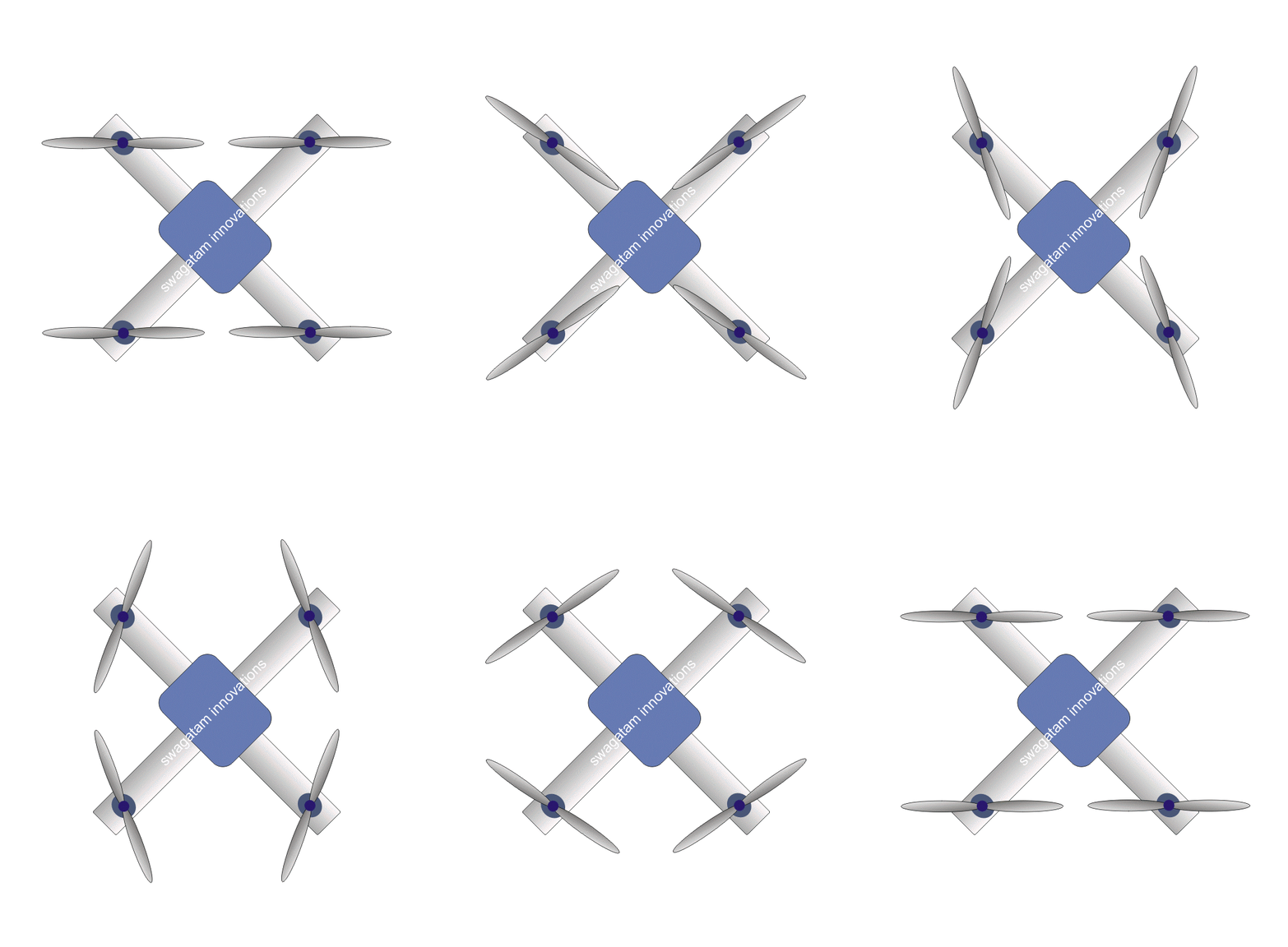
Understanding the Rotational Direction of the Propellers
Analyzing the direction of Rotation of the Motor propellers for a Balanced Lift-of:
Referring to the above animated simulation, the direction of rotation of the motor propellers should be aligned in the following manner:
It simply needs to be such that the motors at the ends of one rod should be identical but different to the other rod motor direction, meaning if one rod has the motors spinning in the clockwise direction, then the motors at the ends of the other complementing rod must be tuned to spin in the anti-clockwise. direction.
Please refer to the simulation above to correctly understand the counter-acting movement of the motors that may be needed to be assigned to the motors for ensuring a balanced take of
How to Control the direction of the quadcopter by controlling the speed of the motors.
Yes, the flying direction of the quadcopter can be tweaked and controlled as per your own wish and will by simply applying different speeds (RPMs) to the concerned motors.
The following images show how the basic speed transmission may be applied to the relevant motors in order to achieve and execute any desired flying direction to the machine:
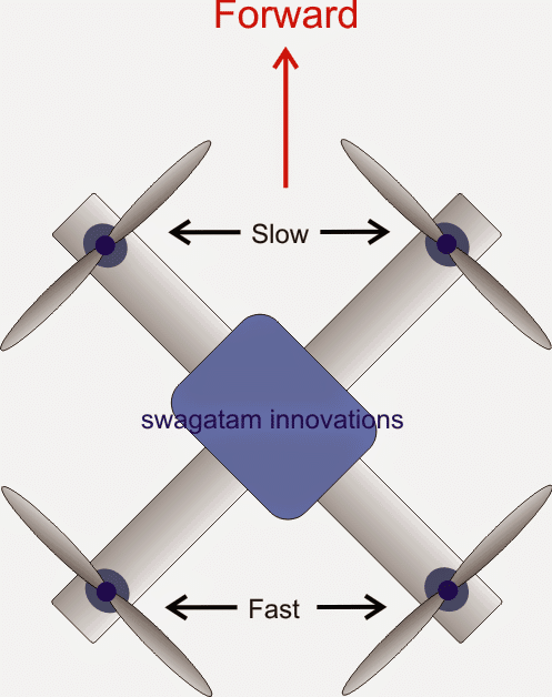
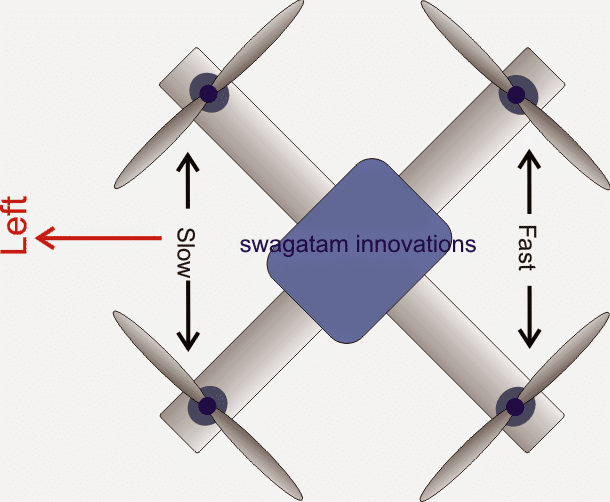
As indicated in the above diagrams, by appropriately decreasing the speed of a set of motors, or increasing the speed of the opposite set of motors, or tweaking the speeds as per ones own preference the quadcopter can be made to travel in the air in any desired specific direction.
The above images indicate the basic directions, such as forward, reverse, right, left etc...however any other odd direction can also be efficiently implemented by suitably adjusting the speeds of the relevant motors or may be just a single motor.
For example in order to force the machine to fly towards the N/W direction, the speed of only the S/E motor may be increased, and for enabling the machine to fly at the N/E direction, the speed of the S/W motor may be increased...and so on. It just needs to be practiced until the full control of the quadcopter becomes achievable and mastered by the user.
Designing a Practical Quadcopter
So far I have explained about the basic construction of the drone body and hardware, now I have explained how to make a quadcopter or a drone circuit quickly and cheaply using very ordinary components. In one of my earlier posts I have explained how to make a relatively complex and therefore efficient quadcopter flying machine without using microcontroller, for more info you would want to go through the following posts:
Remote Control Circuit without MCU | Electronic Circuit
In the present article we try to make the above design much simpler by eliminating the brushless motors and replacing it with brushed motors, and consequently making it possible to get rid of the complex BLDC driver circuit module.
Since the mechanical construction details of the quadcopter is already discussed above comprehensively, we will only deal with the circuit design section and learn how it may be built for flying the proposed simplest drone circuit.
As mentioned earlier this simple quadcopter requires only the basic RF remote control modules as shown in the below example image:
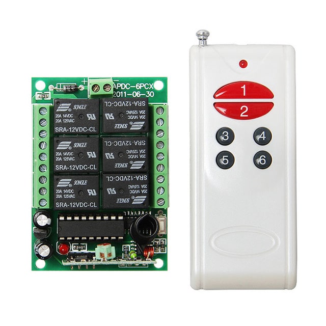
You will need to buy these RF modules from any online store or from your local electronic spare dealer:
Apart from the above mentioned RF remotes modules 4 permanent magnet brushed motors will be also required which actually forms the heart of the drone machine. It could be as specified in the following image with the given descriptions, or any other similar as per the required user specifications:
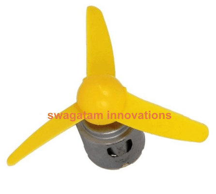
Electrical Specifications of the Motor:
- 6V = operating voltage (peak 12V)
- 200mA = operating current
- 10,000 = RPM
Parts List
- 1K, 10K 1/4 watt = 1 each
- 1uF/25V Capacitor = 1no
- Preset 10K or 5K = 1no
- Rx = 5 watt wirewound resistor, value to be confirmed with experimentation.
- IC 555 = 1no
- 1N4148 Diodes = 2nos
- IRF9540 Mosfet = 1no
- 6V Motor Brushed Type = 4nos
- Flexible wires, solder, flux etc.
- General purpose PCB for assembling the above parts
- 4 Channel RF Remote Control Module, as shown in the relevant images.
- Aluminum Channels, screws, nuts, plates etc as explained in the article.
- Battery as shown below:

How to Configure the Remote Control Receiver with the Motors
Before understanding how to configure the remote control receiver with the quadcopter motors, it would be important to learn how the motor speeds are supposed to be adjusted or aligned for generating the required left, right, forward, backward motions.
Primarily there are two ways a quadcopter can be enabled to move, which are in the "+" and the "x"modes. In our design we employ the basic "+" mode of motion for our drone, as indicated in the following diagram:
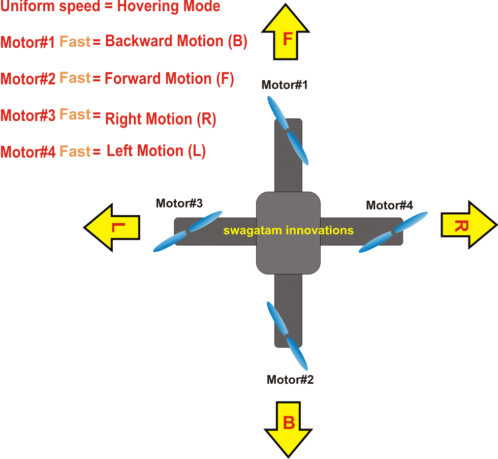
Referring to the above diagram we realize that we simply need to appropriately increase the speeds of the relevant motors for executing the desired directional maneuvers on the drone.
This increase of speeds can be enforced by configuring the remote control relays as per the following wiring diagram. In the diagram below we can see an IC 555 PWM circuit wired with the 4 relays of the remote control receiver module of the 6 relays (1 relay being unused and could be simply removed to educe space and weight).
Adjusting the PWM
As may be witnessed in the diagram, the PWM feed is connected with all the N/C contacts of the relays, which implies that normally the quadcopter would be hovering through this uniform and equal PWM feed, whose duty cycle may be initially adjusted such that the quadcopter is able to attain a correct specified amount of thrust, and altitude.
This may be experimented by appropriately adjusting the shown PWM pot.
How to Configure the Relay Contacts
The N/O contacts of the relays can be seen wired directly with the positive supply, so whenever a relevant button is pressed on the remote transmitter handset, the corresponding relay is activated in the receiver module, which in turn enables the relevant motor to get the full 12V supply from the battery.
The above operation allows the activated motor to gain more speed than the rest of the motors which allows the quadcopter to move towards the stipulated direction.
As soon as the remote button is released, the drone stops instantly and continues to hover in the constant mode.
Identically, other directional motions can be simply achieved by pressing the other assigned buttons, on the remote handset.
The topmost relay is for ensuring a safe landing of the machine, this is done by adding a current dropping resistor in series with the N/O contact of the shown relay.
This resistor value must be calculated with some experimentation such that the quadcopter hovers around a couple of feet above the ground whenever this resistor is toggled through the attached relay.
Circuit Diagram
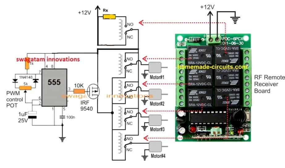
The shown relays are the part of the RF module receiver, whose contacts are initially unconnected (blank by default) and needs to be wired as indicated in the above diagram.
The RF remote receiver is supposed to be installed inside the quadcopter and its relays wired with the relevant motors and battery as per the above shown layout.
You can see a few connectors (green colored) which can unnecessarily add weight on the drone. You can remove them all to reduce weight, and connect the relevant wires directly to the PCB by soldering.
How the Drone Moves:
As explained in the above discussion, when a particular remote button is pressed, it actuates the corresponding relay of the quadcopter module causing the relevant motor to move faster.
This operation in turn forces the machine to move in the direction opposite to the motor which is being switched to rotate at the faster RPM.
Thus for example, increasing the speed of the south motor causes the machine to move towards north, increasing the north motor causes it to move south, similarly increasing east motor speed causes it to move west and vice versa.
Interestingly, increasing the south/east motors enables the quadcopter to move towards the opposite north/west that is in the diagonal mode....and so on.
Pros and Cons of the above explained Simple Qaudcopter remote control circuit.
Pros
- Cheap, and easy to build even by a relatively new hobbyist.
- Does not require complex joystick operations.
- Can be controlled using a single 6 channel remote control module
Cons
- Less efficient in terms of battery back up due to the involvement of brushed motors
- Directional speed is constant and cannot be varied through the remote control handset
- Maneuvering may not be smooth rather a bit jerky while switching the buttons.



Questions & Answers
Thanks
U r great
My pleasure!!
getting back to new project with in some days jackfranko here
getting back within some days with new idea will be meeting you very soon
sure, jack franko!
Sir I have a 27 MHz ROC car but i break all the wires of car and transistor circuit now I can't able to join them please tell me how to join motors, antenna and battery to circuit of car
Can I send photo of my car's circuit any how if u not understand my cars circuit?
Sahaj, sorry that would be difficult for me, because different RC toys have different wiring configurations, which cannot be judged by just viewing the pictures…
sir you didnt showed the connection to motor in circuit diagram..can you please tell me online sites where i can purchase motor and rf remote control..iam living in kerala..
please see the last diagram it has all the details regarding the motor connections with the remote relays
there are many online stores who sell drone related parts….I cannot specify a particular one…all are good.
I already found where to join motor and antenna wires
But still I don't found where to join buttery wire
Please help me any how
the ground symbols are all negatives of the circuit and need to be joined with the battery (-)…..and the positive of the battery will go to the +12V point.
Thanks very much I understand where to join -ive wire but still I don't understand where to join +ive wire and also to join the switch wire
Please reply the good answer I am very thank full to u
the battery positive will go through a switch and then to the indicated +12V arrow.
the power ON/OFF switch is not shown, you can add it yourself.
Thanks very much
I successfully attached all the wire of car
But the problem is now my car not going backward
So please give me the circuit diagram or any idea how to join all the wires in transmitter
you can refer to the following article for the required info:
https://www.homemade-circuits.com/2012/09/make-remote-controlled-toy-car-circuit.html
Where and how PWM circuit connected to the receiver?
Thanks
HELO SWAGATAM i really like this , am having 9v blushed motors four of them can that circuit above be used if not sir provide me with a circuit where i can use the 9v blushed motor to my simple quadcopter to fly. thanks very much for all your effort
Hi Davis,if your motors are specified to rotate at extremely high RPMs (3 to 5 thousand) as recommended for drones, then surely you can use them for the proposed application
the constant frequency maintains constant speed on all the motors which a little lower than the motors full speed, and the drone stays stationery,
when one of the remote buttons is pressed…the corresponding relay in the drone is actuated which connects the relevant motor directly with the supply and allows the motor to rotate at full speed, this causes higher torque for this motor while the other motors continue with the slower speed…and this in turn enables the drone to move toward the corresponding direction
please read the previous comment and the article explanation
How will it move up and down
altitude will be fixed and needs to be set at the beginning.
first of all u rocked…….really amazing and good post…..and i am doing this as my semester project but facing some problems.
Sir, i have a doubt that how and where we are going to connect the relay circuit in the quad copter …?
cz as mentioned in this post that the signal will be recieved by RSW434 and after going to HT12D it will be directly connected by 1n1,2and 3 pins of the DRV8313 IC which will rotate the motor…….. but where are we going to attach the relay circuit and 555 timer circuit in quad copter as mentioned above ….? kindly help me out ..and please sir kindly send me a full circuit diagram of quad copter cz then it will be easy for me to understand….i will be very thankful..
I appreciate your enthusiasm, but I think you did not read the article correctly.
DRV8313 is not used here, the motors are brushed type motors, and are directly connected with the remote relays of the receiver unit.
Please read and understand the concept correctly before you embark in the project otherwise you might fail to make it work
Nice
is it possible to make it with a camera on top??
No…
hello sir! this seems a really easy and good idea for minor project, can u tell me how much is it going to cost approximately? and how much time is it going to take?and are the components available online ?
hello sir! this seems as a really good idea for minor idea, can u tell me how much will it cost approximately and how much time is it going to take? and are the components available online?
Thanks Piyashi,….the cost could be anywhere from Rs.1300/- to Rs.2000/- but it cannot be less than Rs.1300/- for sure.
all the indicated components can be procured online….however, proceed only if you think you have understood the concept thoroughly and preferably get the assistance from an electronic expert while assembling
Oh brother, I wish to put our electronic components for the Dron aircraft and the way they are installed and connected to the board or circuit diagram of electronic circuit is very clear and simple to her and the guardian of her own. Thank you.
you are welcome!!
Pls Sir I don't understand the Rx in the circuit wot is it
when this relay is toggled, the 12V supply reaches the motors through Rx, reducing their speed drastically and this quickly brings down the drone towards ground and allows the user to get hold of it…..I am sorry the 12V supply is shown shorted and not through the N/O and Rx contacts…I'll correct it soon…
Sir I am interested to make a quadcopter with mini motors in the mobile phones.
Is it possible??
If possible what changes I could make in the circuits you explained.
Please answer me….
I am waiting for you.
hai sir I am Akhil
I am interested to make a quad copter with mini motor in mobile phones.
Is it possible??
If possible what change I could make in the circuits you mentioned.
Please replay me with details.
I am waiting for your response.
Hi Akhil, I don't think that would be possible because the motor may not have the required amount of thrust to lift the circuit board itself, especially due to presence of the relays.
Then which type motor can be used to make a small size quadcopter.
It should be big enough to at least be able to lift the circuit boards.
From which site i can buy rf remote control module?
search for “buy 433MHz Remote control module”
I needed the complete diagram and step to step of soing it, this way it will be more easier for me to build.
hey swagatam. i’m interested in your projects.keep teaching us
My pleasure David!
hey swagatam.thank you for your projects.May you teach us how to make a wireless computer controlled quadcopter please?
Thank you David, the idea that looks a bit complex and beyond the range of my expertise, still if possible I’ll try to figure it out.
Thanks.Is there any problem using a higher rpm motor like a 20 000 rpm?what change can it make on it’s capacity to lift objects like camera?
yes that’s definitely possible, if the thrust to weight ratio of the motor is sufficiently high. No changes would be required in the design, just the battery will need to upgraded according to the motor’s current rating
Thanks.Is there any problem using a higher rpm motor like a 20 000 rpm?what change can it make on it’s capacity to lift objects like camera?what is it’s maximum altitude and according to you what will be the good value of Rx
The lifting power will depend on RPM, propeller size, and the motor current, and its thrust to weight ratio (efficiency). The circuit will not any changes for this upgradation, as long as the motor current is not above 3 amps. in that case the relays will need to be accordingly upgraded.
Rx value will need to set with some practical experimentation.
Can it be possible to add a wireless 600g camera to the quadcopter?
Using brushless motor can make any change?
brushless motors will require special drivers, that’s the reason brushed motors are not employed here for the sake of simplicity.
how can i attach a non wireless camera to my drone
first test the drone in its basic mode, test its lifting power and then you can try loading a camera…
Can we use the same for small rc plane if yes please let me know it will be very helpful of you as I want to make a rc plane and I am not an engineer but highly interested in making rc plane my using mentioned circuit diagram.
An RC plane may be quite different to a drone and much complex than a drone, a drone is very straightforward to design and build but an RC plane may not be that simple, sorry I do not have sufficient data with me to assist you in building an RC plane.
what size an weigt of battery will a simple drone lift
any appropriate Li-ion or lipo battery will work, these are already well optimized.
Hello! would you mind writing down a list of all the components that are necessary for building a drone. Im doing a project on surveillance drones but im not really knowledgeable in the area. Your assistance will be greatly appreciated!
Hello, I have added the parts list, you can check it out.
sir my own motor have two wire,how can i connect it
please connect them as indicated in the diagram.
Thanks. I like this
But, I’d like to have the trasmitter
Thank you, the transmitter will come with the receiver as a set.
sir i am using your circuit for my project and got a few question here. will it not function if brushless motor were used? or does it come more complex? i was wondering if you use esc?
Maira, brushless motor being a 3 phase motor will require complex driver or ESC, so it won’t work with the above concept.
Or you may require the following things to make it work:
https://www.homemade-circuits.com/quadcopter-remote-control-circuit/
thank you !!!! you are very helpful.
You are welcome!
Sorry sir..
How can I get the Rf remote receiver?
You can get it by searching online!
hello mr swagatam. im building the circuit on my own. is it possible if different remote control is use?
Hello maira, any remote control will work as long as it controls the relay as per the given explanation.
thank you sir!
Hello mr swatagam. Do you have schematic diagram on making rf remote control on your own? And possibly the one that can control the receiver?
Hi Nur, I have a short range homemade RF remote as shown below, but it cannot be used for controlling a drone
https://www.homemade-circuits.com/how-to-make-fm-remote-control-using-fm/
Hello sir. Is Rx 5watt wirewound resistor is the potentiometer wirewound?
Hi Maria, it can be a simple wire wound fixed resistor…pot is not recommended.
what does it meant by ‘value need to be confirm with experimentation’? can you enlighten me?
It means the value must be adjusted to a level which will cause the motor speed just enough to hover above the ground.
Hello sir may i know what value you put for wirewound resistor?
Maria, you will have to set it as per the motor RPM, and ensure the resulting speed allows the drone to just hover a few feet above the ground.
Hello sir, may I know how to make all of the motor that were connected to the relay function simultaneously?
sorry I could not understand your question?
I hve a problem. I have connected all the circuit but the motor are only operating one by one based on the respective button.
If you connect the relay exactly as shown then all the motors will work together normally, and individual motors will work with PWM in response to the transmitter button press. Please check if you have correctly used the N/C and N/O contacts of the relay. For more info on relays you can refer to this article:
https://www.homemade-circuits.com/how-a-relay-works-in-circuits-how-to-connect-it/
Hie! If possible will you be able to provide a simple circuit diagram of a quad copter using the game pads, say of a play station.
The thing is the RF module kinda hard to get that is from where i.m for the mean time.
Just want to be able to build something which can actually fly for just some seconds nothing much. Thanks in advance!
Dear sir swagatham
Namaskar I am raghu.k deputy superintendent of police technical retd from tamilnadu police career spanning 38 years of service. Served in various units including research and development with lot of projects to my credit I was awarded meritorious police president medal and chief minister,s medal for devotion to duty and projects. I am hobbiyists electronic enthusiast. Doing lot of projects and hobbies. Accidently when I retired police computer wing in dec 2019 my colleague want some ideas on drones .they want to make one.it is at this juncture that started surfing the net to look into sites where kits are available. This envinced interest why not I do one I bought some motors propellers lippo btys etc but except rec and transmitter. I have basically design one frame with propellers a nd motors but I could not succeed. It is whenni stumbled upon do more studies. I landed on your website with s project well super swagath mind-boggling woderful I dear neat explanation.
Great now most of my doubts are cleared .hope to succeed with your inputs.i would be great ful if you can post your cell no on my mail id so that have a live interaction specific to drones. I will not trouble you often sir kindly post it reply to mail so I can bebin touch with you boss
Regards
Raghu
Chennai
9445466005
Thank you Dear Raghu ji, Namaskar. Today flying drones has become so easy because the batteries and the motors have become highly efficient. However, to make sure the motor and the battery are correctly implemented and the drone is able to fly optimally, it is necessary to calculate the parameters appropriately.
The main criterion that must be taken into account while building a drone is the weight to thrust ratio, which must be 2:1. Meaning the lifting power of the motors must be two times higher than the total weight of the drone. For this, we have to make sure that the body frame of the drone must be as light as possible, and comparatively the motor and the battery must be rated sufficiently higher with their specifications. Additionally we have to make sure that the battery Ah rating is appropriately selected with regards to the motor specifications. For a Li-Ion battery we can assume the discharge to be 0.8C meaning 80% of its Ah rating. And therefore the motors must be rated according to this current value. For example if we have 4 motors rated to consume 4 amps, then the battery must be rated at 5 Ah or slightly more.
So basically if you follow the above rules then simply by connecting 4 motors and a battery to a cross frame will allow the system to be air borne and the system will be able to hover at some height until the battery weakens causing the drone to slowly descend towards the ground.
I hope these basic facts might have clarified some doubts regarding how to build a simple drone at home successfully.
I am sorry a telephonic conversation may be difficult for me due to the huge number of comments that I have to answer, and many other website related work.
Good morning have a great day nice for wonderful inputs and guidance.valuable ideas.i will keep in mind and sure I am doing it . Send the video of my airborne drone.surely it will be wright brothers flight.????????????????. It may take some time due online delivery of the products suggested by in the said project.it will be a surprise video.keep rocking with new ideas we hobbyist learn from experts like you. Thanks swagatham ji shukriya.
Regards
Raghu
Chennai
That sounds great! I hope you succeed with your project, let me know if you have any more doubts, I’ll be happy to help! Keep up the good work.
How do you know the right circuit bird to choose,and what Cindy of circuit board do you need to make a drone.
Dear Sir,
1. I have 3.7V 51000 rpm motors can I use those in same circuit
2. Could you pls help me with relay specification
Tush, the relay contact rating will depend on the motor current or the mAh specs.
If I made this drone, and if I build another Bluetooth Controlled RC car, then considering weight and other modifications, can I attach them together( car below the drone ) and still make both the devices carry out their individual functions? Like car + drone or vice versa.
No, sorry that may not be possible with this drone concept.
If possible, can you please provide me a short basic idea on how can I make that type of drone which will work with the rc car?
You can use the same idea as expressed above, just go for higher rated motors and higher rated battery. Because to lift the RC car, the motor and the battery will need to be substantially powerful
Hello sir, is the use of gsm model a nessesity in building the drone, and also how do I connect the receiver to the flight controller!?
Isaac, a GSM model provides accurate control of the drone and allows the use BLDC motor making the system extremely efficient.