In this post I have explained the fundamental methods of triggering a triac, and also discuss the right way to connect the terminals of a triac.
Triacs are solid-state bidirectional thyristors that can switch across both the AC half cycles on a 120-volt or 240-volt Ac power system.
A triac could be activated (switched on and latched) with the AC line both synchronously or asynchronously.
However, if the triac's gate terminal current drops just below its lowest holding threshold, it will be switched off instantly at the completion of each AC half-cycle (180 electrical degrees).
WARNING: ALL THE CIRCUITS DISCUSSED IN THE FOLLOWING ARTICLE INVOLVE LETHAL 220 V MAINS AC. THEREFORE YOU MUST BE EXTREMELY CAREFUL WHILE USING AND TESTING THESE CIRCUITS, MAKING SURE THAT YOU APPLY ALL THE NECESSARY PRECAUTIONS DURING THE PROCEDURES. ALL THESE CIRCUITS ARE STRICTLY RECOMMENDED ONLY FOR THE EXPERTS.
Synchronous vs Asynchronous Switching
In an asynchronous switching, the triac is triggered ON randomly at any point of the phase cycle.
Due to this, asynchronous switching of triacs can produce substantial radio-frequency interference (RFI), especially at the first switching cycle.
In a synchronous triac switching, the switching periods consistently arrive on at the same moment for each AC half-cycle (typically right after the zero-crossing period) and therefore produce negligible RFI.
All the circuits I have I have explained in this article use asynchronous power switching. Figures 1–8 depict a number of asynchronous triac power-switching circuits for elementary ON/OFF AC line switching.
How to Connect a Triac
A triac has 3 terminals, which are MT1, MT2, and the Gate. The MT stands for main terminal.
Therefore, the main terminals MT1 and MT2 are used for switching heavy AC mains operated loads, through 220V or 120V AC mains supply.
This switching happens in response to a small DC voltage applied to the gate terminal of the triac.
New hobbyists often get confused and ask the question how the MT1 and MT2 terminals should be configured with the AC load and through a DC at the gate?
Remember, the correct method to connect the triac MT1 amd MT2 terminals is by ensuring that the AC load is always connected in series with the MT2 terminal, and the MT1 is connected directly with the other AC line of the mains supply.
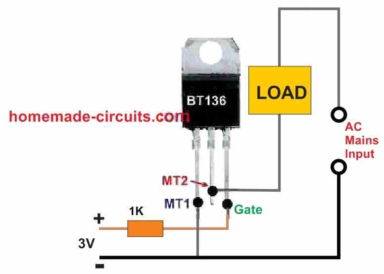
Also, it is extremely important to note that the AC line associated with the MT1 terminal must be also linked with the negative or the ground line of the DC supply, which is being used for triggering the triac gate.
Failing to do this will not allow the triac to respond to the gate signals.
Triac Switching
A basic AC power switch using a triac is shown in Figure 1.
This triac circuit can be used to control the flow of AC power to lamps, heaters, motors, and a variety of other appliances and devices.
However, the triac for this circuit should have the appropriate power handling capacity to reliably switch AC power for the particular application.
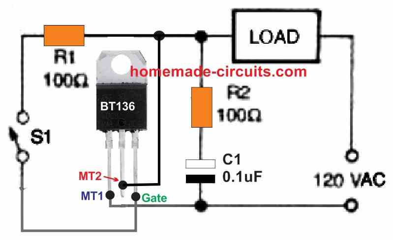
All of the components in this article's schematics were chosen to switch only 120 volts, 50/60 Hz AC.
During the time the switch S1 is open, the triac is turned off and functions as an open switch.
However, when switch S1 is closed, it operates as a closed switch which is powered from the mains AC line via the load and R1 right at the start of each AC half-cycle.
When the triac is turned on, its main terminal voltage decreases to just a few hundred millivolts, thus R1 and S1 draw relatively negligible current.
Please remember that as soon as S1 is initially closed, the triac's turn ON threshold is not synchronized with the AC line, but it gets synchronized with the successive AC half-cycles.
The snubber network formed by resistor R1 and capacitor C1 reduces voltage spikes which develop whenever inductive loads are switched and when current and voltage are out of phase.
Most of the triac circuits discussed in this article incorporate snubber connections.
The triac works like a power switch that may be actuated by DC supply derived from AC supply, as shown in Figure 2 below.
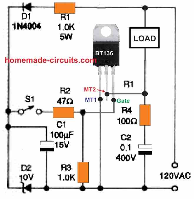
Each positive line half-cycle charges capacitor C1 to +10 volts via resistor R1 and Zener diode D1.
When S1 is turned ON, the charge from C1 initiates the triac. Here the resistor R1 always gets exposed to approximately to the whole AC line voltage.
As a result, it demands a significant power rating (5 watts in ous case).
Due to the fact that all portions of this circuit are "active," it can create a fatal electrical-shock hazard.
Furthermore, since it lacks an isolator or complementing mechanism, this circuit is impossible to integrate with outer control circuitry.
Isolated Triac Control using Opto-Couplers
The next Figure 3 below demonstrates how to modify the circuit in Figure 2 to make it easier to connect with external control circuits.
Bipolar junction transistor Q1 is used in instead of switch S1 and is operated by the output stage of an optocoupler (or optoisolator) IC1.
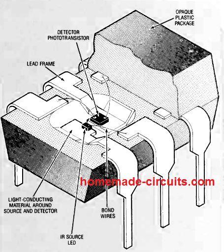
An infrared light-emitting diode (IRED) is optically linked to a phototransistor in this system. Any of the commercially available transistor-output optoisolators can be implemented in these application.
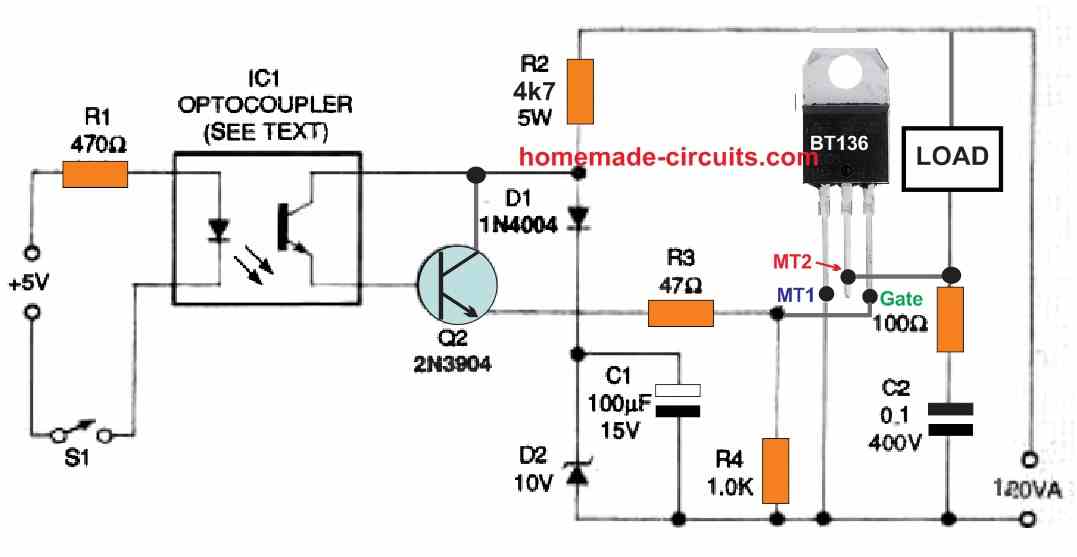
The opto couplers like TIL111, TIL 112, 4N27, and 4N28 are among the several. Using resistor R1, a 5 volt or larger DC source could be used to power the optocoupler.
Only after switch S1 connects the input circuit supply to a 5 volt or larger power source, the triac is switched on.
Typical isolation values (Viso) for optocouplers are 5000 volts AC, with some having ratings as large as 7500 volts AC.
This implies that the DC input circuit is completely isolated from the triac output side circuit powered by the AC line.
By substituting S1 with an appropriate electronic detector, this fundamental triac switching circuit may be modified to provide any desired type of automated "remote" triac switching.
Figure 4 below shows a modification of the circuit seen in Figure 3.
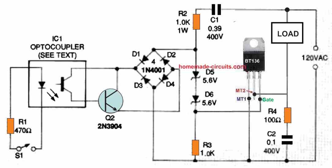
Using capacitor C1 and the series resistor R1, along with the back-to-back Zener diodes D5 and D6, the triac is AC actuated on each line half-cycle in this design.
The amount of the triac gate current is determined by C1's AC line impedance, while the power dissipation of the capacitor C1's is almost around zero.
The series connection of Zener diodes D5, D6, and R3, that is loaded by transistor Q1, is coupled across the bridge rectifier built using diodes D1, D2, D3, and D4.
The bridge is essentially open while transistor Q1 is off, and triac TR1 switches on following the onset of each AC half-cycle.
As soon as transistor Q1 is turned on, an almost a short circuit like condition is developed across D5, D6, and R3, which shuts off the Triac gate current, eventually turning off the triac TR1.
The optocoupler from the isolated external input stage drives transistor Q1, thus the triac is typically on, but it switches off as soon as the switch S1 is closed.
Using DC for Triggering a Triac
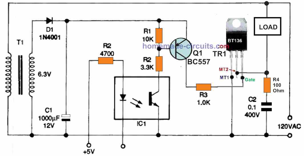
Figures 5 and 6 as given below, illustrate how to use a DC power source from a transformer power supply and a transistorized switch to activate a triac AC power switch.
When S1 is closed, both the transistor and the triac are both turned on, and as soon as S1 is open, both the devices are turned off.
In Figure 5, switch S1 can be substituted by a sensor device that can detect and respond to physical changes.
Transistor Q1 can be a BC557 transistor, not shown in the diagram.
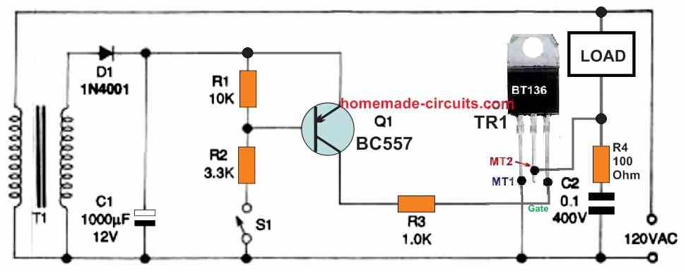
For example, If the ambient temperature decreases below a predetermined level, a thermistor, can be incorporated to activate the triac circuit.
Similarly, photoconductive cell can be installed to detect light levels, a pressure sensor may detect changes in air or liquid pressure, and a flow metre can react to variations in liquid or air flow rate.
Please be cautioned that the Fig. 5 circuit, is "live" and poses a lethal shock threat.
Figure 6 below demonstrates how to adapt the Fig. 5 circuit to use an optocoupler for its control.
This circuit could be actuated through a completely independent and isolated external circuit due to the presence of the optocoupler.
Triggering through Unijunction Transistor
Figures 7 and 8 as shown below, depict many different methods for triggering a triac through a completely isolated external circuit.
A unijunction transistor (UJT) placed in a pulse-generating relaxation oscillator provides the triggering operation in both of these circuits.
The oscillator circuit, which contains UJT Q2, provides the triggering pulses in these two circuits.
It works with a frequency of many kHz and feeds its output pulses to triac's gate via the pulse transformer T1, that ensures the intended isolation.
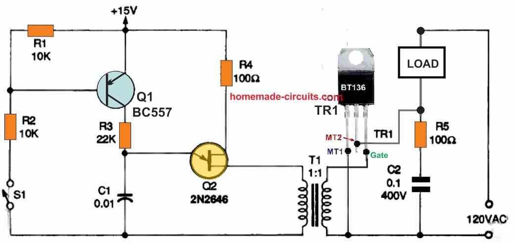
During the ON periods of the oscillator, the triac is turned on immediately at the start of each AC half-cycle due to the UJT device's relatively high working frequency.
With a resistor R3 is connected between the emitter and the base B2 of the UJT Q2, and a capacitor C1 hooked up between the emitter and the base B1, the UJT Q2 now works like a relaxation oscillator.
In this configuration UJT is able to switch rapidly to charge/discharge the capacitor at high speeds, as soon as the capacitor voltage reaches a certain threshold.
The time consumed by the capacitor to discharge could be evaluated, using the sawtooth's frequency calculations which is around 1/ time.
Since Q1 is in series with the UJT's primary timing resistor R3 in the Fig. 7 circuit, the UJT and the triac only switch on when S1 is closed.
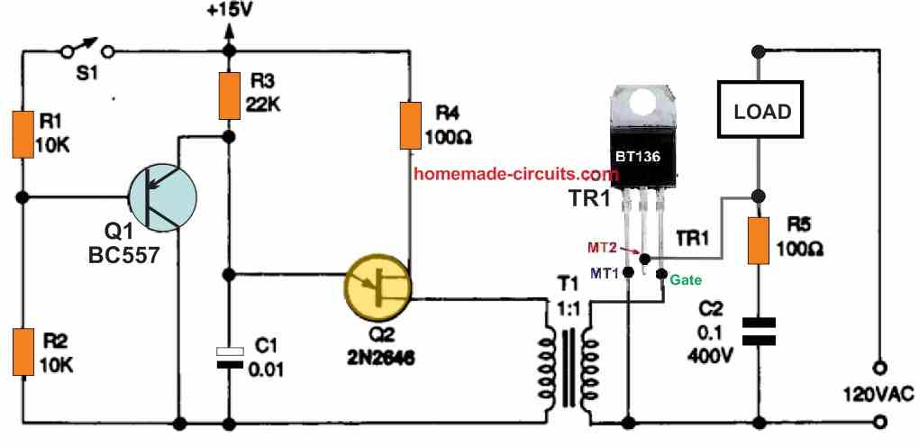
On the other hand, in Figure 8 above since Q1 is in parallel with the UJT's primary timing capacitor C1 in the Fig. 8 circuit, the UJT and triac only switch on when S1 is open.
S1 could be substituted by a sensor or transducer in each of these circuits to provide an automated power-switching operation as mentioned previously.
The Q1 in the above figure should be an NPN transistor, such as a BC547.



Discussion & Solutions
Hi Mr. Swagatam, I am looking for a voltage sensing circuit to control a relay to start my solar inverter when the solar cell reaches 15.5 V. do you know of anything suitable ??
thanks in advance
kind regards Harry Vincent
Hi Harry, you can apply the following circuit for controlling the solar panel voltage:
you will have to adjust the 10k preset to set the exact tripping voltage level.
Many thanks for the circuit Swagatam. Much appreciated
Thank you Harry! Glad you liked it!
The above descriptions are wonderful. Please I would like see a schematic involving triac for regulating ac motor or as light dimmer capable of controlling up to 2000w worth of power
Thank you Moses. I already have a light dimmer related article, whose triac can be upgraded for controlling heavier loads.
Thanks sir,I have seen them and they are very useful.
You are welcome Moses!
Pardon my ignorance, but I missed the point of why one would want to do this and not just use a mechanical switch. Perhaps remote controlled switching? But many of the circuits do have mechanical triggers, so I’m still confused what the benefit is.
It is because mechanical switches are bulky, prone to wear and tear, and they make noise and sparking while operating. The small switch shown in the circuit diagrams are only for indicative purpose, they can be actually replaced with sensors or other forms of external signal inputs.
Thank you!
grate information
thank you!
Good morning sirI’m trying to figure out the alternator booster diagram where the traic circuits posted
Hello nosa, here’s the link you are looking for:
https://www.homemade-circuits.com/generatoralternator-ac-voltage-booster/
Dear sir,
I have a doubt that, normally triac needs +ve and -ve gate supply to make conduction of both SCR’s, but in your circuit (First circuit) you gave 3v dc through 1k resistor. Can you please clearly explain how triac operating here.
Hello Venkat, triac will switch an AC signal only when a DC is applied at its gate….a 0V at the gate will turn OFF the triac at the zero crossing of the AC cycle, while a negative voltage will turn off the triac instantly regardless whether the waveform is at zero crossing or not.
Dear sir,
I have few doubts , please give me some clarity regarding my doubts
In my circuit, gate is negative (ground by using IC) and here T1 connected to both phase(230v AC) and 5v dc from rectifier circuit and T2 connected to single phase motor . Here capacitor is connected between gate and T2.
When ever I want to turn on triac, I will supply 5v from micom to IC then IC output will be grounded(gate terminal)and triac turned on till micom supply is there.
My question is
1) Here T1 connected to both phase and 5v dc . Means here we shorted Ac and DC lines. Is this acceptable?
2) what is the role of capacitor here.?
3) How trigger happening here.( I want to know how triac differentiate ac and dc signal when gate connected to ground)?
Sir you didn’t understand my doubts please send me your mail ID i will share circuit and explain it properly
Sorry
*****capacitor connected between T1 and g
ate
Hello Venkat, I did not understand your question. My email ID is given in the contact page. Please make sure the schematic is drawn correctly.
Can triac based dimmer switch be used to drive 120ac load through 220 acv mains by mere adjustment of the potentiometer to 120acv
It can be tried, but I won’t recommend this, because although the voltage could be reduced to 120V, but the peak can still remain at around 300V.
How can I build ac to ac converter that do the job more effectively without the use 220 to 120acv transformer. I need it to drive 115acv rated air conditioner cooling fan.
That is not possible without transformers. It can be possibly done through an SMPS circuit but that would be a lot costlier and much complicated
Hi Swagatam;
My switching voltage is DC 5V to the gate pin of BT136 and load is a AC 220 heater resistance less than 2 Amps. Please advise proper circuit for that. And also I think DC (-) ground and AC neutral poles should be connected together in the circuit. Thanks a lot.
Hi Suat,
are you trying to build a PWM heater controller circuit. I think the better option would be to use a light dimmer circuit instead, which can be compact and very reliable.
Thanks for quick response, my aim is briefly; first of all I will use dimmer to the heater resistance since it causes dry air when heats full capacity then I have been using pic16f877 to control lm35 for environment temperature to keep it between 36 and 38 degrees so the pic16f877 will trigger the heater resistance thru its 5 V DC output if temperature is below to run the heater or over to cut-off.(egg incubator) Kind regards
OK, so you want to know how to connect the triac with the 5V trigger source? right? In that case you can use the connections as given in the first diagram of the above article.
Hi Swagatam;
Referring to above first diagram as seen trigger voltage is 3 Volts so then to use 2 diodes after 3 volts trigger source is better in case that if AC reverse voltage is applied to the circuit.(I mean if inadvertently MT1 is live and MT2 is neutral connected) or not necessary – Thanks
Hi Suat, diodes are not necessary according to me. I have never used diodes at the gate of a triac and my circuits never had problems. Internally the triac is designed in such a way that reverse voltage from MT1 can never reach the gate.
Excuse me Swagatam. Please let me explain my concern: As we can see at the diagram DC (-) 3 V and AC mains input voltage are both of them connected to the MT1 and I assume that MT1 AC voltage is not live but neutral. I feel as if our DC power supply may be subject to be damaged since it will be in contact of AC voltage. Or in other words in case we connect live pole of AC main inputs to M1 and DC (-) I think then 3 V DC transformer may be damaged. Or simply it is possible to say that either live or neutral but only one pole of AC 220 may touch to the any pole of the DC transformer and no damage risk, no problem. Kind Regards
I can understand your concern Suat, but you don’t have to worry at all, because when a mains operated triac is connected with a DC circuit it is connected in this standard way only, there’s no other way. The LIVE/Neutral does not matter, you can connect the LIVE to MT1 and neutral to the load still there will be no damage to the circuit. But the only thing is that the entire circuit will float with dangerous mains AC and if you touch anywhere on the circuit in switched ON condition you may get a lethal electric shock….but any other electronic parts can not get damaged for sure, because I have myself built this configuration many times without any damage to the circuit.
The transformer secondary/primary winding are fully isolated from each other so the mains from the triac can never enter the transformer primary side.
Still if you have any fear, you can add a diode on the gate of the triac, as recommended by you earlier.
Hi Swagatam;
There is a dimmer circuit with BT136 but another BT136 will switch that dimmer circuit. Please advise if switch circuit would be in serial connection or parallel to the dimmer. Thanks and regards.
Hi Suat, the two circuits along with the load must be in series. However, I have never heard of this concept using two light dimmers in series, so not sure how it will work.
thanks too much I realized that my test circuit in serial did mislead me since there had been open contact on it however now it has worked best regards
Glad it is working now!
Sir,
How would I modify the circuit in fig 3 to control either 12 VAC or 240VAC ?
James, when you feed 12V AC at the input it will control 12V AC, when you feed 240V AC at the input it will control 240V AC, you can use a DPDT switch to switch between the two input supplies.
Hi Swagatam, thanks for the reply . I think I didn’t frame the question properly . What I would like to know is what component values would need to change to handle a voltage of either 12VAC or 240VAC ? I’m not asking for a circuit to handle both values with one circuit. I would be building two separate circuits to be used individually for each respective voltage to switch on entirely different loads. Thanks again.
Thank you James for the explanation. You can use the same circuit values for both the versions except R1. For 240V R1 will be 22K 5 watt, and for 12V R1 can be removed entirely and replaced with a wire link.
Hi Swagatam;
Today I used pic programming with 16f877a and triggered the BT136 gate thru DC 5 V like flip flop led circuit. The result was successful and as a load 220 AC bulb was on and off. Referring the first diagram I need your confirmation about the below matter. I did care that in my circuit, MT1 was connected both of (-) DC ground and AC mains neutral side. Now the point and my question is; Let’s say somebody changed the direction of 220 power plug and now MT1 is live and also in touch of DC – pole. In the case of this situation there is no problem or circuit would be damaged? Best regards
That’s great Suat, I am glad your circuit was successfully built.
As far as my experience goes and my knowledge goes, the polarity of the LIVE neutral in the first circuit does not matter, Even if you connect the LIVE or the phase to the ground side of the circuit there will be no harm done to the circuit, but yes the entire circuit will float with AC mains and will produce a lethal shock if any part of the circuit is touched with bare hands. But the circuit will not be damaged.
Hi Swagatam;
I have seen the info as “Logic Level” and “Sensitive Gate” for the triacs BT136-600D and 600E. Please advise if those are the same for simple switching purpose or not.
Thanks and regards
Hi Suat,
Sensitive gate triacs are those triacs which require very less current at their gate for operating. But I am not sure what logic gate triacs are, because all triacs can operate using a logic gate or a logic signal. They all can be used for simple switching purposes.
Hello dear Mr Swagatam
I am using a triac as an on/off switch
I drive it with a moc3021z and my load is a 220v led string . When i stop triggering moc3021z my led starts blinking . How can i fix this issue ?
Thank you♥️♥️♥️
Hello Ehsan, Did you build the circuit according to the schematic given in the datasheet of the MOC3021?
Try connecting a 1uF capacitor across the input triggering terminals of the MOC3021 and see if that help.
Hi Swagatam;
Duty of my circuit; to switch a 220 V AC bulb by BT136 and lights a led on by a NPN transistor (emitter voltage is 5 V DC). However, although no base trigger voltage I measure about 160 V DC at the output of the transistor. So I need your commentary-Best Regards
P.S.: BT136 Neutral and DC ground are common as known.
Hi Suat,
Since we have AC mains line connected with the DC circuit, all the points in the circuit will float with mains AC, or at least there will be some leakage AC floating across all the points. The meter has an high input impedance therefore even the leakage AC mains will be indicated on the meter as a high voltage.
Thanks Swagatam;
What I understand from your commentary; “there might be shock hazard but technically no problem on the circuit.”
Kind Regards
Yes that’s perfectly correctly. There may be floating voltage which may not affect the circuit but can produce lethal shock if touched
I am sorry Swagatam;
After I sent the second message I have checked the circuit although there is no trigger voltage to the base of the transistor led is always ON. Kind Regards
Hi Suat, where did you connect the LED? Please connect it in series with the gate resistor of the triac
Excuse me but I am confused;
As I understood from your above suggestion the led will be on whenever the triac is on
Whereas I do not them (220 AC bulb and the led) on at the same time. Bulb will heat the environment and sometimes the led which resembles the fan will be on free from the triac activity. Best Regards
Yes the LED will be ON when a voltage is applied to the gate through the LED which will finally enter the MT1 lead, which is the ground lead of the triac. If you check the MT1/Gate connection with a multi-meter you will a find a continuity across these two terminals, so if a voltage is applied to gate it will pass to the MT1 lead.
Hi Swagatam;
The subject is complicated for me and may be I did mislead you but I got the answer of my question by trying and getting wrong. I have realized that when I placed the led to wrong side of the NPN transistor it is always ON even there is no base voltage. Kind Regards.
Hi Suat,
If you are using the emitter of the NPN to trigger the triac, then the LED can be connected in series with the emitter pin of the transistor along with a series resistor. The anode of the LED will be towards the emitter, cathode will be towards the triac gate.
Hi Swagatam;
In my circuit there are 3 bulbs (220 AC) controlled by BT136 and BT136 is being driven by PIC16F877A (working voltage 5 V DC). LM35 cheks the heat and if it is above 38 degrees C then BT136 is OFF but if it is under 36 degrees C then BT136 is ON. My problem is there are to much blinking events between the 38 and 36 degrees. Plase advise if those blinkings would damage the BT136 or not. Regards
Hi Suat,
You can try connecting a 470uF/25V capacitor between gate and ground of the triac and see if that helps or not.
Hello Sir
i am facing a Triac (BTA12 -800) failure with my remote circuit , used pic16f676 with capacitive ( transformer less ) power supply & MOC3021 opto coupler with Triac for control AC220 v , From total 7 Triac i used 5 Triac for for of/off without snubber & 2 Triac for fan speed control with snubber calculation. i placed all Triac at very nearest area i mean all touch to gather with each other & no sort of it’s heat sink with each other. So what the reason of failure , it’s placement problem ? Or may i used some line filter & any other spike protector element in primary side.
If u used snubber for on /off then it create problem of flicker on electronics led driver load ( due to main capacitor after bridge is charged ) .
Hello Nil,
The BTA12/800 is a very powerful and rugged triac and will never burn, unless the load exceeds 800 V/ 12 amps, or if the triac overheats or if the triac itself is a duplicate part.
If you are using many triacs together make sure there bodies do not touch with each other.
I hope you are not using a capacitive power supply for the PIC16F, I hope you are using a 5V regulated AC to DC adapter for the PIC.
The triacs are not sensitive devices like MOSFETs so placement is not the problem.
If your load side is not using above 800 V or above 12 amps, and if the triacs are not over heating then possibly the triacs are duplicate and faulty in nature.
Dear Sir
Thanks for prompt reply. My load is become house hold tube light & led driver tube light & regulars ceiling fan 500 ohms with BTA12 800.
instead of it can u give me other parameter by which i will be gudge that its origin.
I will take care of SMPS 5 v reg instead of Capacitive with PIC 16F.
After this all change does it require to add any spike suppresser like Line filter and 0.1 X2 type cap in input circuit?
Hello Nil,
If you have taken care of the mentioned things then there’s no need of any snubber for the triac BTA12 800.
By the way the MOC circuit itself has a snubber network added across the external triac.
Thanks
How can we judge that Triac is original Or dummy. Any test method. May i check its break down?
There is no need to add line filter in input side if we go with +5v Regulated SMPS ?
It can mostly be judged by its bad printing and poor external finishing. For practical testing, you can setup the first circuit from the above article, and test it with a heavy AC load.
If your load is not a high frequency type load then no need to add any filter. However if you feel it needs to be added to can go ahead and add it.
Thanks
ok clear all things.
Dear Sir
i am redesign old remote circuit with 5v smps ( LNK switch of powerint) with isolated , but i have one confusion that it becomes isolated with PIC 16F series ic Vdd , but in my circuit i am also using zero crossing detector of fan speed synchronous, & for that i used one Polyprelene cap of 400v & current limiting resistor is in series with Bridge & output +ve voltage goes to 4n35 opto’s led via also one resistor & finialy opto’s transistor is connect with +5v generate from smps & that opto’s collector direct goes to as a zero-crossing signal via one resistor to PIC 16 ic. Is this safe ? kindly suggest zero-crossing method use for PIC16 ? Is this fully isolated now Or may be Bridge -ve terminal which are connected to the Opto led Cathode create problem to enter line nutural into secondary side of 4n35 ?
Hi Nil,
without seeing your schematic it can difficult for me to suggest a circuit diagram. However I think you can try the following design for powering your PIC circuit through a zero crossing circuit. Let me know if it helps or not:
Dear Sir
please say which optocoupler i am using in your image .jpg ? It help full for me..i want to uoload my finial schamatics to you. Please give me guidlines because in past i done hevay loss with prodcutio. Second my interest is to fitting this kit it inside house hold’s board instead of seperate board..So while this kit goes inside exiting board ,does we calculate some other parameters like mechinical switch spikes or any other spike inside baord will damage our remote kit ?
I will plan to fit remote kit in one ABS enclosure & then install it in existing house hold normal switch board and insode modular switch board ..So once i shows to finial schamtics & then print sample prototype .i have good grip on kicad pcb design and idea of track width with rule .
please help me sir
Hi Nil,
The opto coupler can be a 4n35. If a zero crossing circuit is included then I don’t think any other parameter will be required to be considered. However as you see that the opto coupler requires an external DC on the transistor side….so from where will you get this DC from? Do you want the entire to be transformerless (with zero crossing facility)?
Another alternative is using a high watt resistor instead of a capacitor for the transformerless power supply, this will eliminate the need of the zero crossing detector, but the resistor will heat up significantly.
You can upload your image to any online “free image hosting site” and provide the link here.
Remember to remove the https while submitting the link here.
i am using +5v dc generate from Isolated SMPS for optocoupler’s transistor .Is it safe ?
Also in your Triac artical u suggest to connect load with in series with MT2 terminal , but while in my application i need phase out from Triac Circuit because in house hold switch board nuturual direct goes with load & phase goes to load VIA OFF WIRE, So i connect load in series with MT1.
Does it ok ?
OK, +5V will be perfect on the transistor side.
Yes, you can try connecting the load in series with the MT1, I think it should still work.
Dear Sir
have u seen my schematics? it’s ok ?
Hi Nil, Yes I have seen your schematic. For the triac and load configuration you can try the following design, according to me:
I am still not understanding something. I am trying to trigger a triac with an Arduino microprocessor. I am using 24v AC solenoids, like what is found in a sprinkler system. It is my intension to use a TVS diode to protect against transient voltage spikes, and not use an opto-coupler. How can the DC and AC signals be mixed? How can the DC signal from the controller trigger the triac’s gate and not be part of the AC circuit?
The first circuit shown in the above article is the correct way of connecting a triac with AC load to a DC source. However in this circuit the AC cannot be isolated from the DC triggering circuit. Nevertheless, the AC will never interfere with the DC and will not cause any problems.
If you want to isolate the AC from DC then you will have to use an opto-coupler.
I think you have drawn the zener diodes incorrectly in Figure 4. They are not shown back to back, they are shown in series. The two anodes should be connected together and the cathodes connected to the bridge rectifier and the gate respectively for this circuit. See the February 2002 Nuts and Volts article on triacs.
Thank you for the information. I hope the readers will understand this issue and do the necessary corrections while building the project.
https://freeimage.host/i/HT2E114
Dear
In Snubber circuit what is a wattage of 39 Ohms resistor & which type ( metal oxide or any other ) i used?
You can try 1 watt MFR 1% resistor.
freeimage.host/i/HT2E114
Removed htttps link of remote schamatics
Hi Nil,
I have already replied to your previous question.
Thanks
just ask why u said for remove htttp ? i am not able to understand from link why it will be remove?
If you put https it goes to trash folder, and then I have to retrieve the comment from the trash folder….if https is removed then it lands normally in the comment moderation section.
Dear Sir
ok thanks
You are welcome Nil
Dear Sir
When i am trying to see waveform for Zero Crossing Circuit with 4n35 + 2N2222 it failed. Can u please inform me all parts value of it & what exact zero crossing sharp voltage level.( DC level ), i mean how much time period & rising edge & falling edge of zero level value.?
Hi Nil,
In a 50 Hz AC cycle, the zero crossing appears every after 10 ms. The time period of this zero crossing could be hardly 0.1 ms
Which schematic are you referring to?
Dear
ibb.co/710MfGY
i used attached link’s type zero crossing. i know that zero crossing appear every 10ms . Thanks.
But when i try to check simulation with Porteous it did not shown. What change it need ? Mean it require to change in series resistor of Bridge or Opto’s led ?
Actually I do not use software to simulate my circuits, instead I use my knowledge to judge the circuits, so I would be unable to solve the Proteus query.
The LED resistor decides how bright and strong the internal LED will illuminate to trigger the opto transistor.
You have used 110K + 110K which is too high for the opto coupler to operate. You must use only one 10K 5 watt instead.
Dear
ok .
Sir
My Simulation start to work.
My past observation shows that suppose our load becomes led driver then there is a bridge and one cap of 450v inside that. so if we connect this with Triac + snubber then even after remove moc 3021 led pulse this led chowk becomes operate for min 3 to 4 sec & then slowly off due to 450v cap charge & this was effect gate for on . & if we remove snubber ckt with Triac then it work as normal. So what can i do ? because in some case that types of load also connect with my remote kit.
Also in past u said there is a inside snubber came with opto coupler of 3040 series then why u said this time to connect exeternal snubber also ?
Nil,
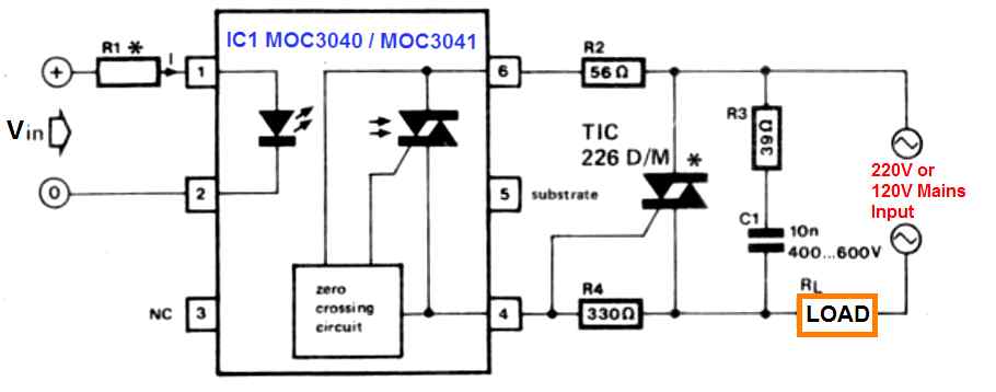
The MOC IC does not have internal snubber, it has external snubber connected parallel to the triac MT1 and MT2 pins. Please refer to the following diagram, the 39 ohm and the 10nF, 400V are the snubber components.
Dear
i am looking for Triac (BT131-600v) control circuit with direct MCU with non isolated & capacitive reactance method, my inductive load is < 5w & output voltage of power supply is +5v dc. Kindly see attached file & guide atleast for correction.
Hi, my Arduino knowledge is not good, so solving your request can be difficult for me. Also, the link you sent is not opening.
ok
HI .I have Triac operated ( max load < 2w ) ckt & my load is connect in series with Line Nutural of MT1 terminal & MT2 terminal in direct connect with phase & gate is drive from MOC3021 &its works well. Now problem is that without connect load no current pass from gate to MT1. Now i need little bit change inside that is whiteout connect load may i see that Triac is operate or not ? I mean my i give direct Line Nutural to MT1 & give load in series with MT2 ? i want to see on board that triac is work or not? what extra very low consumption load i will place inside ?
Hi, you can connect the load with the MT2 terminal, and connect MT1 directly with the common ground, this will allow the triac to work regardless whether the load is connected or not. For the triac to switch ON, the gate current must flow to the ground via the MT1 terminal, otherwise the triac will not conduct.
as per your suggest if i do not connect load then voltmeter shows ac 220v across load? and what about series resistor from phase to MOC transistor ? i mean i connect 1k series resistor from phase to moc pin 6 ?
Yes that’s correct. However, as per the datasheet if an MOC opto coupler is used then the load should be connected to the MT1 side of the external triac. I am not sure how the circuit will behave if the load is connected to the MT2 pin of the triac. The series resistor must be as per the datasheet diagram.
Please check the last circuit on this pdf datasheet
https://www.farnell.com/datasheets/97984.pdf
hi… very helpful article
so, i tried to build electronic controller using arduino + some relay and electronic circuit for my washing machine
currently, i can say, it almost working perfectly , specially for the washing process, it can turn clock wise and counter clock wise, also i can control the speed
what i did is, i control speed using PWM,
the only problem, i’ve found the motor often produce a weird sound
i though it because i dont implement zero cross
another problem, i believe the original circuit (from the manufacturer) dont use pwm to control the speed, so i think it control the triac like using variable resistor but, controlled electronically
i’ve tried to figure out how it will looks like
can we use transistor to control current as replacement of variable resistor?
Hi, thanks for your question. Glad you liked the post.
If you are using PWM with a triac then yes it might have problems due to incorrect zero switching timing.
A MOSFET or a BJT can be used to control the motor with PWM, that is definitely feasible without the zero crossing issue.
using BJT it means using DC
currently the motor using AC,
from googling , since it is a universal motor, it can work well with DC
thank you for the answer
AC motor can be also used by appropriately configuring a bridge rectifier circuit for the BJT. You can see the following example PWM design in which an AC bulb is controlled through a PWM circuit:
Sorry that is not a correct example because the load is getting DC, the AC load must be connected in series with the AC line of the bridge rectifier.
sir
i want to drive Triac BT131 600 with mcu without MOC 3021 & capacitive reactance . kindly check my schematics & guide me it is ok ? gate resistance value proper? suppose mcu pin source 20 ma current then how can i count gate current .give me idea by maths .
Nitesh, I don’t think your circuit is correct.

According to me the following configuration is better and might work correctly…however a capacitive transformerless power supply is NEVER recommended for Arduinos or MCUs:
Dear
i change my thought & now fix it for isolated type so i add MOC 3021 & NTC with 1w zener ,kindly request for check & now it ok ?
what happened if we replace 1000 mfd by 470mfd/25v bcz i have my old one ckt in which i run it with only 100mfd/16v with same mcu & same type load connect with negative side. & it work ok with bride ,, Due to size concern i revised same project so 1000/35 is little big in diameter for me & less adjust on kit
Looks ok to me, but the MOC IC must be configured as per the datasheet diagram:
https://www.farnell.com/datasheets/97984.pdf
470uF is also work.
dear sir
my load is Liquid Vaporizer 3W – 6W Indoor mosquito repellent ( heater coil) , now finely inform me may i connect this heater coil ( as load ) in series with phase & BT MT2 TERMINAL OR or in series with nutural & mt1 terminal side. which one better for long ckt life & less stress on trial .And also explain why ?
i will fix either moc type or whiteout moc bcz it going under thought for price.
mu ic has IOH = -18 ma @5v & IOL = 20ma @ 5v
Nitesh, for standard configurations without MOC IC, you an put the load in series with the MT2 pin, but if MOC is used then please do it as per the datasheet diagram.
Thanks
check this last one & say does it ok ? 5v1 zener 1/2 w not sufficient ? bcz my mood is to sell ckt too cheap & i am fear now days by clone also. so say zener 1/2 w work or heat?
also pl inform may i choose 5D 5 ntc instead of 5d11 bcz it has 4amp steady current while my ckt operate with very few miliamp .so 5D5 has 1amp current .so it work ?
You did not connect the VSS to the other AC line?
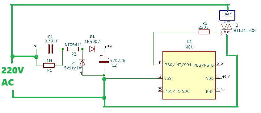
It should be like this:
Dear
it already connected but due to schematics drawling i give lable & it name is N . so it not shown But anyway thanks for guide.
may i choose finally 1/2 w zener & NTC 5dD5?
request for give answer for finial this two part. so my project will move ahead.
OK, no problem, but do not use 1/2 watt zener, use 1 watt or higher rated zener diode for better safety.
NTC can be 5dD5, that is ok…
Dear sir
Thanks for attend.
so i finalized 1w Zener & 5D5. i make both type moc & without & give 2 different price to market .
second after lot of depth think again for moc less circuit ,, when ac & BT off while negative voltage at end of MT2 at that time does my mcu pin get damage or not due to high spike pass from MT2 to gate to MCU pin ? so may i connect 4007 diode in series from mcu pin to resistor & resistor to gate ? so after this last answer i will give design for make pcb sir.
Nitesh, It is not recommended to use a capacitive mains power supply with any sensitive electronic circuits like MCU. But technically your circuit will mostly not cause any harm to the circuit, since one of the phases is protected by series 0.39uF capacitor, and NTC. Also the zener diode ensures the MCU does not get any initial surge current.
If you are worried about the triac gate connection with the MCU output, you can put an LED + 4.7k resistor in series with the triac gate and MCU output, also put a 10k between the triac gate and the ground line (MT1).
Dear
ok thanks.
i will add led +4.7k &10k between gate to mt1
Noted
Thanks
Your first complete circuit has a 1k resistor (R1) in series with a forward biased diode (D1) and a 10v Zener diode (D2). This means there is around 110v effectively across the 1K resistor (R1). That means there is 110 / 1K = 110ma going through the resistor. .110 * 110 = 12.1watts (I * E = P) being dissipated across that resistor; but you’re using a 5 watt resistor. R1 needs to be a much higher resistance.
Thank you for notifying the error, we can increase its value to 4.7k or 10k 5 watt..
You could and should bring the resistance up over 100K. There is no purpose of having such high currents in the triggering circuit; that’s a main point of using a Triac in the first place, to have a small current controlling a larger current. Resistor could be 1/4 watt.
The current should be sufficient to fulfil the triac minimum gate triggering requirements, so the resistor must be calculated according to that.
https://www.homemade-circuits.com/scr-and-triac-gate-resistor-calculator/
That’s correct, but you’re using a BT136, which has a trigger current of only 10ma
Yes, so maybe 30k or 33k is a good value, 100k is too large.
All these diagrams were probably taken from old magazines, therefore they may have some component value errors.
For this particular circuit 100K may be too large, but change some components around and it can work, particularly if you’re using a diac or other thyristor to control the circuit. 100K in the trigger circuit cannot sustain 10ma, however, it doesn’t need to sustain it; it just needs a spike. In my experience, when a thyristor opens, there is a good amount of inrush current that should be enough to kick the triac on. I don’t do much analog design, especially power supply circuits. I needed such a design for a project I am doing and thought maybe I’d find something on the web to save me time. I think it would be silly for a circuit that pisses away 5 watts of power, even when the switch is off.
If you have a capacitor before the diac then things can change drastically, then even a 100k or even higher value works, especially when the trigger is not continuous rather very sharp and for a very short duration of time.
Well that’s exactly what I mean. When the thyristor’s trigger voltage is reached, the cap will dump its stored energy through it to kick the triac on. The triac, once triggered will stay on for the remainder of the waves half cycle; that’s the way a triac is typically used for current limiting from a 120/240vac source. This allows for efficient energy usage.
The trigger voltage of an SCR/Triac can be as low as 0.6V, so the capacitor trick won’t work, it might work only if a diac is used whose firing voltage is around 30V.
So high value resistor like 100k will not work if the load is supposed to be switched ON continuously by the triac at full power.