A very simple touch free faucet circuit or touch free automatic tap circuit can be built using as little as an IC 555 and a few passive components, in order to implement a contact less water supply operation from the attached facet or the tap.
Drinking Water is Precious
Pure drinking water which we normally get in our cities and homes is precious, and we are always advised to conserve drinking water as much as possible by saving unnecessary wastage of water due to carelessness or negligence.
Especially in public places this issue can become quite grim as many irresponsible citizens often forget to close a water tap or partially close it allowing unnecessary wastage of water.
An automatic tap system that would take care of the above condition could be a welcome change in many such places for ensuring the prevention of unnecessary throwing away of our precious drinking water into drainages.

Designing an Automatic Water Cut-off
You may also like this very interesting article related to this subject
We have already seen how the IC 555 can be used as an effective capacitive switch circuit wherein this device is able to sense a nearing human hand and activate its output accordingly. In the present concept we try the same concept to build the proposed touch free faucet circuit.
For higher accuracy and reliability you could also try implementing a specialized precision capacitive proximity sensor circuit for the same, although the installation procedures would remain the same.
The first circuit below shows a 555 IC application, which could be tried for the implementing a non-contact tap faucet design:
Circuit Diagram
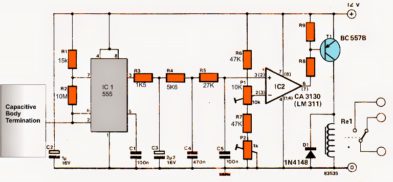
image courtesy: elektor electronics
As can be seen in the figure above, the IC 555 is configured as an astable whose pin#2 is used for sensing the proximity or the capacitance of a human hand.
Pin#2 is terminated with a metallic plate (which could be replaced by the faucet body) such that whenever somebody approaches the tap for washing hands, the sensor is triggered activating the connected relay. The relay finally opens the tap valve for releasing water.
However in the above design the relay is supposed to remain activated only for a short duration of time, which means the individual might require to move his hand to and fro frequently if the washing is required to be for a relatively prolonged period.
Another design which is shown below can be executed for the same:
A Improved Faucet Control Schematic
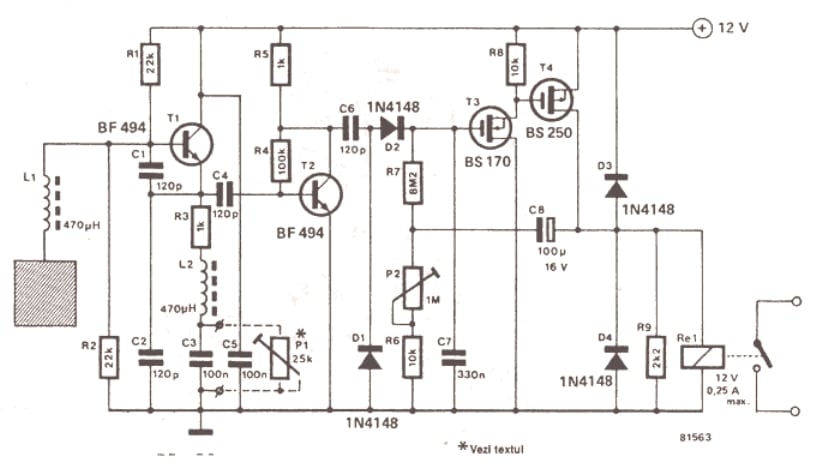
image courtesy: elektor electronics
The above shown proximity detector circuit is a transistor based design and is designed to sense a human hand when brought at a relatively close proximity to the indicated plate.
Circuit Operation
The T1, and T2 transistors are rigged quite in the manner like a Darlington pairs forming a high gain detector stage.
The capacitive plate attached with the base of T1 sense the minute potential differences due to the variations in the capacitance of the plate in response to the human hand and conducts some current at its emitter lead, which is picked by T2 and amplified to a greater extent across its collector lead.
This preamplified signal is detected by the FET stages, which further amplify it to a level strong enough to cause the relay to toggle.
Since the proposed touch free faucet design is an electrically activated device, the water control mechanism needs to be implemented through a water valve mechanism, such as a 12V solenoid valve system.
A typical 12V solenoid valve system can be witnessed below:
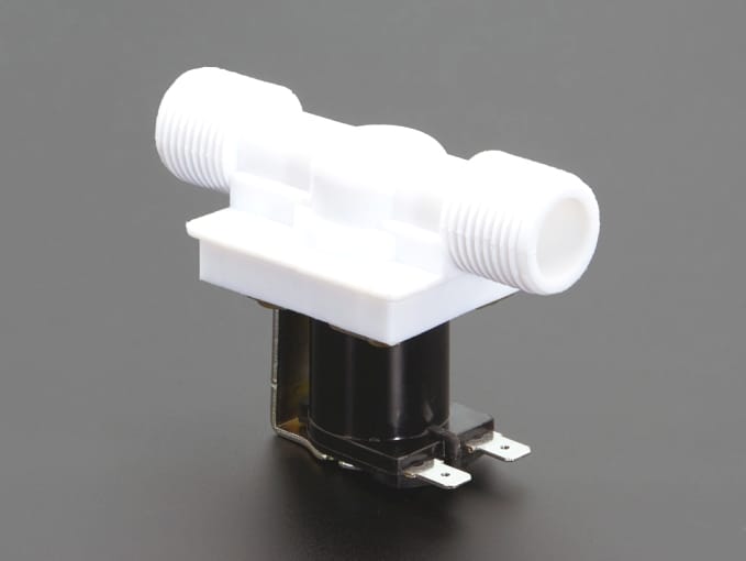
Integrating a 12V Solenoid
The two leads are supposed to be fed with a switchable 12V supply in order to close and open the water passage through the white plastic pipe. The white plastic pipe needs to be inserted in series with the faucet water transmission line so that the water supply from the faucet is appropriately controlled via the above discussed operations.
The basic connection details of the above mechanism in conjunction with the electronic circuit and the faucet can be seen below, the user can feel free customize the same in other ways as per his or her preference.
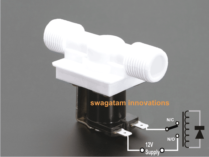
Note: If the faucet body does not respond to the hand proximity, the system could be reinforced with a small additional metal plate in order to increase the surface area of the capacitive sensor and thereby ensure a reliable operation of the touch free faucet.


Comments (30)
I ordered a touch faucet online, and it works great. Now I want to make it Alexa-compatible in the simplest way possible. I can get an Alexa-compatible smart relay with Common, NC, and NO terminals. I want to change the faucet circuit as little as possible. If there were a way to simulate touching the faucet, that would be great. There is a wire from the controller that attaches to the faucet that detects touch. What’s your thoughts on using the smart relay to simulate touching the faucet?
It sounds great, must be tried!
Good day Sir,
Are the circuits above sunproof?
I’m learning so much from your blog thanks alot
hank you Evangel, these circuits are capacitive based circuit so it cannot get affected by the sun light, so yes these are sun proof
Delay off time,
Hello sir,
I am working on automatic hand sanitizer machine. In that i have used IR sensor tx, rx. Currently it works fine when sensor is sensed pump is on till that time. Now In that i want to OFF the the pump after 1-2sec even if sensor is sensed. So please give the solution.
Chintan, if you have use a transistor as the output amplifier, you can connect the PIR output to the transistor base through 1N4148 diode, and then connect a 10uF/25V capacitor across cathode of the diode and circuit ground line. The cathode will be toward the transistor base and the anode towards the PIR out pin.
Can I have a diagram please
Dear Swagatam Sir,
Please provide us circuit for automatic faucet.
thanks & regards
Dear Rajkumar, I am sorry I can’t help you with PCB design due to work pressure! You may have to contact a professional online designer for this.
Are you able to show the making of an automated faucet via a video clip?
Ok..it may result from DC..you are right…thanks again for your kindness and interest
Is there anybody who makes this circuit work/run?
I built the circuit on breadboard but it didn't work.Let me tell you what I did:
1. 8.and 9.resistors are 47K..right?
2. I used LM311..right?
3. I connected other parts true..
As soon as I connect 12V to circuit the relay run/work.Relay musn't work normally, it must run when I approach the capasitive body termination.Where is the problem?
Mustafa, the circuit was tested by the elektor electronics engineer, and this has taken from the same magazine, so it has to work.
also it was tested by Mr.Bugoy one of the dedicated readers of this blog, you can read the discussions below:
https://www.homemade-circuits.com/2014/05/capacitive-switch-circuit-for-vehicle.html
However the circuit worked only when used with a battery but when use with a AC/DC power supply it somehow did not work correctly
may be you can check it with a battery and see whether it responds or not….
Dear Sir,
I used only 555 stage disconnecting second stage and connecting a led which is parallel to C3. However it didn't run as you said!?
Thanks a lot
test the stages separately….initially keep the opamp stage isolated from the 555 stage by disconnecting it from R5/C5 junction….connect an LED in parallel to C3 and check its response when you bring your hand close to the capacitive plate, this will confirm the 555 working….after this you can proceed with the opamp stage separately
thank you sir
where. can i buy this capacitive touch plate..what is its cost in india..in online i saw some capacitive touch plate with 3 pin out.in your diagram there is only 1 pinout for plate..help me pls
the touch plate does not need to be purchased, it can be done by using any small suitable metal plate, or handmade by cutting a tin or aluminum with scissors.
thank you sir for help
in circuit i saw capacitors like 470n 100n..what is that all.is it available in india..tell me substitutes for those components
i think i have to connect pin 2 to tap body..can you tell me the pin out for ic 2 lm311
NVD
470nF is equal to 0.47uF, and 100nF = 0.1uF you can try other value which are closer to this
First confirm the circuit on your work table by using a small plate as the sensor, if it works correctly then you can proceed with the tap connection.
sir
in case of my pir module..when we show our hand relay will open..it delays about 5s..is there any way to reduce the delay otherwise water will get wasted..if you want i can send picture of my pir..how to upload picture
NVD, if the delay is happening from the PIR module itself then there's no way to correct since that would mean modifying the internal SMD circuit which can harm the module.
Nived, You can combine the following concept with your PIR, that will work better:
https://www.homemade-circuits.com/2012/05/simple-delay-timer-circuits-explained.html
or simply you can modify the existing PIR circuit as explained in the above delay timer article
Swagatam
I think the connections to the solenoid valve shown in the last picture is not correct.
Thank you Abu-Hafss, I have corrected it now…
Can i connect PIR sensor to this CIRCUIT that PIR faces towords the tap that sence hand only
WAS this suitabel . thank you
Minimum time adjustment of PIR sensor can be long for the faucet So much water consumption can be problem
PIR can be used and with that you can use a simple transistor relay driver circuit, the above IC based circuit is not required