The IC 4017 is a versatile counter divider IC which can be applied for making many different interesting electronic circuits. In this post I have explained about a few useful yet simple 4017 IC circuits and projects, assorted and compiled from this blog.
How to Understand IC 4017 Pinouts
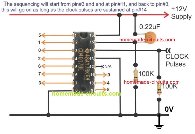
Before we delve into the many circuits built using the IC 4017, it would be very important to first learn how the various pinouts of the IC are designed to work. This chapter explains in details regarding how to configure the pinouts of the IC 4017.
Sequential LED Array Light Circuit Using IC 4017 Explained
Are you interested to build a sequential mains controlled running lamp circuit? For users who want to build a device which will allow 10 mains AC operated lamps to light in a sequential manner, creating running lamp effect, this simple 4017 project can be the one you are looking for.
Electronic Dice Circuit [Digital Dice]
We all have played some or the other way, with this thing called the dice, which has a cube like structure with 1 to 6 dots printed on each of its 6 surfaces. In this specific article I have explained how to build the electronic version of the dice, which would produce the same results as our old manual dice, but in the digital format.
3-Digit LED Capacitance Meter Circuit
Capacitance meter is a very useful device which can be used for measuring the values of unknown capacitors. This feature is mostly not available in regular digital multimeters. But this can be easily built using the IC 4017 through a simple circuit as discussed in the following article.
Converting Wasted Spark Ignition to Sequential Spark, for High Efficiency Combustion
As the name suggests this 4017 based circuit has something to do with the saving fuel in vehicles. That's right, the above customized simple 4017 circuit is configured in such a way that its sequential output can be used for converting the unused sparks in a car engine into useful combustion, thereby improving the fuel consumption of the vehicle and the overall efficiency of the vehicle. More can be read in this article.
Touch Dimmable LED Light Bar Circuit
The IC 4017 can be also used for making a touch operated LED lamp, which will simply respond to your fingers for switching ON and Off. You can learn more about this simple IC 4017 based touch activated LED lamp project in the following post.

Rotating LED Chakra Circuit for God Idols
A rotating LED lamp can be a great way of decorating any specific item, mostly the ones that are related to gods, such as a god idol. Just imagine, some bright colorful LEDs moving in circles at the back of the head of a God idol, this can create an awesome looking decoration item, and can be a great piece of attraction at home. In the following post I have explained how to build one such simple 4017 circuit projects.
4 Simple Clap Switch Circuits [Tested]
A clap switch is a device that operates a load ON/OFF in response to clap sounds. An ordinary IC 4017 circuit is quite sufficient for configuring a great sound operated relay switch which will switch ON and switch OFF any load connected to the output relay. One such project is explained in the following article:
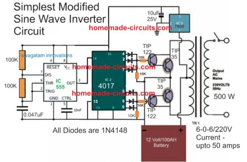
7 Modified Sine Wave Inverter Circuits Explored – 100W to 3kVA
A sine wave inverter is always considered to be a complex project since it allows the generation of the output AC with a pure sine waveform. However, you can easily construct a an almost pure sine wave like 220V inverter using a single IC 4017 and a few other components, as explained in the following article:
LED Chaser Circuits – Knight Rider, Scanner, Reverse-Forward, Cascaded
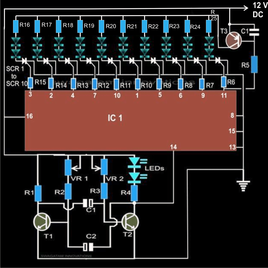
It seems we missed this one of the most popular applications of the IC 4017. The application is about LED chaser circuit which works specifically by suing this Johnson's counter divide by 10 IC 4017. A number of different chser circuit are covered under this post, which includes, the famous knight rider chaser, LED scanner circuit, 16 LED cascaded chaser and many more.
There are plenty of more simple 4017 IC circuit projects that you can build, and exploit the huge application range of this extremely useful IC.
Miscellaneous 4017 Circuit
This is a circuit for a 10-stage sequential LED flasher or chaser, in which a single LED is switched on at any one instant and the other nine are off, with the on LED advancing one step up in response to each input clock pulse.
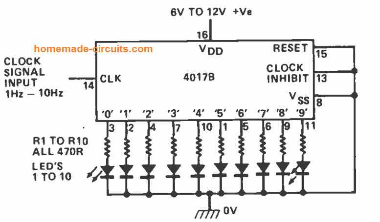
Reversing the polarity of all LEDs and connecting their common point to the positive supply line produces an alternate action in which nine LEDs are on and one is off at any one instant, and advances in response to the clock pulses at pin#14.
Musical Tone Generator
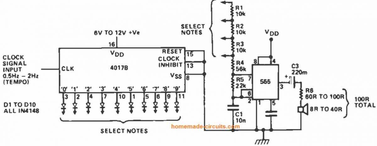
A desired musical tune or melody may be generated with this circuit of a 10-stage 4-note musical sequencer. Several more resistors can be added to the R1-R4 network chain to maximize the number of accessible notes.
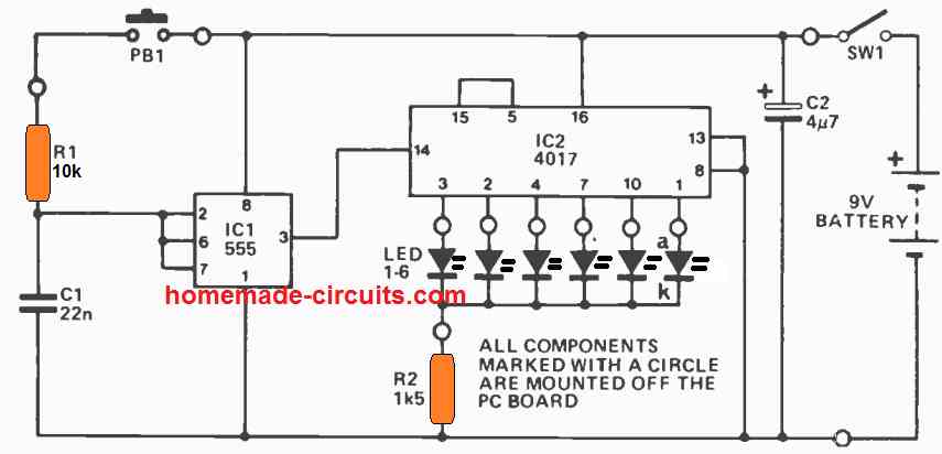
How to Create a Single Output Sequence and then Stop
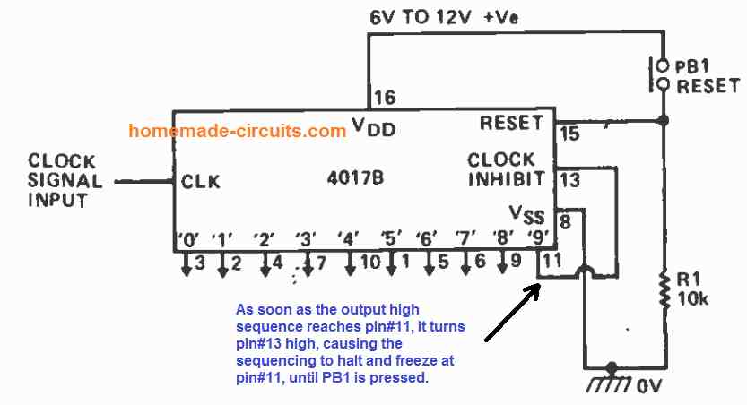
The above 4017 circuit demonstrates a simple way to wire the 4017 such the counting freezes after a preset counting sequence. The counter is configured to halt as soon as the "9" output drives the clock inhibit pin#13 high. By pushing the reset switch PB1, the counting sequence could be reinitialized. This also means that, by connecting any other desired output pin with pin#13., the sequencing could be made to halt on that specific output pin.

Questions & Answers
Hello Sir. There is this project am undertaking titled *SEQUENCE KNOCK MAGNETIC LOCK WITH POWER BACKUP*
This involves a door that is magnetically locked. For one to open the door, they must knock for a predefined number of times (sequence) and the lock will demagnetise and hence open. A buzzer should sound to indicate the opening of the door.
The electromagnet should automatically be re-energized so that when the door is shut, it’s locked.
Moreover, the backup should be in place so that incase of a blackout, the door can still be operated.
I need you help Sir. Here is a circuit have designed on the same, but I doubt the automation circuit
https://eu.docworkspace.com/d/sIAnO3PeyAb23_bYG
Jedidiah, I checked your circuit diagram in my email, and looks ok to me:
Make sure to add a 0.22uF capacitor parallel to the reset switch so that when power is first switched ON, the 4017 output automatically resets to its initial pin#3.
Can you please specify what issue regarding automation are you facing in this circuit? I will try to figure it out.
Can two solenoids be used to provide magnetism for the locking mechanism or what options are available Sir?
Can you please provide more details regarding how you want the two solenoids to operate for the automatic locking?
Thank you.
One installed at the door and the other at the door frame. When energised and the door is locked, one produces a magnetic field opposite to the other and hence attraction occurs.
For this operation two solenoids are not required, you can simply use car central lock solenoid for the operation, which can be operated forward and backward alternately, in response to each subsequent DC supply trigger.
Thank you Sir! I have done as recommended. However, a problem has cropped up, whereby, there is false triggering at the 4017 ‘s output. Besides, the relay and the buzzer are in parallel so that when the door is opened, the buzzer sounds. What is unfortunately happening is that they are both actuated but for just a second. The 4017 output cannot be sustained! Remember also that this is happening in spite of putting a 10uF capacitor across the relay switch that switches the car door-lock solenoid. Please help me out.
Thank you.
Thank you Jedidah,
It could be happening due to the spikes from the solenoid coil, and switch debouncing…
Please try the following:
Put a 47 ohm or any other small value resistor in series with the 12V supply that goes to the ICs.
Put a 100uF/25V capacitor and a 0.1uF capacitor after this resistor, across the positive and ground supply lines.
Put a small value capacitor between pin#15 and ground of the 4017 and also between its pin#14 and ground.
I can also see there’s no base resistor used for the BC547, please use a 10k for the BC547 base resistor. You can replace the BC547 with a new one, if you find it is already blown.
Thank you Sir.
1. Is the small value resistor put in series with the 12v supply going to all ICs used or the 4017 alone?
2. Are the 100uF and 0.1uF (after the resistor) put in series or parallel to each other?
…. additionally Sir. When I connect the flywheel diode across the relay, the relay is not energised, unless I disengaged it
… I’ve sent you the circuit please Sir.
Thank you.
Hello Sir. I’ve done it as adviced… unfortunately, the problem has shifted a little bit. The solenoid lock is still not latched when energised. A signal from CD4017 appears for some microseconds and disappears consequently unlocking and locking again. Are there any additional alterations I should do?
Hello Jedidiah,
I did not get any email sent by you in my inbox.
Meanwhile you can try this. Please connect the pin#3 of the 555 with pin#14 of 4017 through a 10k resistor and then connect a 1uF capacitor between pin#14 and ground of the 4017.
The flywheel diode is a must across the relay coil, and it should not cause any issues with the toggling of the relay, you can replacing the diode with a new one and also connect a 10uF capacitor parallel to the relay coil….
Hi Jedidah,
Both the capacitors must be connected across the +12V line and the Ground line, very near to the IC (+) and ground supply pins. This positive line must be fed through a small value resistor.
Otherwise you can replicate this network:
Connect a 0.1uF also parallel to the 100uF
…Also make sure to connect the pin#3 of IC 555 with pin#14 of 4017 through a 1k resistor and then connect a capacitor between pin#14 and ground…
Hello sir. God is Good. Thank youso much… it worked! I found out the problem at the monostable MV. I rewired it and its perfectly OK even with the buzzer engaged!
Thanks for you patience and tolerance.
That’s great Jedidiah, Glad it is solved now. All the best to you….
Hello Sir.
I’ve sent the circuit Sir. hope it was delivered this time round.
Hi Jedidiah,
Yes, I received your email.
I think you must proceed and check the circuit stage wise.
Please disconnect the buzzer, the solenoid and the counter circuit, test only the relay operation.
Also, the resistor from the pin#3 of 555 must be directly connected to the pin#14 of 4017, there should be no other connections between this resistor and pin#14, except the capacitor to ground at pin#14.
The LED, the counter input connections must all be done directly with pin#3 of 555.
Check the relay operation.
If it works then connect the solenoid and test again.
Make sure to connect the freewheeling diode across the relay coil and the solenoid coil.
Thanks Jedidiah,
Your link is telling me to download the wps office which I don’t want, so please if possible send the diagram to my email ID, I will check it out and try to solve it for you:
homemadecircuits
@gmail.com
I have an old Seeburg wall box I need to build a decoder for. The wall box sends out a pulse up to 20 pulses to select a song, what I am looking for is to use 2- 4017 chips to count how many pluses arrived from a relay pulsing in the wall box to advance my 4017 counts. I need a circuit that can take a N.O switch contact and advance the 4017 with each time it closes. My problem has been to get the chip to count correctly without false trips or false advances.
when power is cut to the chip it needs to reset and restart another count total. Getting the 4017 to be accurate has been a real issue. Please help. Thanks.
4017 IC sequencing can be very accurate if its clock input pin#14 is configured correctly with debouncing network.
You can configure the N/O contact of the relay with pin#14 of 4017 in the following manner:
Connect the common pole of the relay with the positive DC (below 15V)
Connect the N/O contact of the relay with pin#14 of the 4017 IC through a 1k resistor.
Connect a 10k resistor between pin#14 and ground.
Connect a capacitor of 0.33uF or 0.47uF between pin#14 and ground.
For the auto reset action, do the following things:
Insert a 10k resistor in series with the existing pin#15 connection of your ICs.
Connect a 0.22uF capacitor between the positive line and the pin#15.
Let me know if you face any issues with the configurations and working…
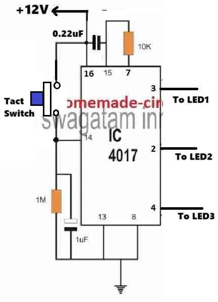
Would you please show me a circuit that uses the 4017 chip switching on up to three leds [one at a time] whenever I press a momentary tact switch? Thanks so much. Len.
Sure, You can try the following design:
I need help in wiring up a 4017 circuit where I use a momentary touch switch to switch on 4 separate latched-on leds and this is repeated only when I touch the momentary switch. In one of the on positions I think that I can figure out how to have two outputs latched on at the same time. So- the tact switch is pressed and #1 led comes on. The tact switch is pressed again and #1 led goes off and #2 led comes on. Tact switch is pressed again and # 2 led goes off and #3 led comes on. Tact switch is pressed again and # 3 led comes on along with # 4 led. Thanks so much for any help that you can give me. Len.
Thank you for your question,
However, the outputs of IC 4017 can produce only one output ON at a time. Having two outputs randomly latched may not be possible with single tact switch.
Let me know your thoughts on this, or if you have any other opinions.
In the touch dimmable led light bar circuit, I noticed that you are using NPN transistors to power the LEds. I am working on a circuit where I want to drive several LEDs with a 4017 and I want the high side driven by the 4017 which can’t drive several LEDs because of current limitations. Therefor I plan on using a similar design to this design. My question is: can I substitute BT169 SCRs for the NPN transistors? This might make the LED circuit more interesting. I know it is standard procedure to drive LEDs from the low side with transistors and with their emitters connected directly to ground. With my limited knowledge I have never quite understood how to use NPN transistors to power circuits, only to ground circuits. Thanks for your time! I would appreciate your input.
Hello Norman, The transistors are configured as emitter followers which can replicate their base voltages at their emitter loads.
The bases of the BJTs are configured with decreasing voltage levels through resistive divider network, which ensures a decreasing voltage for the LEDs as the 4017 output moves sequentially causing the required dimming effect on the LEDs.
These BJTs cannot be replaced with SCRs, the dimming effect would not work then.
I have been exploring options and feel this chip holds the solution to my issue. I have a momentary output of 12VDC(+) that I need to cycle through 3 outputs to have a (-) constant until the next (+) pulse. 1st (+) pulse = a (-) constant on output 1 until the next (+) pulse which deactivates output 1 and activates output 2 (-) constant until the next (+) input which deactivates output 2 and activates output 3 (-) constant. The next pulse would need to turn output three off and remain in that state. The next (+) pulse would then start the cycle over. Any assistance would be greatly appreciated.
Yes, the above IC can be configured for your specific application. However, the 4017 IC normally will produce (+) outputs sequentially. It will not produce (-) outputs.
It may be possible to convert the (+) outputs into 0V outputs if required, through NPN transistors stages connected across each output of the IC.