The digital time clock explained here is a circuit which most electronic amateurs would love to make.
You might have heard about digital clocks made from clock ICs such as the popular LM8361, MM5387 etc but these ICs could be today quite obsolete and/or complex to build.
Circuit Operation
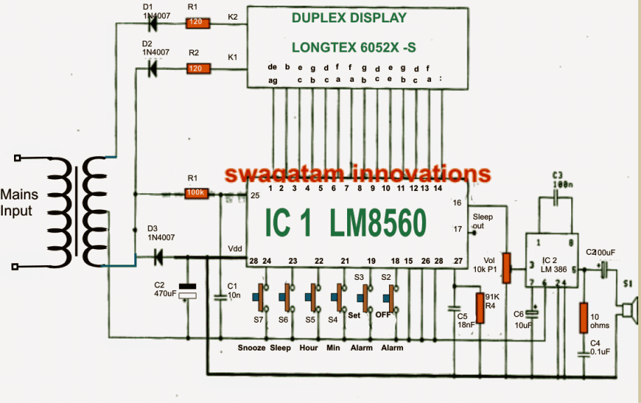
The present design is much easier and no less than their above mentioned counterparts in terms of feature and specs. Moreover there's one added advantage included in this digital clock circuit, it's Duplex LED display model, which helps to reduce the number of connections and links across the IC1 (LM8560) and the LED display, allowing the configuration to be much simpler.
Now I have explained how the proposed digital clock circuit functions:
As may be witnessed in the given diagram the heart of the circuit is formed by the IC1 (LM8560),
which is assigned with the following outputs terminals:
1. The output for driving the display Duplex Model numbers (pin 1-14)
2. The output for generating an alarm signal at pin 16.
3. The output option which may be utilized for controlling external electrical appliances through an in-built automatic timer.
The parts R1, C1 are included in the circuit in order to facilitate an input 50 Hz clock to pin25 of the IC.
The diodes D1, D2 are positioned as rectifiers to function as signal generators to the cathode of display number for generating an alternating working of the display illumination in relation with the input of IC1.
The alarm signal from pin 16 of IC1, is hooked up with a potentiometer P1(Volume) and further integrated with pin 3 of IC2 (LM386) which forms the amplifier stage for driving a loudspeaker during alarm activations.
The P1 is included in order to provide a fine tuning option for the alarm signal volume. Additionally the signal from the "sleep" pinout from pin 17 may be used for controlling any other desired trigger circuit.
How to set the time in this digital clock
1. S6 is used to set hours.
2. S4 is used to set minutes.
To set the alarm time the following switches may be used:
1. S3 to hold down the time
2. S5 to set hours for the alarm.
3. S4 to set minutes for the alarmm.
Once the above mentioned time limit through S4/S5 elapses, the alarm may start ringing which may be stopped by pressing switch S2 or in fact any other switch out of the given ones.
The following switches may be used for controlling an external appliance from the clock triggers.
1. Initially you would need to keep switch S6 pressed
2. Next press S4 to set minutes.
3. Press switch S5 to set hours.
The output signal for the above explained ON/OFF control of appliances may be acquired from pin17 of the IC.
Using time dilation alarm to repeat alarm.
In order to use this function if in case we want to Repeat alarm or to extended for another nine minutes, you may want to press switch S7.
Circuit Diagram


Questions & Answers
Sir, I have a stupid question… can we safely connect two smps (exactly same) output in parallel to get more Amps. Extra safely diode should not net be needed as smps already included that one to convert 12v ac to dc. Google search says its dangerous and will create trouble soon or later. Both smps power supply board also include led so can we easily got to know if any one runout.
s2.postimg.org/u325x30xl/2015_02_26_00_10_27.jpg
Ram, you can connect bridge networks at the outputs of each of the SMPS and join the outputs from the bridge networks in parallel then I think there cannot be any chance of any issue, and both the SMPS will run smoothly.
Sir, does the LM8560 could drive a big seven segment such as 5 inch ? Or do I need a driver ? I want to make a big digital clock . . .
Thank's . . .
Vicky, I don't know about the ICs output current sinking capacity, you can connect it without a driver initially, if it does not glow brightly then you can opt for a driver stage.
sir,
how to connect single digit displays as duplex mode.
thanks
narsingrao
hyderabad
compare their pin details from the respective datasheets and connect accordingly
can someone tell me where can i get the duplex display pls?
Hello Swagatam,
Thank you for sharing the design for digital clock using LM8560.
Out of curiosity, i would like to understand if it is possible to program/configure this or some other IC in such a manner that it repetitively alarms say after every x hours.
Suppose i want it to run for 3 hours then snooze for next 6 hrs, then run for next 3, again snooze for next 5, run for next 3 and then again snooze for next 4 – repetitively?
Awaiting your response, thanks in advance 🙂
Hello Puneet, no I don't think the above circuit can be configured for the mentioned function, however you can use the following external timer for achieving the results, but how it could be integrated for the triggering with the above clock is a matter of some investigation:
https://www.homemade-circuits.com/2012/04/how-to-make-simple-programmable-timer.html
Mr. Swagatam,
Kindely asking if you can help me about my diploma thesis project!?. I need specific literacy about creating a "Digital Clock Circuit Design Using 7493". Thank you in advance.
Bekim, I think it is already present in one of the online sites….please Google it to find it
Swagatam, you are a Ggeat Man. I really love you and your Work. Keep it up, God bless you.
It's my pleasure Joseph, God bless you too!!
Hi Swagatam,
I have a digital clock bought it from an old electronic selling shop.It has main IC TMS3450NL (same as LM8560).Its working fine but the problem is 4 to 5 mins advance than standard time.I already changed its 2 caps one is poly and other is non poly myler cap. But same prob still there.Here in my area there is no TMS3450NL timer ic in the market but LM8560 easily available.Do u think its IC fault or other fault. Kindly suggest me whats the culprit be there.
Hi Naeem,
I don’t think the IC has any external frequency setting components, the internal oscillator seems to be synchronized with your AC mains 50Hz cycle, at pin#26. So changing the external capacitors may not help, you may have to check whether pin#26 is correctly getting the AC mains frequency or not, or you can try replacing it with a new IC.
Hi Swagatam,
Thankx for ur reply, one more thing i want to khow this digital clock is in 24hr format display mode, i want to set it in 12 hr format. I open its pin 28 from supply, it turned in 12 hr format but its 12 hr digits not properly displayed on. By the way this device circuit is little bit differ from the circuit here published by u.So how can i set it in 12 hr format properly
Thankx
Naeem
Thanks Naeem, I have not yet checked the above circuit practically, so it can be difficult for me to suggest anything with confirmation.
HI Swagatam,
Pls Suggest me an inverter circuit with following features
dc source lithium ion 3.7 to 4v
output ac power 100w-200w
charger Li-ion
Thnkx
Naeem
Hi Naeem,
you can try the first circuit for the purpose
https://www.homemade-circuits.com/mini-50-watt-mosfet-inverter-circuit/
just make sure to use a 3-0-3V/220V/15 amp transformer and a 3.7V 25 Ah battery
thanks for your good work. God bless
how to work RF circuit
LC circuit and send and Reception connect
In above circuit, which transformer is used, and what is the ratio of the transformer?
is it okay if i use 12 volt ac adapter, if so then where should i connect the ac source?
Please use a transformer only as shown in the diagram, the transformer can be a 6-0-6V /1 amp transformer
Seen digital led clock. It’s good.
Is it possible to buy it’s kit or PCB?
What is the price
Thank you, however sorry we don’t sell parts or kits in this website!
Hello Swagatam. Please can this circuit digram be used for normal 7 segment display?
I can’t get duplex display that’s why.
Hi Joseph, I do not have much idea about it, I think you will have to compare the pinout details of the duplex module and the single 7 segment module, if their specifications match then probabaly you can configure the individual blocks with the circuit accordingly.
Dear Majumdar,
I am very happy to see your efforts in sharing the knowledge with the others. This is a Good indication for the development of our society.
I have a doubt on the following points.
If we are using high end 9.2 AV receivers like Pioneer or Onkyo, and we want to add Pre- amplifier and Graphic Equalizer, the sequence of connections
(A) – (1) Input to Graphic Equalizer, (2) Equalizer output to Pre-amplifier input and (3) Pre-amplifier output to Av Receiver input.
(B) – (1) Input to Pre-amplifier, (2) Pre-amplifier output to Graphic Equalizer input and (3) Graphic Equalizer output to AV-Receiver input.
Please suggest to me, whether above (A) is better or (B) is better.
Thank you Brahmaiah, As you can see the above post is regarding digital clock, and not related to amplifier and equalizer. So please post your question under an amplifier or equalizer article, I’ll try to answer it quickly
Can you explain wiring diagram of seven segments?
Please see the datasheet of the IC
http://www.paulanders.com/G5-LED/ver1/datablad.pdf
Thanks for sharing your knowledge. Although I am an electrical engineer I have spent my career in the 120V-600V world and do not remember much about the <12V dc world. I am trying to build a basic clock and do not care about alarms, snooze, etc. Just a 12 hour (as opposed to 24 hour) clock.
Is this chip (the LM8560) overkill for my application? I am looking for low cost (I need to integrate a clock circuit into another product) and need a chip that will be around for a while.
Does this chip require any programming (as does the AT89C2051 that seems to be popular)?
Second, I need a simple stopwatch timer as well. Press "start" and the counter begins to count. (Would obviously need a STOP and RESET function, LAP function not important. Could this chip be used for such a task, or is that something else? Thanks!
Thanks for your question, yes you can use this circuit for your basic clock operations, but the stop watch facility may not be available with this circuit.
This chip is not programmable, and it comes preprogrammed, so programming is not required from the user.
For the stop watch you may have employ an additional circuit such as this one:
https://www.homemade-circuits.com/?s=stop+watch+
Hi Swag,
Are the diodes in this circuit correct?
Shouldn’t they be facing forward?
And the display: It’s has to be that reference or can I use ordinary 7 segment displays?
Best Regards.
Nélio.
Hi Nelio, the diodes are correctly shown…the center tap of the transformer functions as the positive line.
I am not sure if ordinary 7 segment would work here, but I think it is worth trying by matching the respective pinouts.
Hi Swag,
There are 2 pins 28?
Is this correct?
Nélio
Hi Nelio, yes you are correct!
So pin 28 connects both to the anode of the diode and to the center tap of the transformer.
Nélio Abreu
Hi Swag,
I notice that pin 20 is missing.
No connection?
Nélio Abreu
Hi Nelio, Thanks for pointing out the mistake. Please see the Vdd pin of the IC. the Vdd pin is mistakenly shown as pin#28, which should be actually pin#20.
Hi,
You are welcome.
Keep up the good projects.
Best Regards.
Nélio
How many hours data can be stored and how many days after will reset?
Dear sir what is the transformer secondary voltage, kindly tell me the working voltage of this circuit. thank you
Hi Ashok, you can use a 6-0-6V 500 mA transformer. The max working voltage of the circuit is 15V
Dear sir, Where is get from this IC ?
I want some ICs
Please check online you may find some sources.
Can you suggest best online shop?
All online shops are good. I cannot suggest a particular shop.
Respected Sir,
Since we have frequent AC power outages, kindly advise how can we change this circuit and add a battery back up (not for display) so as to when AC power returns, the clock time doesnt resets. Thanks.
Hi Fouzan,
You can connect a small lead acid battery right across the capacitor C2. Just make sure to add a 100 ohm 1/2 watt resistor in series the positive of the battery.
Thanks for the advice Sir. What should be the voltage of Lead Acid battery ? Would it create battery overcharging issue ?
Fouzan, If the transformer is 6-0-6V, then the battery can e also a 6V battery 4 Ah.
Due to the series 100 ohm resistor, the battery will safe from over charging.
Thanks Sir, I shall try and share the results.
No problem Fouzan, all the best to you!
Hey sir can you guide me how can we make this digital allram clock without the IC1 (LM8560) which you used as a heart of your circuit is there anny other way to design your circuit
Hi Rashmeet,
If you want an alternative version then you can refer to this page:
https://www.homemade-circuits.com/?s=digital+clock
or maybe tis page:
https://www.academia.edu/40145966/ELECTRONIC_DIGITAL_CLOCK
hi sir thanks for your quick response. sir my academy wants me to make digital ic based alram clock my concern is the way you made your circuit with IC1 (LM8560) you made your project very smoth and the IC works as all in one so my question is can we make a digital clock with the help of basic componets like
• 555 timer IC
• Common-cathode 7-segment display
• counter IC
• regulator IC
• Resistors
• Capacitors
• Diodes
• 12V Transformer
and then can we add a alram feature to it
Rashmeet, you can try the following circuit, and let me know how it goes:
https://www.homemade-circuits.com/wp-content/uploads/2024/09/ELECTRONIC_DIGITAL_CLOCK.pdf
respected sir appreciate for your responce actually i understand the given circuit (https://www.homemade-circuits.com/wp-content/uploads/2024/09/ELECTRONIC_DIGITAL_CLOCK.pdf) but im looking to add alarm feature to it it will be really help full if you will tell how i can add that feature to it via circuit diagram
thanks in advance
Rashmeet, Can you please tell me what type of alarm are you looking for, is it the hourly alarm that must sound every hour?
hey sir im looking to add a DIP type alarm so that I can set the alarm time and make it snooz or off with a switch it will be really help full if you help me with schamtic of (https://www.homemade-circuits.com/wp-content/uploads/2024/09/ELECTRONIC_DIGITAL_CLOCK.pdf) with an alarm switch
thanks
Rashmeet, I may try to design it but the alarm time selection would be limited to hours only, not through minutes or seconds.
Let me know if that’s ok with you…
Hi sir that will be helpful in all ways to me all though my instructor wants me to have fully functional alarm with minutes and second it will be really helpful if you will guide me with this too. do we have to use my other type of alarm instead to DIP TO MAKE it fully functionalable ?
Hi Rashmeet,
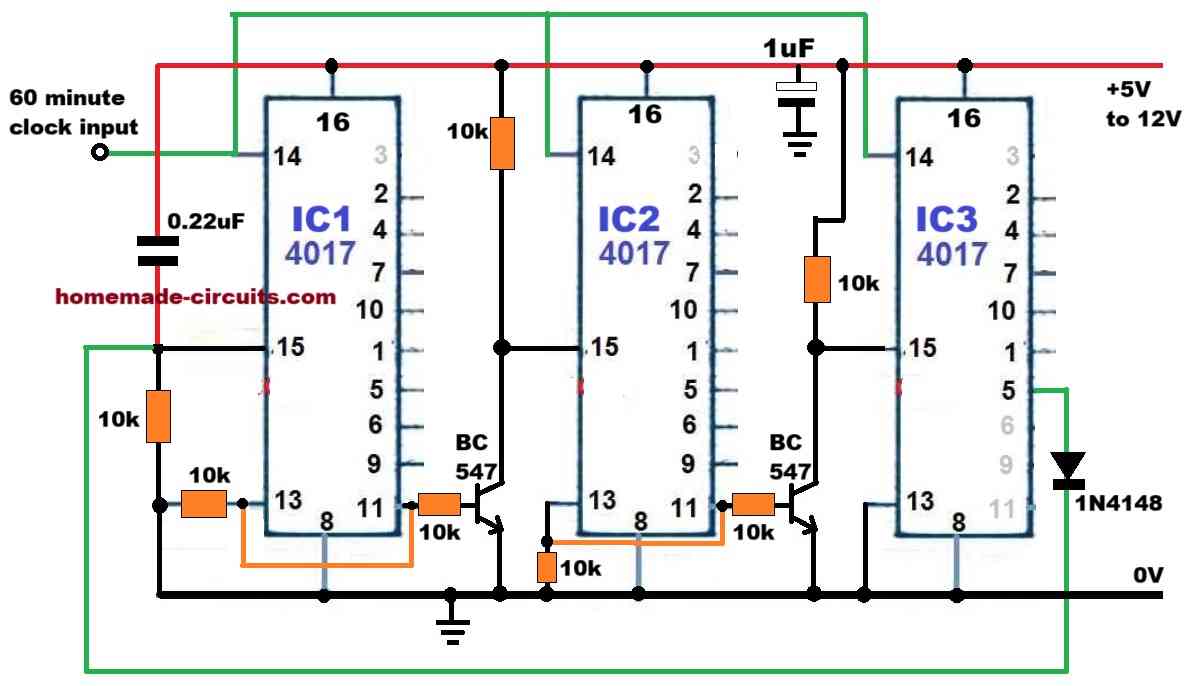
Please try the following 24V hour counter circuit, and test it with your clock circuit, if everything goes correctly, then afterwards I will you the alarm driver and snooze stage of the circuit.
Where can i get the digital clock PCB
Sorry, I do not have the PCB for this project, you can try amazon and check if they are supplying it…