In this post I have explained a GHz microwave radar security alarm circuit which is designed to detect an intruder within the critical zone only while it's moving, static objects produce no effect for the sensor.
Using Doppler Sensor KMY24
In the previous article I have explained about a microwave Doppler radar sensor module KMY 24 which is a Hi-end sensor device capable of transmitting a sample signal in the GHz range across the set zone until it's reflected from a moving object back to the sensor for the necessary processing.
In the following discussion we will see how this module can be suitably rigged with opamps for enabling the detected signals to be amplified and fed to an appropriate load such as an alarm or a relay driver stage.
Circuit Diagram
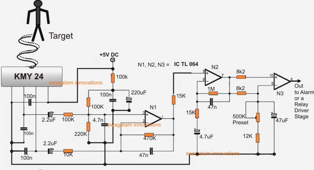
Referring to the above GHz microwave radar security alarm circuit we can see the sensor module KMY 24 configured with the first opamp stage using N1 and the associated components.
Basically N1 is wired up as a differential error amplifier, wherein its two inputs are hooked up with the two differential outputs of the sensor unit.
Detecting a Moving Object
When a moving object or target is detected in front of the sensor module the reflected GHz signals go through a relative phase shift which is reflected back to the sensor and is processed inside the module producing an equivalent positive or negative response across the center two pinouts of the KMY 24 module.
This difference in voltage is fed to the two inputs of A1 which detects this and generates an equivalent amount amplified differential voltage across its output pin#1.
A2 is configured as a filter stage which monitors the output from A1 and filters the unwanted spikes that might be induced at its input and feeds a clean amplified differential signal to the next opamp N3 stage.
N3 is connected as an impedance matching or transforming stage, which processes the fed differential input from N2 and converts it into a distinctive high or low pulses across its output pin# 8, which becomes compatible to be used with either a DC alarm stage, relay driver stage or even a Microcontroller input.
Thus the GHz microwave radar sensor alarm circuit may be used as a security system for detecting even the slightest of movements from an intruder within a 6 meter range from the sensor's emitting point, and convert into an alarm or any desired triggered output.


Questions & Answers
Good day, are there any alternatives to the KMY 24? Would a CBM 324 work instead? Thank you
Sorry, I do not have sufficient information about the alternatives of this IC, so not sure about it.
Thanks for the prompt reply. Could you suggest a website or a company where I can order this component. So far, all of my searches have come back empty
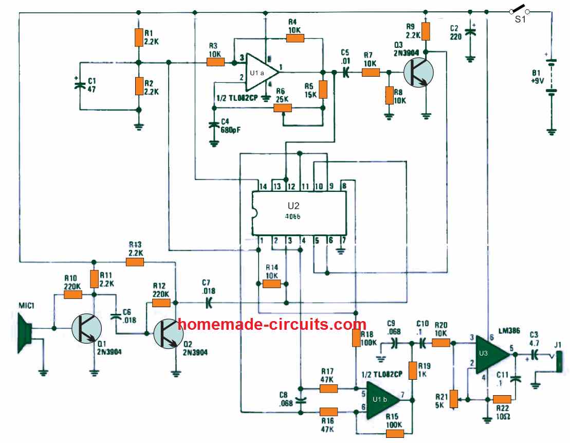
I tried to search it but could be find any helpful results. However I have another circuit which imitates the Doppler effect, using discrete components. You can check it out here:
https://www.homemade-circuits.com/motion-detector-circuit-using-doppler-effect/
Thanks for this link. I can make this circuit, but how do I connect the doppler to the security alarm?
The alarm is already included in the design. SPKR3 is for the alarm sound.
Please I need more details
I have tried to find KMY24 Microwave Motion Sensor but couldn't find anywhere. Could you please help me finding it. Although I don't need it in bulk, but I would like to work with it if I get successful with this model on regular basis. Swagatam Majumdar ji, this is one of the best diy sites I have seen. Hats off.
OK, if possible I'll inquire with my local dealer and ask him whether it is available or not in the main market Lamington Road..
Swagatam ji, I tried to find it online as well as with some vendors of Bhagirath Palace/ Lajpat Market Delhi. I am aware of its cost as I am already using HB100. So kind of you to reply on my comment. Kindly see if you or anyone on the Post could help in finding KMY24. 🙂
thank you so much Ravi, did you search the part online? I am not sure whether this would be available in common electronic part shops because it could be quite costly and not a high selling component.
you can try the following design:
https://www.homemade-circuits.com/2012/01/how-to-make-outstanding-home-theater.html
Hi Swagatam,
your project is very interesting, Could you share more about how KMY24 detect the movement approaching or receding it? They compare the differentials between 2 phase of V1out and V2out resulting in Digital output or analog. I have the project that require me detect whenever people go closed or forth the sensor to on/off the camera. Raspberry pi 4 is used like MCU control camera open or closed.
Hope to hear from you, wishing you will get more success in future and have more DIY project.
Thank you Nihat, you can get more information regarding the KMY24 in the following article:
https://www.homemade-circuits.com/using-microwave-sensor-or-doppler-sensor/
You can also have a look into the following articles which implements a similar function without depending on specialized ICs
Motion Detector Circuit using Doppler Effect
Ultrasonic Fire Alarm Circuit using Air Turbulence Detection
I want to build one stereo amplifier 2w 2w,for my pc. I want to add volume control and bass control. Suggest me a design with minimal noise and cheaper also
Hey. Now the motors are forward moving. But when obstacle is present the microcontroller cant change its port states. For ur reference m nt using a readymade kit. I have assembled the whole control ckt using atmels 8051 series chip and l293d motor driver. If u have any article regarding this.
sorry, can't figure out….presently I have not yet published any article on MCU motor control or robotics
hello. m recently workin on a obstacle avoiding bot using ir proximity sensors and At89s52 uC. Everythings ready and when i assembled it to check, it was not making the motors on.Strangely when i was testing the voltages of the pins of controller and motor drivers by touching DMM probes, it suddenly running the motors forward… iam afraid bcoz its my final year project and exam is knocking at the door.. Your suggestions will be greatly appreciated.
Hello Pritam, it would be quite difficult to judge the fault just by imagining, sorry no ideas, you may have to consult the local dealer from whom you purchased the kit.