In this post I have explained to make a simple sequential timer generator circuit which can be used for getting a sequential triggering of a connected load, or can be simply used like a sequential LED bar graph effect generator, using only transistors. The idea was requested by Mr Babusan.
Technical Specifications
Is it possible i add one more LED to this circuit but it will delay on around 2seconds after the 1st LED light up and both LED will off at the same time.
Thanks for your help.
Babusan
The Design
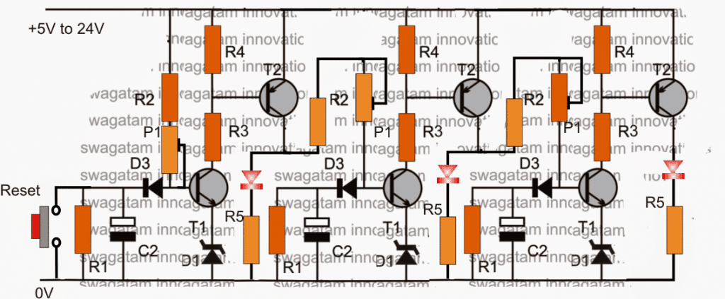
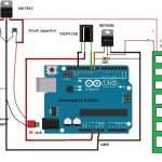
The proposed 2 LED sequential timer design can be witnessed above, it can be also used as a transistor LED sequential bar graph generator circuit.
I have shown 3 delay geneartor stages instead of two here, however any number of stages can be included as per the application specs.
Here once the circuit is powered, the LEDs are supposed to switch ON in sequence one after the other at a particular rate depending upon the values of the relevant RC components which are discretely adjustable, and may be set individually for each of the sequential stages..
Basically, the circuit is made by configuring a group of two-transistor (T1 and T2) delay ON timer stages.
Initially when power is switched ON all the LEDs or the connected loads stays switched OFF
First the extreme left C2 begins charging slowly, and after a predetermined time as set by the values of C2, R2, P1 and D1, T1 is triggered ON, with T1 ON, T2 also switches ON and the first LED from left switches ON.
With the above action T2 collector simultaneously feeds a charging voltage for the center delay timer's C2, which again repeats the cycle identically as sated above.
Due to this the center LED lights up, and its T2 feeds the signal to the right hand side stage, which goes through an identical phase illuminating the third LED in the sequence.
The situation now stays latched with all the LEDs illuminated until the "reset" switch is pressed for a few moments and released.
The pressing of the reset button enables the LeDs to shut off slowly in the reverse order sequentially.
3 Step LED Light Chaser Circuit
In case where the circuit is required to work automatically resembling an LED chaser circuit, wherein the LEDs are required to cycle sequentially creating an incrementing bar graph type sequence, and a reverse bar graph shutting off effect, the following shown design can be incorporated for the same.
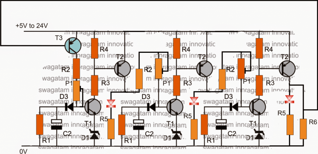
In the above concept, T3 is initially switched ON when the circuit is first powered. Once the last LED is lit, T3 is forced to shut off due to positive potential from the collector of the extreme right hand side T2 transistor. The LEDs now begin shutting one after the other with a time lapse as determined by the value of R1s.
For conditions where the LEDs are required to shut off suddenly or instantly, the above design can be modified as per the following diagram:
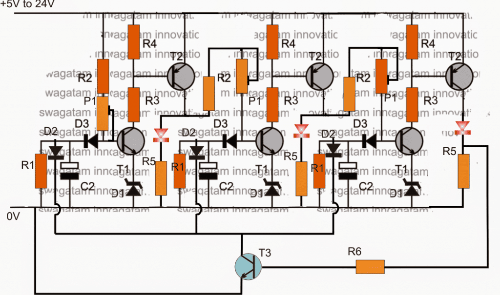
As may be seen, in the above diagram, as soon as the last LED is lit, T3 is also triggered ON, and it forces all the timing capacitor to shut down immediately or abruptly.
When this happens all the LEDs shut off, and T3 in turn is switched OFF so that the cycle is allowed to repeat once again.
Parts List
R1 = 610K (can be adjustable)
R2 = 2k2
R3, R6 = 10K
R4, R5 = 1K
P1 = 1M pot
D1 = 3V zener diode
D2 = 1N4007
D3 = 1N4148
T1,T3 = BC547
T2 = BC557
C2 = 33uF/25V (adjustable)


Comments
Also, after a sequence, can it repeat the cycle again
Yes, with the feedback loop added the circuit will keep repeating from start to finish.
https://www.homemade-circuits.com/cube-light-circuits/
Please with this circuit, what is the delay time in second to shift to the next, I want to design one that will take 10seconds interval. Thanks
Seun, you will have to confirm this practically by suitably adjusting the values of R2, C2 and P1. I do not have a formula for this RC network.
Hello.
I wonder if I may adjust this slightly.
What I’m looking for is a sequential timer, where the circuit is powered after receiving a RF signal.
– LED1 turns on for T1 time
– after T1 has passed, LED1 turns off, LED2 turns on, and T2 begins.
– after T2 has passed, LED2 is turns off, LED3 turns on and T3 begins.
I would actually like to replace the LED’s so that they trigger relays, after T1, T2, T3
Can any of the above tweaked to do that, or should I be looking at another IC/circuit ?
Thanks in advance for any assistance or pointers.
Hi, In the above sequential timer circuit the LEDs will sequentially turn ON with a delay, however once ON they will not shut off, so the LEDs will illuminate one after the other but will not shut off.
It is not possible to make the LEDs shut off for the above circuit
Thank you again!
Hi Swagatam
Thank you for the prompt reply. Pardon my ignorance in electronics, do I have to change the transistor T2 to accommodate the bigger current of 300m?
Thanks
George
Hi George, yes you will have to replace the T2 with a 2N2907, BD140 or similar
Hi Swagatam
I enjoy the advice given on this site and appreciate the time and effort you put in selflessly. Thank You.
I have a need for for 2 solenoid valves to be open sequentially after the circuit is powered. The first solenoid opens 2 seconds after activation and the second solenoid 2 seconds after the first one.
I believe that this circuit will work, however, the solenoids are 12v, 300mA each. So, I want replace the diode D1 with the solenoid or a relay. What changes will I need for the components?
I want to thank you in advance and look forward to a solution.
Regards
George
Thank you George, the solenoid should be connected in place where the LED and the R5 resistor are positioned. You can use this circuit by replacing the LEd/resistor with solenoids, appropriately. Make sure to add a freewheeling diode parallel to the solenoid coil.
Hi Swagatam,
I need a help in building a sequential led indicator with 1w leds using bc557 transistor and potentiometer to adjust the speed (no 555 n 4017 to make the circuit simple n easy).
Thanks in advance
Vinu
Hi Vinu,
you can refer to the following article
https://www.homemade-circuits.com/knight-rider-led-chaser-circuit-mains/
I’ll try to update the exact design soon for you….
Hi Swagatam,
Please find the attached link for your reference
I’m using 18 white 1w leds connected in parallel where 3leds in one connection so totally 6set(3 pcs of leds in parallel connection). I’m using the same white leds as drl n also sequential design for eye grabbing effect. Small request can you provide the final pcb design cause I’m not well verse in designing circuit sir. If possible could you able to help me in that please.
Regards,
Vinu
Sorry Vinu, designing PCB may not be possible due to lack of time. I already have a similar project but much better and accurate which is given below
https://www.homemade-circuits.com/sequential-bar-graph-turn-light/
For 1 watt leds the SCR can be C106.
Thanks Swagatam????
Regards,
Vinu
My pleasure!
Hello,
I'm trying to build a circuit that will turn on LEDs sequentially after a button press. That is, the button is pressed, then LED one lights for a time, then goes off, then two lights for a time, goes off, three lights, then goes off – then nothing until the button is pressed again. Can you help?
Hello, you can implement it by using any standard IC 555, IC 4017 chaser circuit as shown below:
2.bp.blogspot.com/-oO3I9lSCJSc/U8vm8vZf70I/AAAAAAAAHog/JvPo16mbSdY/s1600/4017+chaser+circuit.png
now do the following few modifications to it:
connect a 100k resistor between pin15 and ground, and connect a 0.22uF capacitor across positive and pin15.
disconnect pin13 from from ground and connect it with pin#7
connect a push-to-ON switch parallel wit the 0.22uF capacitor associated with pin#15.
connect 1 LED across pin3 and ground
2 LEDs across pin2 and ground
3 LEDs across pin4 and ground
all the above LEDs strings must include a 680 ohm resistor in series
however the timing cannot be changed individually for the LEDs
for individually adjustable circuit you can try the following one
https://www.homemade-circuits.com/2014/06/programmable-sequential-temperature.html
eliminate the stages associated with T3 to T9 and integrate T2 stage with the IC associated with T10.
The LEDs can be hooked across with pin3 and positive of the 3 ICs in the same manner as explained above.
Hi Swagatam
1) The first circuit is working perfectly. But the reset button switches all the LEDs simultaneously instead of delayed reverse order.
2) In the second circuit, the right most LED is continuously ON because of the emitter voltage of the left-most PNP transistor. Even if a diode is introduced between the collector of right-most PNP and the base of left-most PNP the issue is not resolved because the emitter voltage remains higher than the collector voltage hence the left-most PNP does not switch off.
One more point, you intend to fetch a control signal from the collector of the right-most PNP to reset the circuit. But this will rob the collector current hence, the corresponding LED will never light up.
yes I understood, in the first circuit you'll need to increase the value of R1 for getting a slow reverse shut off effect.
I'll try to find out another option for the second design…
Perhaps I could not explain you correctly.
In the 1st circuit, when the reset button is pressed the LEDs do not "shut off slowly in the reverse order sequentially" instead they all go off simultaneously.
In the 2nd circuit, if the base of T3 is connected to the junction of right-most LED & R5, via base resistor then the LEDs light on in sequential manner but T3 never gets switch off hence the circuit is not reset automatically.
Thank you Abu-hafss for verifying the circuits.
In the first circuit R1 decides the discharge rate of the timing capacitor C2, so by increasing the value of R1 the reverse shut off can be delayed, but the first LED will certainly shut off immediately on pressing the reset button.
for the second issue I think you can try connecting the base of T3 with the junction of the extreme right side LED cathode and R5, this might prevent the LED from staying illuminated…
T3 derives it base bias from R5, not from the collector of the right-most T2…so the collector current of T2 is not relevant to the T3 base.