The post describes a simple homemade RF signal jammer circuit that can be used for jamming any RF signal within a radial range of 10 meters. The idea was requested by one of the interested readers of this blog.
Technical Specifications
I am not a large business interest, but am in need of a circuit which would not only help me, but eventually be welcomed by just about everyone now alive.
I am in need of a circuit which will jam RFsignals. I realize jammers are illegal when they disrupt cellphone communication and commercial enterprise. I am only looking to jam (1.) remotely controlled harassment devices and (2.) spyware within the confines of my property. Jamming range limited to around a 25' x 25' area.
There is a growing community of victims of electronic harassment. We all experience an invasion of our personal lives/finances and private conversations, and are sometimes physically stalked and attacked.
Due to the nature of electronic harassment, it will take time for justice and protection to catch up and solve the problem. As for electronics, some circuits to control the misuse of flux & solder are long overdue in the marketplace.
Up until now, most of the interest has been placed on projects of invasion and abuse, such as those contained on many different website
I am not overly skilled in electronics, and only come to it in self defense. I am self taught and can follow a schematic and complete a project, and am slowly gaining understanding of the underlying theory.
Please advise regarding your interest to help, and your financial requirements. I look forward to hearing from you.
Circuit Diagram
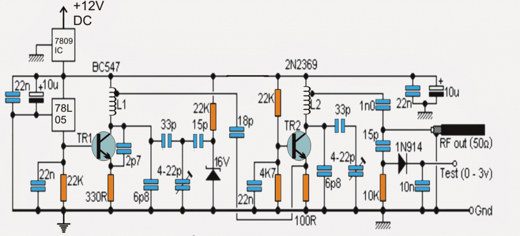
Parts List
- All resistors are 1/4 watt 5% CFR
- 22 K = 3
- 330 Ohms = 1
- 4.7 K = 1
- 100 Ohm = 1
- 10 K = 1
- Capacitors are all Ceramic Disc, unless specified
- 22 nF = 4
- 2.7 pF = 1
- 6.8 pF = 2
- 33 pF = 2
- 15 pF = 2
- 18 pF = 1
- 10 nF = 1
- 1 nF = 1
- 10 uF / 25 V Electrolytic = 2
- Trimmers 33 pF = 2
- Semiconductors
- Zener Diode 16 V 1 watt = 1
- 1N914 Diode = 1
- TR1 = BC547
- TR2 = 2N2369
- IC7809 = 1
- IC 78L05 = 1
- Inductors = See Text
- Antenna = Telescopic antenna
Introduction
A simple looking RF signal jammer circuit can be seen in the above diagram, which may be capable of jamming all sorts RF signal within the range of 5 to 10 meters.
The circuit can be made suitable with any desired frequency to be jammed by merely using different sets of L1/L2 and by tweaking the 22pF trimmers accordingly.
The frequency that could be jammed using this circuit could be well in the range of 50 MHz to 1Ghz, however making it compatible with frequencies above 500 MHz could get much complex and parameters much critical owing to the fact that higher frequencies require shorter interconnections and may involve other stability issues.
The present design can be used for jamming FM radio stations situated in the within 40 meters radial distance or even higher.
The circuity of the proposed RF signal jammer is basically made of two distinct stages:
RF Circuit Stages
The one comprising T1 and the associated parts form the RF oscillator stage while the other stage consisting of T2 and the complementing parts for amplifying and transmitting the low voltage oscillations from T1 into the air.
The above strong RF carrier signals transmitted by T2 may be appropriately modulated with any external frequency such as an audio or speech by feeding the signal across the terminal indicated "Test".
The circuit is highly stable and doesn't falter with varying input supply voltages due to the presence of the 78L05 voltage regulator at the base of T1 which clamps the base of T1 with a constant biasing current making sure that the oscillations created by the T1 stage stays very stable and consistent.
The above feature is perfectly complemented by the T2 stage which accepts the oscillations from the T1 stage and amplifies and transforms the signals with much higher current so that the signals are able to travel across larger radial distances in the air.
However in order to implement an optimal transmission of the signals, 50 OHM impedance antenna must be used with the output of the circuit.
This could be any ordinary aluminum dipole yagi antenna. A simple flexible wire measuring about a meter would also do but would reduce the transmission strength by about 60 % making the unit much inefficient as far as the transmission range is concerned.
How to Peak the Resonance
The performance of the RF jammer could be highly improved by adjusting the presets to produce peak resonance. This can be done with the following points:
- Connect a 0 - 10V DC voltmeter across the point "test" and the ground line.
- Adjust the right side 22p trimmer such that the meter reads around a maximum of 3V on the meter.
- This might disturb the initial frequency of the system that you might have set for the jamming purpose.
- So go back to the left side 22p trimmer and fine tune it again to set the desired frequency back into place.
Your peak resonance for the circuit is set now, and you can expect maximum efficiency from it.
RF Jammer Coil Specifications
For making the RF jammer compatible with other frequencies, the coil L1 and L2 must be shortened in terms of their number of turns and/or also the diameter...this will need some experimentation until the right frequency is determined.
The adjoining trimmers may also tweaked for getting an optimal response from the jammer circuit or until a perfect jamming is achieved through the circuit.
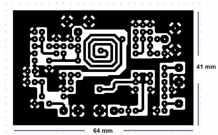
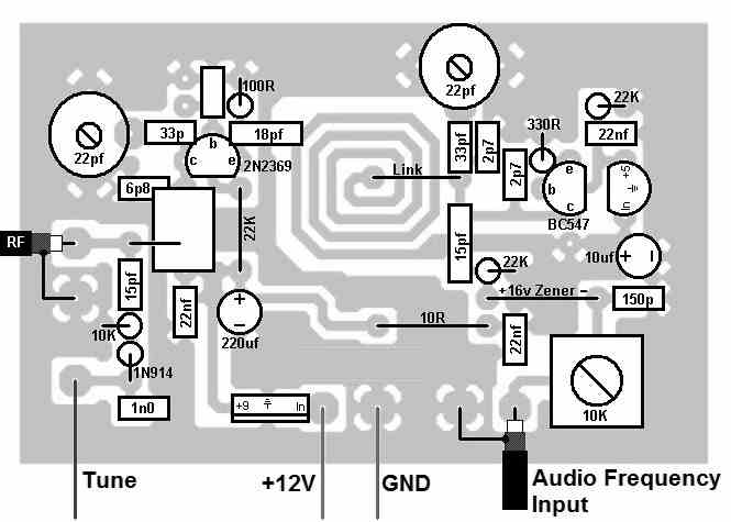
A good quality, well designed PCB is strictly recommended for constructing the RF jammer circuit
For jamming standard FM broadcasts within a range of 50 meters, L1 and L2 may be built as indicated in the following images:

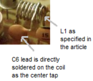
PCB Etched RF Coil
The above image shows the construction L2 using a 7 turn, 1mm super enameled copper wire with a diameter of approximately 5 to 6mm (internal)....see how the tap is extracted from the relevant end of the coil.

The following image shows how L1 can be designed by etching the tracks on the PCB itself or the same could be built using pieces of diode leads as explained in this FM wireless MIC circuit
PCB Designs


Questions & Answers
swagatam thanks for this circuit… but i just want to know can i buy these parts online ?… as trimmers and inductors are not avalaible here…. or can i buy these parts from you ?
Aqib, yes you can get everything mentioned above from any reputed online electronic store.
However please note that converting the above jammer design to a GHz range could be an extremely complex job, please proceed only if you are entirely sure about the concept and the outcomes.
Hi,
I’m intrigued by the details of making a jammer. Are there details on the listed specifications of the article, involving electronic harassment? I might relate to it.
Hi, all the relevant details are provided in the article, if you have any specific queries you can ask, I may try to help!
Hello sir, can you please send me the video of making this jammer because I want it for my project before 20 October. So please send the link as fast as possible.
yes i know that.. i olready had one circuit but there battery drainage occurs mostly and signal strength was bit slow….. swagatam in the above circuit whats the value of inductors L1 and L2??
Aqib, the values were not measured, I only have the turn data, both the coils are 5 turns, 5mm diameter using 0.8mm super enameled copper wire
Sir, We have 10 different frequencies used by cellphone providers in sweden. Does it mean that I have to build 10 different jammers to be sure that no traffic can pass? Thanks in advance
Asbjorn, all the mobiles will be jammed together which are within the range of the jammer frequency…using a single jammer circuit
kindly help which transistors T1 and T2 to be used and turns of coils in both inductance which I was unable to find in above description
I'll upadte the info soon in the article itself.
I need to jam frequency from 0-30 MHz, on 5,9,16,20,24,28 MHz. Can I do this according this link http://www.instructables.com/id/RF-Jammer/step5/Future-modificationsenhancements/ , what electronic parts "determines" max. output that jammer can offer.
Tnaks for answer, Robin.
according to the specifications of the circuit in the article it may be possible to jam those frequencies…but I cannot suggest about the parts or method, because it haven't studied the article completely..
Dear,
I need to interfere with a GPS tracker that I install my boss in my car.
Please, could you tell me how to modify this circuit to reach the 1.5 Ghz frequency?
Regards,
sorry I don’t know how to do it….
Swag
I am a X-Wife of a genuine intelligent manipulative Criminal that has made his way into my Home while having Major Surgery, & had placed what appears to be a Spy Listening Device in the South side of my Kitchen. My Son mistakenly allowed him in the House. This Device has excellent back feed Reception that appears to go directly to him. I can always tell when he has came home because the Home Noises start to occur. I want to completely Block this Man forever. He is currently under Criminal Investigation for attempted Arson, & Theft of X 2 Boats & a Pop Up Camper. I honestly beleive he wants any Heads Up that may prevent his apprehension by Law Enforcement. I have not spent Money on a Jammer Device due to the uncertainty that it would work to Block the Sound transmission to & fro. What is your recommendation? I was told by an Electrician that Magnets would skew the Device, but, thus far, these Magnets do not appear to have done the Job. I would appreciate any helpful guidance for how to begin to tackle this resistant X-Husband. Thanks, Maureen L. Walker
Hi Maureen,
I assume the frequency of the device is in the lower Mhz FM range. If it is so then the above circuit can be effectively customized to jam the device.
But the challenge is to first know the frequency of the device, which can be a difficult thing to do. Once the frequency is known it can be blocked using the above explained jammer circuit!
Another option would be to trace and locate the device and then simply destroy it manually. The tracing could be done through the following circuit. One has to build it and start scanning the walls and other intricate places until the LED lights up indicating the possible location of the bug
https://www.homemade-circuits.com/bug-detector-circuit-rf-sniffer-circuit/
I need something that can block ULF signals something in the -30dbm range I can’t pay a lot for it but if you build it and not too expensive I’d pay for it.
Sorry, have no idea about this concept, so can’t suggest much!
You are getting sound from it? It isn’t a very good device. Fact: A cheap device that is there long term must be powered from an electrical circuit nearby. Find the circuit breaker for that area, and shut it off. Have someone with really good hearing listen in the area while you turn the breaker on and off (probably every couple minutes as it will work off of a power supply and take time to discharge). The device may well make noise as it powers on and off. If not, have someone check the nearby outlets for added wires. A small device wire will be much smaller than regular house wiring.
Would it be possible to tune it to the 125-135 kHz range ?
yes, by using larger value for the 22pF trimmer
I was wondering, if by using a 555 or some other IC one could simplify the circuit. Furthermore, in my case I would like to selectively focus on a specific frequency range, could that perhaps be used to simplify it further ?
Transistors are better suited for high frequency switching and transmission, so I don’t think IC 555 will be appropriate for this application.
555 will work stable for frequencies up to 200 kHz, for higher frequencies it can be used as tank-circuit primer, but it is not suited for simple projects as it needs to be calibrated
How to increase the range of the jammer
Im simulating the whole ckt for my college project, i coudnt find the 2N2369 in multisim hence im replacing it with a 2N2222 will it still work?
2N2222 can work with up to 100 MHz frequency whereas 2N2369 is rated at 500 MHz. If 2N2222 is used then the frequency cannot be over 100 MHz.
Could you pls provide the values of l1 and l2
Sorry I have no idea regarding the coil inductance values, only the turn numbers are known to me…
Ok sir, could you provide the turn numbers as well as the area and length of the coil.
The center tap coil L2 has 7 turns, with 6 mm diameter, as shown below:
the coil L1 is as shown below
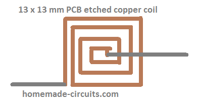
The tracks must have maximum width such that turns are separated by only 0.5 mm gap.
Hi. Is it possible to block the %G frequency. I think it is between 30 and 60 GHZ? cheers
Hi, I don’t think this circuit could be modified for GHz control!
Hi. Thanks for your response. Is it possible and is there someone I can pay to build a device to do so. Thanks
Sorry, I do have anybody within my reach at the present moment.
Swagatam,
just wanted to take the time to thank you for this post!!! I am also a TI & am building my own devices. I am perhaps much newer to the subject than you, but have been a victim for many years. I started with pc, learning ins and outs, & studied negative ions, made orgonite, human physiology, & now my journey has brought me to breadboard like yourself. I was interested to know if there is a simple solution like building a back scatter reciever or a reciever with bandwidth uhf down to sonic with a storage of said energy that will simply dissipate through resistor? Like I said I am new to this & need some basic general electrical rule education.
Hi White raven, I appreciate your thoughts very much, however, unfortunately I am myself not very knowledgeable in the field of high frequency RF circuits, since they require a lot of calculations and time. In future if I happen to gain any expertise in this field I will make sure to share the same through this website..
I’m looking for something that is directional and can jam wireless microphones that operate in the 830-860mhz range. I don’t care if it bleeds over that, and I don’t need to be able to hijack the mic output. I just need to be able to step on their mic output and stop them using their wireless mics for broadcasting their shit all over our town via loudspeaker. Something that will run on 12 or 24v would be ideal, so I can power it from my truck. I have two batteries and about a 40A alternator so I can put some current out. I can get to within 30 to 50m from the location without interference.
Sorry, I do not have a confirmed or a tested design for your requirement, if I find one will surely update it in the above post.
I once accidentally put a 13 db antenna made for 5ghz wifi on a 2.4 ghz wifi device. It effectively blocked all 2.4ghz communication for a good area around. Well enough that I was obliged to get in the car.
Maybe this could be a cheap uncomplicated alternative.
please comment.
Sound very interesting, if it worked for you then it should be worth trying for all who may be interested to accomplish identical results.
Thanks for the useful feedback!
With the new antenna the 2.4 ghz frequency, which previously carried data, now must have turned into a noisy signal. Therefore it must have acted as a signal jammer for all other 2.4 ghz devices receiving and sending data at that very frequency.
Sir what do you think? Can replacement of a mere antenna turn a good old router into a jamming device?
Sorry Abdurrehman, I have no idea about it!
I designed a circuit on proteus software according to your given circuit but I can not simulated your circuit on proteus software . what can i do? Can you please help me!
If you make it practically it will surely work, simulators are not always accurate with their results….it is tested design for jamming FM radios.
Please give me a picture of FM radio jamming/ HF /VH jamming. which circuit make a practical output and made by you. Or you can through a full video about jamming circuit, if there have no problem of you sir……
This is still very illegal to do. If a radio wave cant make it from the outside limit of your property to the opposite side you can still be charge. Get a VPN and an alarm system instead, that should protect your privacy and alert you to intruders/record trespassers at the same time without putting you in the slammer for a long time.
Can I used your jammer for HF band, like to jam between 0-30 MHz, and don’t need to be 10m, 1m would be enough, or how and what need to buy to jam something between 0-30 MHz.
Yes it can be used to jam 0 to 30MHz signals, by suitably modifying the coils L1 and L2 used in the design
Are you sure about this, what I read about jamming on net, you need actually 30% more power than transmit source, also digital modulation within HF range from 3-30MHz is harder to jam comparing with GSM or LTE signal. I like to jam two main frequency on 14MHz and 20MHz, both of tham have 3-5 digital signal around 14 and 20MHz, within 1MHz bandwith.
I didn’t catch if your jamming is device which is actually sweeper, which can made let say “white noise” between 3-30 MHz, or it’s actually jamming device which disrupt exactly certain frequency.
If I like your answer and you have spare time, and willing to earn extra money, I can hire you for some private contract.
I tested this jammer for FM radios in the range of 88MHz to 108MHz, and I could silence the music over a particular station from a distance of over 20 meters. Based on this experience I have posted this design , and I believe by suitably altering the coil dimensions the jamming frequency can be altered accordingly. Yes the jammimg power has to be higher than the source power, that is why the range distance is important, and also the antenna length.
I wish I could do it for you, however due to lack of time I may not be able to provide a practical help to you.
Hello,
What changes I need to made on coil L1 and L2, to jam this 2 major frequencies, and what is approximately price for electronic parts.
You will have to experiment by adding a few number of turns to the coil, and check the transmission frequency until it reaches the desired 30 MHz mark….you can further tweak the frequency by slightly squeezing or stretching the turns of the coil.
Thanks, but you didn’t answer about price for electronic parts, when you made schematic, presume that you calculate price for jammer.
You can get the price from any online electronic spare part store
Yes inducing a white noise at the base of the left transistor can enhance the effect of the jamming a lot
So can you provide a parts list please ?
Hello,
Please, can you share your mail, or some contact, like to exchange ours achievement, think that we are in the same boat.
I take it the electronic harassment you talk about is the Cuban syndrome type or what TI’s call v2k correct?
If so I’ve bought two Jammers that are supposed to jam various signals and different frequencies and channels, but don’t seem to do much. I use a EMF meter to see what’s going on when they’re on, and seem to be doing something, but still I hear this crap. I use a software that I can record the stuff that’s illegally sent to me and on the settings it has TFFT thing that shows all the frequencies and the highest points while playing the recording back. The last reading I got was 4484hz -4499hz but at times it can go as high as 800 or more hz so I need a RF Jammer that could cover that. I also found a tool that shows me what applications are used at these frequencies and on the chart it shows Radars, mobile phones, and commercial wireless.
It also shows that it’s at a super High frequency, so I need something that would jam that any ideas?
and that diagram above have you made it yet and plan on making those for sale? I’ve read on other sites that an analog jammer would be best since digital jammers are too easy for the perps the criminals to hack. I have no idea how to do the above schematic I have no electronics engineering knowledge whatsoever so I need one built for me.
Thank you for the detailed explanation, I understand you want to build a good jammer circuit, however, if you do not have any prior knowledge or experience in the field of electronics, then the above project can be virtually impossible to build and test for you. Providing a ready made kit may not be possible either since the above circuit will require a PCB which is not available with me at this moment of time.
Just reading all of this and I’m tired. Great job buddy!
Hi swagatan
I am just saw your design now but I didn’t built it to see whether it is working or not but I really appreciate how you are responding or answering questions.
Thank you
Thank you Muhd, I appreciate your response. Let me know if you have any further questions.
I like building things, it is the way I learn. Whats the chances of getting a kit for the signal jammer?
I am glad you are learning the procedures, however getting a ready made kit may not be possible at this time.
Thank you for your reply. I’ll look into getting breadboards.
Breadboard might not work since it is a sensitive RF circuit….you will have to solder the items on a strip board to get proper results…
Want to buy a ready to use radar police jammer, for long range.
Please contact me.
Thanks,
Roni Blum
GOOD AFTERNOON. YES, I WOULD LIKE TO KNOW HOW TO GET ONE. I ALSO A, TRYING TO MAKE A LASER AUDIO LISTENING DEVICE BUT SINCE I DO NOT HAVE THE EXPERIENCE TO UNDERSTAND WHAT IM DOING, I NEED ADVICE. I WOULD LIKE TO KNOW IF YOU PROVIDE CLASSES OR JUST ASSEMBLED? THANKS CARLOS
I am in great need of a signal blocker as I am highly sensitive to several frequencies resulting in terrible headaches and insomnia. I really only need it for 1 level 40’×30′ in my home.
Can someone help me, please?
Thanks so much.
I believe it could be just a psychological problem, you must consult a Doctor before thinking about installing electronic devices or signal blockers.
A Jammer would be much worse. They are the equivalent of shouting over the original signal to drown it out.
Well can I use this circuit to jam signals with Frequencies between 600MHz and 2.5GHz ?
If it can’t handle what kind of modifications do I need to do to reach that frequency.
If you reduce the number of turns of L1 and L2, or if you stretch the coil wide apart then its transmitting frequency will also increase proportionally. However I don’t think this jammer will be able to handle above 1 GHz. And as the frequency is increased the part terminals will need to be reduced significantly, or SMD parts will need to be employed.
Well atleast is it capable of blocking some amount of mobile signal….?
And one more thing what are the test (0-30V) and RF out 5ohms.
RF out must be the output antenna for the signals. Is it….?
I also would like to know how to connect the RF out. Practically.
0-3V is the test output, and 50 ohm RF is output for the antenna…I have explained them in the article. You can connect a TV dipole antenna to the 50 ohm RF output points
Did it help? I am literally experiencing this exact situation in my home as i believe all my neighboring households are as well.
Please erite me 6025159295, or 4803769819
Pleasee! I am desperate!!!
Can I use regular copper wire for the coil?
Use Super enameled copper wire or magnet wire.
I am wanting to make a signal jammer for adjustable capitator 5pf-20pf to name a 13.56 Mhz. What all components would I need to complete this circuit. Where can I get a circuit board to make it?? What site sells these components. I got a adjustacle capitator from eBay. Here is my cell # 14056279236
I have updated the parts list and the PCB design for the convenience of the users. You can get the parts from any online spare part retailer store.
Is the components on here for a signal of 13.56 with a trimmer capitator? Cuz I’m not for if it’s exactly 13.56 just guessamtion
The components are for 100 MHz jammer. You may have to reduce the number of turns on the coil or stretch the coil to widen the distance between the turns in order to achieve a 13 MHz frequency.
Like antenna coil
Yes, just as we adjust the antenna coil.
Is there a way I get a signal jammer that’s 13.56 can get jammed. With the trimmer capitator. Or have some make it or just the parts and circuit board????
You will have to adjust the parallel trimmer capacitors, and also adjust the antenna coil winding for getting the desired frequency jamming.
salut, j’avais également une question: celle de savoir si ce jammer est efficace pour les digital remote controller de 315/433 Mhz
Hi, You will have to adjust the 22pF trimmers and also the L1 L2 appropriately for jamming the desired 433 MHZ frequency
Hello I am a middle aged woman alone under horrendous cyber attack visual and audio in my home and car I need help desperately I am unable to make this device I so urgently need. It is the most difficult and scary and violating feeling I have ever had in my life
hello, I would like to know how to check that we have reached the frequency of 433Mhz for example
You will have to keep a 433 Mhz receiver and transmitter switched ON such that the receiver is tuned and activated by the transmitter. Then tune the jammer until the 433Mhz receiver’s switch ON response breaks.
Hello sir, can you please make a little big size jammer so that I can make this in my project and also please send the link of video of making it.
Hello Abhay,
Making a video can be difficult for me due to lack of time.
I had tested this circuit long ago and it worked very nicely. I could jam most FM radio signals within 100 meter range using this jammer circuit.
Since I adjusted the circuit between 90 and 110 MHz I could jam FM signals within this range, however this frequency could be changed to other MHz values to jam other desired signal ranges also.
Can I use it to jam mobile phones signal also
For jamming mobile phone you may have to set the frequency to GHz level, which can be very difficult and complex.
Hi sir, can you tell me how many types of RF signal will it jam and what is the maximum range of it to jam
Hi Abhay, You can customize the circuit to any desired frequency range, but as you increase the frequency you will need to strictly optimize the layout by the circuit by making the interconnection shorter and the inductor also will need to optimized with lot of care. All these can be very complex unless you are an expert with RF circuit designs.
What does that mean???