In this post I have explained a simple water sensor with pump starter circuit for switching a pump motor during municipal water supply periods. The idea was requested by Mr. Hitesh Thapa.
Technical Specifications
Is it possible to make a automatic water pump starter which turns On only when the city supply line has water flowing.
Here is the scenario.
- City Supply Line opens only for 1 hour anytime during 6AM - 10AM or rarely sometimes in the evening depending on the water guy.
- We need to keep a watch during these times and keep the main tap open to see if the water has come.
- Once the water has come, we turn on the water pump attached to the main supply line to pump water into our underground water tank.
Could this be automated, like we install some sensor between the water pump and the main supply line that detects water and turns on the motor only when the supply is in full flow?
I have made the water level indicator at home from watching some videos online and it works fine for the overhead tank at home but this one seems to be tough nut to crack :).
Any help is highly appropriated.
Thanks,
Hitesh Thappa
Circuit Diagram
Parts List
- Resistor 1k, 1/4 watt, 5% CFR = 1 no
- Capacitor 10uF/25V Electrolytic = 1 no
- Transistor TIP122 = 1no
- Relay 12V/30 Amp/ SPDT = 1no
- Diode 1N4007 = 1no
- Stainless steel metal for the probes
- 220 V AC to 12 V DC adapter = 1no
The Design
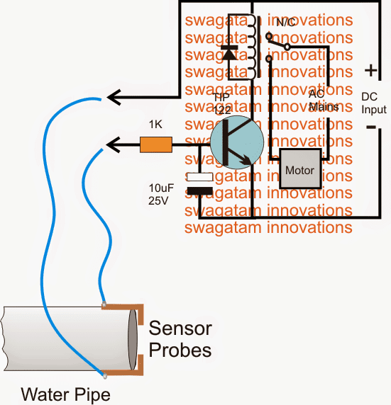
The circuit design of the proposed municipal water sensor with pump starter is very simple as may be witnessed in the shown diagram.
A Darlington TIP 122 transistor becomes the main active sensing device in the circuit. The device being a Darlington is very sensitive and thus becomes specifically suited to the application.
Its base and the positive DC are together clamped as probes across the water pipe mouth where the incoming utility water is intended to be sensed.
In absence of water the probes stay separated with air gap which renders a very high resistance across the probes which in turn keeps the transistor/relay stage switched off.
The 10uF capacitor at the base of the transistor ensures that the transistor does not get rattled or disturbed by external noises trying to make way through the sensor wires.
When utility water supply initiates, the pipe mouth begins throwing water into the adjoining tank, the speed of the water through pipe brushes across the probes creating a relatively low resistance across it.
This low resistance allows the positive DC to reach the base of the BJT triggering it into conduction...the transistor now conducts and switches ON the relay, the relay contacts shift position and switch ON the connected pump.
Upgrading the above municipal water sensor into an overhead tank overflow cut off circuit
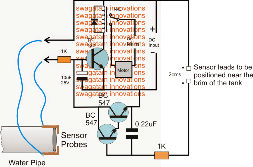
The discussed circuit in the above section can be appropriately enhanced with an additional feature which will enable the circuit to sense an overhead tank full situation and switch OFF the relay along with the pump motor. The upgraded circuit design can be viewed below:
Parts List
- Resistor 1k, 1/4 watt, 5% CFR = 2 no
- Capacitor 10uF/25V Electrolytic = 1 no
- Capacitor 0.22uF PPC = 1no
- Transistor TIP122 = 1no
- Transistor BC547 = 2nos
- Relay 12V/30 Amp/ SPDT = 1no
- Diode 1N4007 = 1no
- Stainless steel metal for the probes
- 220 V AC to 12 V DC adapter = 1no


Discussion & Solutions
Required support to repair the electronic circuit
How much DC voltage do I need for this?
will depend upon the relay voltage spec used, if it's 12v then the supply can also be 12V and so on.
you can refer to the following article, the relay explanation along with its specs are provided here
https://www.homemade-circuits.com/2012/01/how-to-understand-and-use-relay-in.html
very helpful thank you
Dear Swagatam Majumdar,
The project (Municipal water supply sensor, pump controller circuit) circuit diagram doesn't show on your site. please send me circuit diagram at email id: faisalpasha9090@gmail.com
thanks!
Dear Faisal, it could be your ISP problem, please read this:
https://www.linkedin.com/pulse/20140620140349-53089235-blogspot-down-in-pakistan
Finally I got circuit diagram from Google images, Mr. Swagatam Majumdar can you tell me how much voltages is required to run this circuit because i'm mechanical student I've not enough knowledge about electronics circuit.
Faisal, you can operate it with 12V… if the relay is also 12V rated, or any voltage that matches the relay coil voltage
Hey.. Appreciated your project.
I have one doubt.
What type of sensor probes being used?
thanks meet, you can use brass terminals with solder plating as the probes.
ok. thank you so much.
should I use single channel relay on 3 phase motor or else double channel relay is suitable for the same?
for 3 phase motor you will require a TPTT relay or 3-pole relay with heavy duty contacts
Ok. Thanks. Because single channel relay can conduct only DC supply.
relays can conduct AC/DC both, but in 3 phase there are 3 lines therefore 3 contacts would be required, a single contact relay cannot work
Thanks a lot. Now I got the whole scenario.
As you said I purchased 3 pole relay of PLA company (3C/O MPC 12D-5) having 11 pin encircled. It has 3 pole so on 3 common , 3 N/C and 3 N/O. Now how should I make a connection of 3 phase motor with this relay? please help me out.
sorry I made a mistake. There is a single phase motor, not three phase motor. So i got solution. Thanks.
OK, in that case you can use a regular SPDT relay with 30 amp contacts.
How should I make water level controller system in this same circuit? So that after filling tank the motor will automatically turn-off, please guide me.
I'll try to upadte the idea in the above article soon…
No problem. Thanks.
Hello sir, have you thought on that new concept which I requested earlier?
Meet, due to lack of time I could not do it, will try to update it soon…
….I have updated the new design at the bottom of the article.
Great. Now this would become Dual functionality embedded in one circuit only. Thanks a lot.
My pleasure!!
Respected sir,
as per this circuit diagram and instruction build the same but i dint get result , would u can mail me with details .progressofganesh@gmail.com
Ganesh, the concept explained is very straightforward and should work without fail, you might have done something incorrect in your design…
you can confirm the results using a cup of water and immerse the sensor points inside it to check whether the relay clicks or not…
…you can also try reducing the 10uF to 1uF for better response
I want to buy a 'READY TO USE' Controller
which can Switch – On the pump, when it detects
water flow from the City's supply and when
the same stops, it Switch – Off the pump. Has
any company incorporate this circuit design in
their Controller device ? And if so, please list
the name and contact info. Thanks
Sudhir
Gurgaon HR
April 27, 2017
Note: Needless to say, the controller, should have
other features, like Switch Off the pump, when tank
gets filled
good day sir
i need acircuit which detects water flow and giving indication of same when pump starting to fill the overhead tank . we are using pvc pipes and what kind of snsor probs can be used instead of brass for effctive response
john
good day sir
is it possible to use probe be made off aluminium ( easily avaliable from home utensil) instead of brass ( not easily availiable in my place )
john
good day john,
you can try the same circuit which is explained above, for indication you can connect an LED in series with the base of the transistor.
for the sensor aluminum will work but aluminum may be also prone to oxidation. instead you can use copper and tin it with a thick layer of solder…the solder should be of the highest grade with a tin/lead ratio of 60/40…or better.
thank you sir for ur kind advice one more query how much should be the gap need to maintain between the sensor probes and voltage to supply ( our supply pipe is 1.5 inch dia )
john
the distance could be around 1cm, but make sure that it is built in such a way that water does not clog between this gap when water supply has stopped.
Hello I want ready ckt is available in any where
sorry, there's no readymade unit available from here..
Is it not possible to use 12v AC instead of 12v DC ? A transformer could be used to convert 220v AC into 12v AC ?
It is possible, but the circuit could be come a little complex…
Complex in what way ? Also, I am not able to find the Tip122 Darlington transistor, is there any substitute for it ? Does relay work in both AC and DC or is there different type of relay for different current ? And will 12v relay work for this circuit ?
Many thanks for the reply.
You can replace the TIP122 by manually making a Dalington using a 2N2222 and TIP31
A relay will work only with DC, not with AC unless its rectified
I have designed an anti-corrosion related circuit below, you can check it out:
https://www.homemade-circuits.com/2017/06/anti-corrosion-probes-for-water-level.html
you ca use the relay which is shown in the following article
https://www.homemade-circuits.com/2012/01/how-to-understand-and-use-relay-in.html
Hi Swagatam,
The circuit is working fine. Request you to suggest a suitable modified circuit for eliminating the problem of pump frequently switching on off frequently during the starting few minutes of water supply. I wish once the pump is started should not go off for a couple of minutes even if the sensor are sensing water and air in sequence until the supply is stable.
Hope I am clear.
Thanks in advance.
Hi Imtiyaz, I am glad it is working for you!
To solve this you can add a 470uF/25V capacitor across the relay coil, this will make sure that the relay does not stutter during the initial fluctuating water supply conditions.
The shuttering still persist, without resolving continuous practical application is not possible.
As I am a mechanical engineer, request you to forward a complete circuit with discussed modification and introduction of selector switch for auto and manual selection. It would be more asthetic if led indicators are also introduced.
My e-mail id is
imtiyaz_ur@yahoo.co.in
Thank you
Hi, did you connect the capacitor across the relay coil? Even after you connect it if the water supply is too much fluctuating with large delays between ON and OFF then the relay will stutter,and cannot be solved with the above simple circuit.
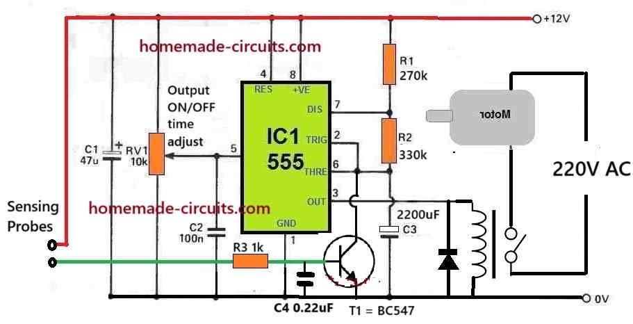
In that case you will have to build a IC 555 monostable circuit and use it.
build the circuit which is shown in the following article
https://www.homemade-circuits.com/intruder-position-indicator-security/
remove the piezo, and connect the two wires with the water pipe probes.
remove the LED, resistor, and replace it with a relay, make sure to connect a diode across the relay coil.
The 1M pot will need to be correctly adjusted such that the stuttering just stops.
Thanks for the guidance,
All the 3 parts are working
A)Water sensing to start pump
B)Time delay to stop shuttering
C)Overflow pump stopping
Now one small problem, when incoming water stopped#pump goes off
But a slight residue water in the pipe touches the sensor the pump is restarted, how can this issue be tackled?
That’s great! I am glad it’s serving the purpose for you.
To solve the present issue, You will have to position the sensor in such a way that the water touches the sensor only when there’s some force in the water, otherwise without any force the residual water should be unable to come in contact with the sensor points.