• Skip to main content
  • Skip to primary sidebar

Homemade Circuit Projects

Need circuit help? Post them in the comments! I've answered over 50,000!

Blog | Categories | About | Hire Me | Contact | Calculators-online
You are here: Home / Sensors and Detectors / MQ-135 Air Quality Sensor Circuit – Working and Interfacing with Program Code

MQ-135 Air Quality Sensor Circuit – Working and Interfacing with Program Code

Last Updated on August 9, 2019 by Swagatam 17 Comments

In this article I have explained how to interface air quality sensor MQ-135 with Arduino. We will see overview of the sensor and construct a project which detects LPG gas leakage and see some relevant readings in serial monitor.

Table of Contents
  • What is MQ-135 sensor?
  • Typical MQ-135 sensor:
  • The circuit:
  • Program:

What is MQ-135 sensor?

MQ-135 is an air quality or air pollution measuring sensor device. It can detect various chemical contents in air and give appropriate voltage variation at the output pin depending on the chemical concentration in air.

It can detect alcohol, Benzene, smoke, NH3, butane, propane etc. if anyone of the stated chemical concentration rises, the sensor convert the chemical concentration in air to appropriate voltage range, which can be processed by Arduino or any microcontroller. It cannot tell what kind of chemical concentration rose in the air.

Typical MQ-135 sensor:
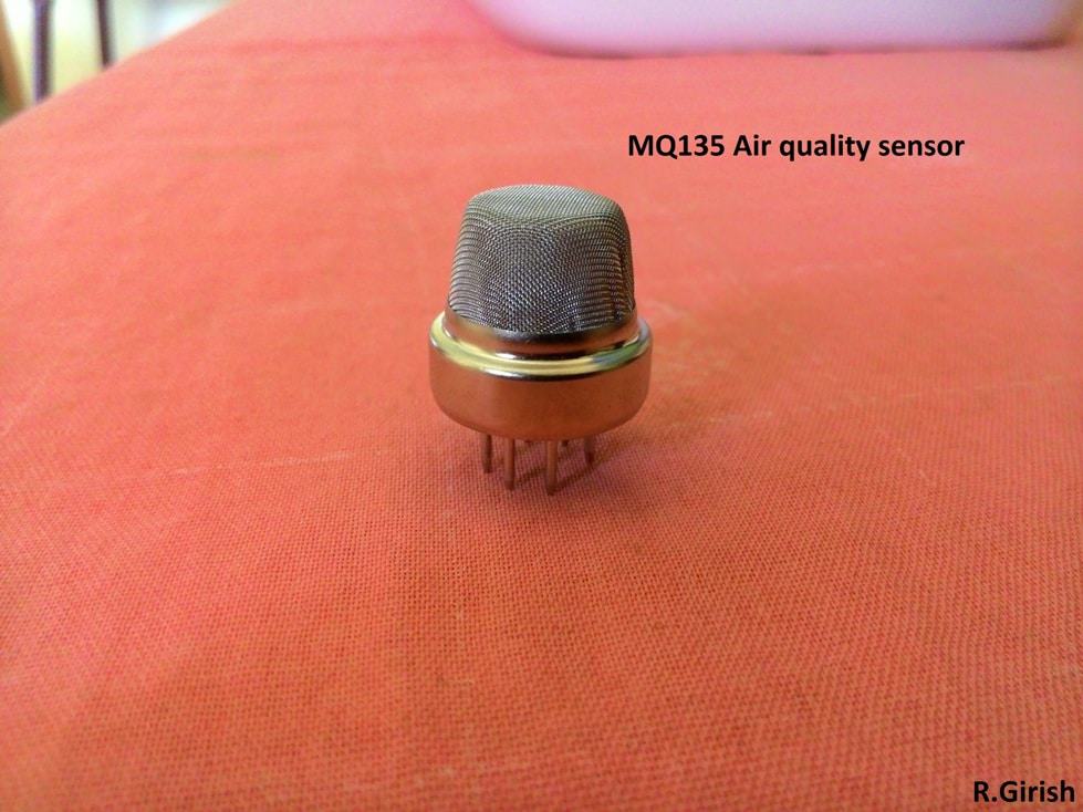
MQ135 air quality sensor module

It is 6 terminal device which is symmetric in terminal placement; both the sides of the terminal are interchangeable. Here is the illustration of pins:
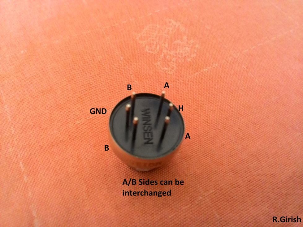
MQ135 pinouts

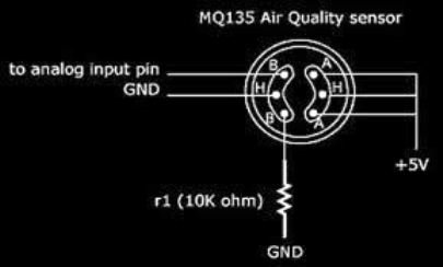
Here is a basic connection diagram:

Two ‘A’ pins are shorted internally and two ‘B’ pins are shorted internally. H and H pins is heater coil of the sensor. The heater coil is used to heat up the air around the sensor, so that it can detect the chemical content in the air optimally.

The sensor can take up to few minutes to heat up to reach optimal working condition. It not advisable to touch the sensor while operating because it can get pretty warm.

The sensor has an operating voltage of 5V; the sensor must be powered from external sources only, as it consumes about 200mA for heating. The arduino voltage regulator can’t deliver this much current.

For testing, you can connect a ammeter in mA range at the output pin B and bring a cigar gas lighter. Try to leak the gas without igniting it near the sensor. As the concentration of gas rises around the sensor, the current flow through ammeter increases. If this works, your sensor is working normally.

Now, you know quite a bit about MQ-135 Sensor, let’s move ahead and learn how to interface the MQ-135 with Arduino interfacing.

The circuit:
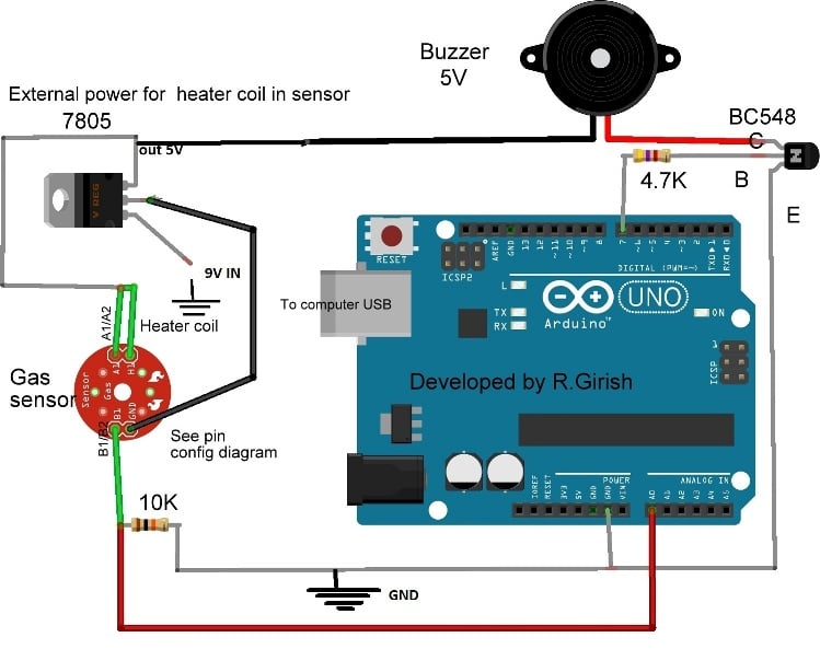
Arduino MQ-135 Air Quality Sensor Working and Interfacing

Make the connections as per the diagram, and check the gas sensor wire connection etc. Rest of the circuit is self explanatory.

The analogue pin of Arduino measures the voltage from the gas sensor. When the gas concentration rises above preset threshold in the program, the buzzer starts beeps.

The sensor takes a couple of minutes or so to warm up to reach optimal operating condition. Until it reaches optimal working temperature, the values in the serial monitor fluctuates high and low. It stabilizes after few minutes.

In the program the user can set the threshold value, it must be done only after careful observation on normal ambient concentration value in the serial monitor. For instants, if the value fluctuates from 400 to 430, the threshold must set well above, like 500. It must not trigger the buzzer falsely.

The values displayed in the serial monitor are NOT ‘ppm’ level of chemical concentration or anything like that. It is mere measure of voltage level from the sensor; Arduino interprets the value from 0 to 1023. So we can say, higher the chemical concentration, higher the values get displayed.

Program:

//-------------------Program Developed by R.Girish-----------------//
int input = A0;
int output = 7;
int th=500; // Set threshold level.
void setup()
{
Serial.begin(9600);
pinMode(output,OUTPUT);
digitalWrite(output,LOW);
}
void loop()
{
Serial.println(analogRead(input));
if(analogRead(input)>th)
{
digitalWrite(output,HIGH);
}
else
{
digitalWrite(output,LOW);
}
delay(500);
}
//-------------------Program Developed by R.Girish-----------------//

The serial monitor is not mandatory in this project it also works as standalone; we need it only to calibrate the threshold value in the program.

Set the threshold value by changing:

int th=500; // Set threshold level.

Replace 500 with your value.

This concludes the article regarding how to interface MQ-135 air quality sensor with Arduino, for further queries you can post your thoughts through your comments.

You'll also like:

  • noncontactacsensorNon Contact AC Phase Detector Circuit [Tested]
  • irSENSORCIRCUITTuned Infrared (IR) Detector Circuit
  • DHT11 Humidity, Temperature Sensor: How to Use and Interface with Arduino
  • ultrasonic receiver compressedUltrasonic Detector Circuit [Extend your Ear’s Sensitivity]

Filed Under: Sensors and Detectors Tagged With: 135, Interfacing, MQ, Quality, Sensor, Working

About Swagatam

I am an electronics engineer and doing practical hands-on work from more than 15 years now. Building real circuits, testing them and also making PCB layouts by myself. I really love doing all these things like inventing something new, designing electronics and also helping other people like hobby guys who want to make their own cool circuits at home.

And that is the main reason why I started this website homemade-circuits.com, to share different types of circuit ideas..

If you are having any kind of doubt or question related to circuits then just write down your question in the comment box below, I am like always checking, so I guarantee I will reply you for sure!

Previous Post: « How to Make a Transformer Winding Counter Circuit
Next Post: “WELCOME” LED Display Circuit »

Reader Interactions

Questions & Answers

Total Posts: 17
Newest Oldest
muhammad saifullah
November 19, 2020 • 6 years ago #84640

hello sir, I’m electrical students, I want to make this project. I want to know how to draw the circuit using Proteus 8 Professional. And how to insert the code to the circuit. I hope you can help me.

Reply
SwagatamAdmin
November 20, 2020 • 6 years ago #84698

Hello Muhammad, sorry I do not use software for testing my circuits, instead I test them practically, so I can’t suggest much regarding them.

Reply
Gautam Gupta
August 17, 2019 • 7 years ago #69398

What is the name of this circuit?? And how can we purchase this in local markets??

Reply
SwagatamAdmin
August 18, 2019 • 7 years ago #69408

Air Quality Sensor!

Reply
Babatunde
July 22, 2019 • 7 years ago #68681

Am still expecting your promise. Thank you

Reply
Babatunde
April 8, 2019 • 8 years ago #66364

thanks for this good work.
please i would like to have the one I can use MQ135 module and LCD 16 x2 with the code. thanks

Reply
SwagatamAdmin
April 8, 2019 • 8 years ago #66369

Thanks Babtunde, I’ll try to find if I get I’ll may update it here for you!

Reply
Babatunde
April 8, 2019 • 8 years ago #66371

Oh, I will so much appreciate that. Thanks a lot

Reply
Babatunde
May 23, 2019 • 7 years ago #67209

Please do not forget to send me my request when you have it. Thanks in anticipation.

Reply
SwagatamAdmin
May 24, 2019 • 7 years ago #67214

Sure, I am trying but no luck so far!

Reply
bashir abdulkadir
September 24, 2016 • 10 years ago #44981

Thank u sir. and my another question is that can any inverter work with any transformer like 6-0-6, 12-0-12 and so on according to watt i require and i know if i used 6-0-6 transformer the battery must be 6v the same with 12-0-12 battery must be 12v Sir may i correct or not ?

Reply
SwagatamAdmin
September 25, 2016 • 10 years ago #45009

Bashir, all transformers can be used for inverter application, but the operating voltage needs to be approximately equal to its primary winding voltage rating…so a 6-0-6 will require a 6V batt, a 12-0-12 will require a 12V batt and so on

Reply
bashir abdulkadir
September 23, 2016 • 10 years ago #44941

sir if i want connect transistor six TIP35C in pararell may i going to connect based to based emitter to emitter collector to collector ?

Reply
SwagatamAdmin
September 24, 2016 • 10 years ago #44955

Bashir, that's possible but make sure to connect all the transistors over a common heatsink

you can refer the following article for more help

https://www.homemade-circuits.com/2011/11/transistor-facts.html

Reply
bashir abdulkadir
September 23, 2016 • 10 years ago #44927

thanx sir

Reply
bashir abdulkadir
September 21, 2016 • 10 years ago #44819

sir can i substituate NPN transistor with any NPN transistor even if ther values are not the same ?

Reply
SwagatamAdmin
September 21, 2016 • 10 years ago #44825

yes you can, but preferably their main specs should be similar.

Reply

Need Help? Please Leave a Comment! We value your input—Kindly keep it relevant to the above topic! Cancel reply

Your email address will not be published. Required fields are marked *

Primary Sidebar

My YouTube Channel

Circuit Simulator: Draw and Simulate Schematics

circuit simulator image

Categories

  • Arduino Projects (95)
  • Audio and Amplifier Projects (134)
  • Automation Projects (18)
  • Automobile Electronics (104)
  • Battery Charger Circuits (90)
  • Datasheets and Components (109)
  • Electronics Theory (151)
  • Energy from Magnets and Earth (43)
  • Games and Sports Projects (11)
  • Grid and 3-Phase (20)
  • Health related Projects (27)
  • Home Electrical Circuits (13)
  • Indicator Circuits (16)
  • Inverter Circuits (98)
  • Lamps and Lights (161)
  • Meters and Testers (72)
  • Mini Projects (28)
  • Motor Controller (68)
  • Oscillator Circuits (30)
  • Pets and Pests (15)
  • Power Supply Circuits (91)
  • Remote Control Circuits (50)
  • Security and Alarm (65)
  • Sensors and Detectors (107)
  • SMPS and Converters (46)
  • Solar Controller Circuits (62)
  • Temperature Controllers (44)
  • Timer and Delay Relay (51)
  • Voltage Control and Protection (44)
  • Water Controller (37)
  • Wireless Circuits (31)

Subscribe to get New Circuits in your Email

Other Links

  • Privacy Policy
  • Cookie Policy
  • Disclaimer
  • Copyright
  • Videos
  • Sitemap

People also Search

555 Circuits | 741 Circuits | LM324 Circuits | LM338 Circuits | 4017 Circuits | Ultrasonic Projects | SMPS Projects | Christmas Projects | MOSFETs | Radio Circuits | Laser Circuits | PIR Projects |

Recent Comments

  • Swagatam on Electronic Circuit Projects, Tutorials, and Practical Engineering Solutions
  • Swagatam on Inverter LC Filter Calculator
  • Swagatam on Electronic Circuit Projects, Tutorials, and Practical Engineering Solutions
  • Mazlom on Electronic Circuit Projects, Tutorials, and Practical Engineering Solutions
  • brian khisa on Inverter LC Filter Calculator

Social Profiles

  • Twitter
  • YouTube
  • Instagram
  • Pinterest
  • My Facebook-Page
  • Stack Exchange
  • Linkedin

Calculators

  • ZVS Induction Heater + Tank Calculator Tool
  • Zener Diode Calculator
  • Wire Current and Thickness Calculator (Ampacity Calculator)
  • Voltage Divider Calculator
  • Transistor Base Resistor Calculator
  • Transistor Astable Multivibrator Calculator
  • TL431 Calculator
  • Solar Panel, Inverter, Battery Calculator
  • Ferrite Core Air Gap Calculator Tool
  • Parallel MOSFET Calculator Tool: How to Connect MOSFETs in Parallel Safely
  • LC Resonance Calculator for EV Battery Charger Circuits
  • LED String Series Resistor Calculator
  • PFC (Power Factor Correction) Calculator Tool: 3kW
  • Passive Power Factor Correction (PFC) Calculator
  • LM567 IC Calculator Tool
  • SMPS Flyback Boost Converter Calculator
  • Shunt Resistor Calculator for Ammeters
  • SCR and Triac Gate Resistor Calculator
  • Battery Back up Time Calculator
  • Boost Converter Calculator (Non-Isolated)
  • Bootstrap Capacitor Calculator
  • Buck Converter Calculator
  • Buck-Boost Converter Calculator
  • Capacitance Reactance Calculator
  • DCM Flyback Transformer & Wire Gauge Wire Size Calculator Tool
  • Filter Capacitor Calculator
  • IC 4047 Calculator (Frequency and PWM)
  • IC 4060 Calculator
  • IC 555 Astable Calculator
  • IC 555 Monostable Calculator
  • IC SG3525, SG3524 Calculator
  • Inductance Calculator
  • Induction Heater Inductor and Resonant Frequency Calculator
  • Induction Heater Work Coil Calculator
  • Inverter LC Filter Calculator
  • LC Resonance Calculator
  • LED Current Calculator
  • LM317, LM338, LM396 Calculator
  • NAND/NOT Gate RC Values Calculator
  • NOT, NAND Gate Frequency Calculator
  • Notch Filter Calculator Tool
  • Ohm’s Law Calculator
  • Phase Angle Phase Shift Calculator
  • Power Factor (PF) Calculator
  • RC Filter Calculator
  • Reactance Calculator
  • Sine Table Calculator for SPWM Arduino Code
  • Small Signal Transistor(BJT) and Diode Quick Datasheet
  • SMPS Calculator for Toroidal Ferrite Transformers
  • SMPS Flyback Transformer Calculator – Design by Target Duty Cycle
  • TL431 Calculator
  • Op-Amp Hysteresis Resistor Calculator

© 2026 · Swagatam Innovations