In this brief tutorial I have explained how to design a customized UPS circuit at home using ordinary components such as a few NAND ICs and a some relays.
What is an UPS
UPS which stands for uninterruptible power supply are inverters designed to provide a seamless AC mains power to a connected load without a slightest bit of interruption, regardless of sudden power failures or fluctuation or even a brown-out.
An UPS becomes useful for PCs and other such equipment which involve critical data handling and cannot afford mains power interruption during a vital data processing operation.
For these equipment UPS becomes very handy due to its instantaneous power back-up to the load, and for providing the user with ample time to save computer's crucial data, until actual mains power is restored.
This means that an UPS must be extremely quick with its changeover from mains to inverter (back up mode) and vice versa during a possible mains power malfunction.
In this article I have explained how to make a simple UPS with all the bare minimum features, ensuring that it conforms with the above fundamentals and provides the user with a good quality uninterrupted power throughout the course of its operations.
UPS Stages
A basic UPS circuit will have the following fundamental stages:
1) An inverter circuit
2) A Battery
3) A battery charger circuit
4) A changeover circuit stage using relays or other devices such as triacs or SSRs.
Now I have explained how the above circuit stages may be built and integrated together for implementing a reasonably decent UPS system.
Block Diagram
The mentioned functional stages of an uninterruptible power supply unit could be understood in detail through the following block diagram:
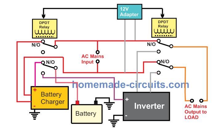
Here we can see that the main UPS changeover function is carried out by a couple of DPDT relay stages.
Both the DPDT relays are powered from a 12 V AC to DC power supply or adapter.
The left side DPDT relay can be seen controlling the battery charger. The battery charger gets powered when AC mains is available through the upper relay contacts, and supplies the charging input to the battery via the lower relay contacts. When AC mains fails, the relay contacts changeover to the N/C contacts. The upper relay contacts switches OFF power to the battery charger, while the lower contacts now connects the battery with the inverter to initiate the inverter mode operation.
The right side relay contacts are used for changing over from grid AC mains to the inverter AC mains, and vice versa.
A Practical UPS Design
In the following discussion I will try to explain and design a practical UPS circuit.
1) The Inverter.
Since an UPS has to deal with crucial and sensitive electronic appliances, the involved inverter stage must be reasonably advanced with its waveform, in other words an ordinary square wave inverter may not be recommended for an UPS, and therefore for our design we make sure that this condition is aptly taken care of.
Although I have posted many inverter circuits in this website, including sophisticated PWM sinewave types, here we select a completely new design just to make the article more interesting, and add a new inverter circuit in the list
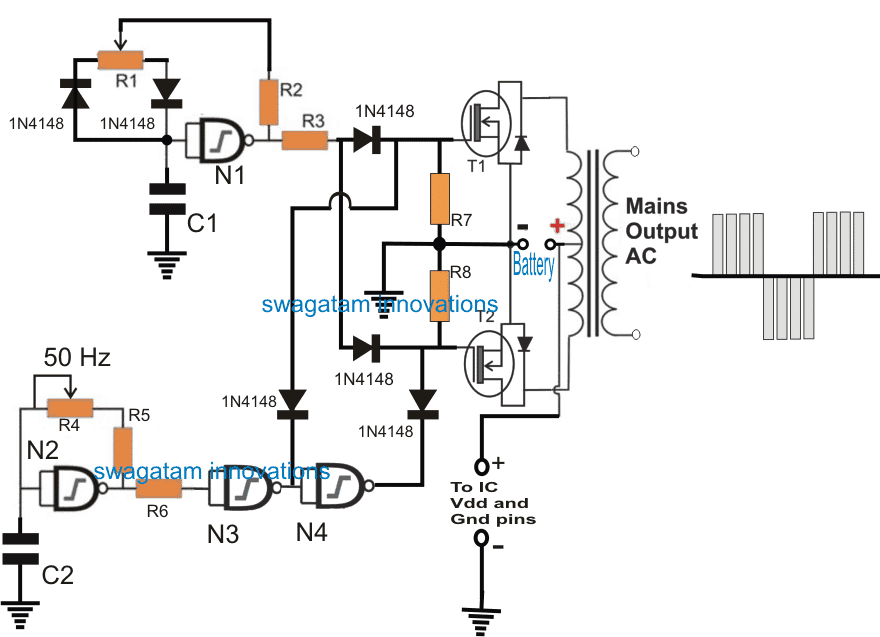
The UPS design utilizes just a single IC 4093 and yet is able to execute a good PWM modified sine wave functions at the output.
Parts List
- N1---N3 NAND gates from IC 4093
- Mosfets = IRF540
- Transformer = 9-0-9V / 10 amps / 220V or 120V
- R3/R4 = 220k pot
- C1/C2 = 0.1uF/50V
- All resistors are 1K 1/4 watt
Inverter Circuit Operation
The IC 4093 consists of 4 Schmidt type NAND gates, these gates are appropriately configured and arranged in the above shown inverter circuit, for implementing the required specifications.
One of the gates N1 is rigged as an oscillator to produce 200 Hz, while another gate N2 is wired as the second oscillator for generating 50Hz pulses.
The output from N1 is used for driving the attached mosfets at the rate of 200Hz while the the gate N2 along with the additional gates N3/N4, switches the mosfets alternately at the rate of 50Hz.
This is to ensure that the mosfets are never allowed to conduct simultaneously from the output of N1.
The outputs from N3, N4 break the 200Hz from N1 into alternate blocks of pulses which are processed by the transformer to produce a PWM AC at the intended 220V.
This concludes the inverter stage for our UPS making tutorial.
The next stage explains the changeover relay circuit, and how the above inverter needs to be wired with the changeover relays for facilitating the automatic inverter back up and battery charging operations during mains failure, and vice versa.
Relay Changeover Stage and Battery Charger Circuit
The image below shows how the transformer section of the inverter circuit may be configured with a few relays for implementing the automatic changeover for the proposed UPS design.
The figure also shows a simple automatic battery charger circuit using the IC 741 on the left side of the diagram.
First I have explained how the changeover relays are wired and then we can proceed with the battery charger explanation.
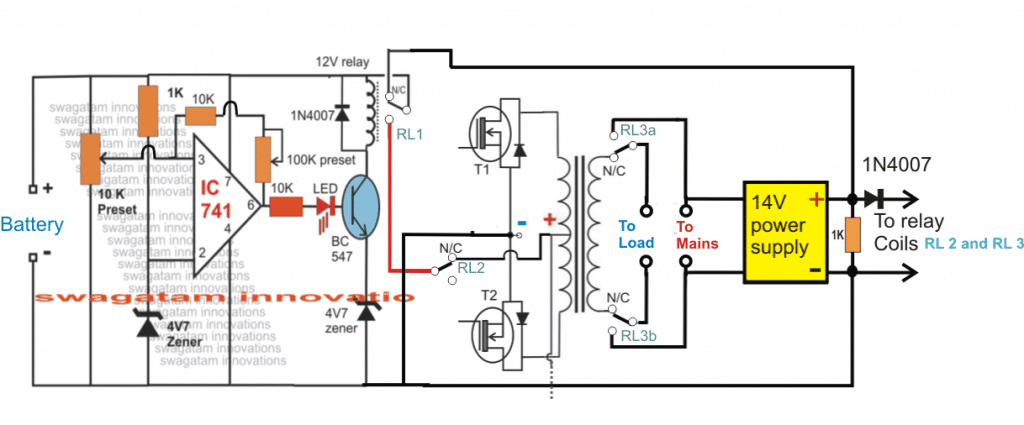
In all there are 3 sets of relays which are used in this stage:
1) 2 nos of SPDT relays in the form of RL1 and RL2
2) One DPDT relay as RL3a and RL3b.
RL1 is attached with the battery charger circuit and it controls the high/low cut charge level cut-off for the battery and determines when the battery needs is ready to be used for the inverter and when it needs to be removed.
The SPDT RL2 and the DPDT (RL3a and RL3b) are used for the instant changeover actions during a power failure and restoration. RL2 contacts are used for connecting or disconnecting the center tap of the transformer with the battery depending on the mains availability or absence.
RL3a and RLb which are the two sets of contacts of the DPDT relay become responsible for switching the load across the inverter mains or the grid mains during power outages or restoration periods.
The coils of RL2 and DPDT RL3a/RL3b are joined with a 14V power supply such that these relays quickly activate and deactivate depending on the input mains status and do the necessary changeover actions. This 14V supply is also used as the source for charging the inverter battery while the mains power is available.
The coil of the RL1 can be seen connected with the opamp circuit which controls the battery charging of the battery and ensures the supply to the battery from the 14V source is cut-off as soon as it reaches the same value.
It also makes sure that while the battery is in the inverter mode and is consumed by the load, its lower discharge level never goes below 11V, and it cuts off the battery from the inverter when it reaches around this level. Both these operations are executed by the relay RL1 in response to the opamp commands.
The setting-up procedure for the above UPS battery charger circuit can be learned from this article which discuses how to make a low high cut off battery charger using IC 741
Now it simply needs to integrate all the above stages together for executing a decent looking small UPS, which could be used for providing an uninterruptible power to your PC or any other similar gadget.
That's it, this concludes our tutorial for designing a personal UPS circuit which can be easily done by any new hobbyist by following the above detailed guide.


Comments
But isn’t the following circuit (in the link) even simpler
https://www.homemade-circuits.com/wp-content/uploads/2025/02/555-ups.jpg
That looks like an online UPS, the above article explains an offline UPS.
For a correct online UPS you can refer to the following post:
https://www.homemade-circuits.com/simple-online-ups-circuit/
You mention relays as the switchover mechanism, but do these not create a very short interruption? If so, then this is not truly uninterruptible, just a battery backup?
An appropriately rated, good quality relay changeover time will be within 10 ms which is sufficient not to have any impact on any critical appliance.
Thanks. That is valuable information. I guess the 10ms is bridged by a simple capacitor?
Sorry, I did not understand what you meant by, “I guess the 10ms is bridged by a simple capacitor?”
Even 10ms is a break in the supply — perhaps enough to cause a microprocessor to restart? I wonder however whether a largish capacitor added to the power supply might hold charge for long enough to stop the supply being interrupted — i.e. to “bridge” that 10ms gap?
My fundamental point is that there is a distinction between battery backup and uninterrupted power. I am trying to determine whether the design you propose is truly uninterrupted, or just a battery backup with a fast switchover.
My situation is that I have an alarm system, broadband router, and computers –including a home automation system that is part of the alarm system — in a house that already has a Tesla Powerwall. The Powerwall is effectively a battery backup for the whole house. It can (I gather) take 1 or 2 seconds to switch over to battery in the event of a mains power cut.
I therefore want a (truly uninterruptible) UPS for these sensitive devices — alarm system, broadband router, and computers — that will keep them operating during the switchover to Powerwall battery.
When the Powerwall battery is nearly flat, it should warn the computers in advance so they can fire off last messages and shut down gracefully.
Yes, that’s right, all electronic gadgets will have an associated filter capacitor across their supply terminals which should be able to bridge any supply interruption for at least a second.
The design explained in the above article can be considered a full-fledged UPS, or simply an offline UPS, because it will fulfill the purpose of an UPS, if the 10ms issue is not a concern to the load.
The main advantage of an offline UPS is that it allows the load to access the pure AC from the grid while the mains AC is available and also allows the inverter section to be completely switched OFF, keeping the stress level on the inverter minimal.
Nevertheless if you are interested in having a 100% seamless transition between the AC supplies then you can opt for an online UPPS, as explained in the following article:
https://www.homemade-circuits.com/simple-online-ups-circuit/
However, in your case it seems your system can work with a DC UPS, which does not require an AC inverter?
In that case the Supply transition can be absolutely seamless without any interruption at all, even for a fraction of a second.
I have a related article on this concept too, you can read it here, it can be modified as per personal preferences:
https://www.homemade-circuits.com/simple-dc-ups-circuit-for-modemrouter/
Let me know your thoughts on this.
Right on all counts! Thanks for the detailed clarification and pointers to your other interesting articles.
Yes, this one and your first reference assume that continuity of mains AC is required, and I appreciate the distinction between online snd offline.
In my case the simple DC solution should suffice. The alarm system needs 12v DC. The home automation computer needs 19V DC and the router also needs 12V DC I think. I guess your DC design drops the voltage by 0.6V due to the diodes, but should be near enough.
I want to add a battery test mode, which will temporarily shut off the input and measure the voltage, and a sensor to tell the system that it is running on the battery— probably an optocoupler on the input side.
Thanks again for the ideas!
Sure, a battery test mode can be included, by adding a series current sensing resistor with the battery positive, and then sensing the voltage drop across this resistor to indicate that battery is being used by the load. Optocoupler can be less sensitive than a transistorized sensor, so a transistor should be more preferable.
Cheers
Good day sir
Thank you for the amazing content.
Can I please ask that if I use a 6ah 12v battery is it still going to work or am I only going to have to use a 10 amp battery? My second question is what is the power output (watts)of this circuit when running on ups?
Thank you in advance.
Hi Pieter,
You can use a 6Ah battery but that will give you lower backup than a 10Ah battery.
Power will depend on the transformer rating and battery rating.
I have always follow your post. I am just a beginner and will wish you send me a functional inverter circuit that I can practice and develop and learn from your wealth of experience.
No problem, you can try the first design from this article:
https://www.homemade-circuits.com/7-simple-inverter-circuits/
hello again sir
i’m wondering about the ups system i should purchase for the oxygene concetrator system
can u help with a suggestion
thank u
Hi Zied, I am sorry, I do not have much information regarding which UPS brand would be best suitable for your application!
hi sir
i hope ur well
I’m a student working on an oxygéne concetrator that works with energy 3kw/h , u=220 v , p=1500 w
i need the circuit of its UPS circuit with its failure system
Thank you .
Hello zied, do you want an online UPS or offline UPS….I can only provide a basic design
i want offline ups
thank u very much
You will have to make or buy a 1500 watt inverter, and then integrate with it the last circuit from the following article
https://www.homemade-circuits.com/how-to-convert-inverter-to-ups/
thank u sir have a good day
You are welcome!
Hey! Thank you for your explanation.
I have a doubt about Relays.
My UPS has 4 Relays (SPDT) (2 – 4pin and 2 – 5pin) [Black outline]
1st relay (4pin) connects from Mains [Brown Square] input to another relay common.
2nd relay (5pin) outputs to two windings of the transformer [green and blue Square]
3rd relay (5pin) outputs to two windings of the transformer [green and yellow Square]
4th relay (4pin) connects from 3rd relay common to UPS output [Brown Square-bottom left]
Here are the images – https://drive.google.com/drive/folders/1Mx6_oDjlHnM-KjAIyRmf9EYQ4ut5g9Pe?usp=sharing
Numbers along the transformer input wires are – when you apply 240V between green and black you get 7.3V at the secondary, similarly for other windings.
The Black and Red square are connected to the battery and, the blue and red rectangle are connected to the secondary of the transformer.
I want to ask “How does the current flows?” “How does it charges the battery?” “How are the relay connections?”
What I know (guess),
The current flows from live wire (main) to common (relay 1) to Normally open (relay 1) to common (relay 2) to normally closed (relay 2) to normally closed (relay 3) to common (relay 3) to common (relay 4) to normally open (relay 4) to UPS output.
I made a block diagram also.
“Why are there different connections to different windings?”
Hi, It is extremely difficult to figure out the wiring and the functioning of the relay just by referring to the images your provided…I will need schematic diagram to actually know how the system is configured and its working.
Hi Sir,
Could you pls post circuit for 2 to 5KW UPS.
Thank and Regards
Uday Joshi
Uday, please build a smaller version first, may be a 100 watt design, if you succeed then you can easily upgrade it to any desired higher level….
Yes , I thing you are right. Any link for 100 watt??
Regards
Uday
You can try the concept explained in the above post, if everything goes well, you can upgrade it to higher levels.
Hi Swagatam,
I am looking to make a simple DC-DC UPS for my modem. I found this solution on instructables – however the flaw in the design is that if mains goes off when battery is discharged, it will fail to supply power. This design does not have a relay in it.
Can you help me with similar component selection – however by adding a relay that allows fallback on battery ONLY when mains go off. I would like to use below set of parts for this design –
1. DC DC Boost – MT3608
2. LiIon Charger – TP4056
Let me know if I need to go for different components. Appreciate your help and response.
~Prashant
You can build the same without a relay as shown below:
Really appreciate the inputs!!! And prompt response. Will build both of them and get back with final product feedback. Thanks!
~Prashant
No Problem!
Hi Prashant, Please see the following image, I hope this may fulfill your requirement:
Thanks again for such a useful UPS post in a need full time. I just have few question though,
1. Since I will be using a 9v-0-9v / 220 Trafo , is it advisable to wind another auxiliary 14V for charging purpose avoiding using external adapter .
2.Considering the availability and cost of high freaquency Ferrite Trafo, can the charger and change over switch be integrated to high freaquency smps inverter
I will appreciate your assistance
Glad you liked the post, I’ll try to help you:
1) you can have an auxiliary winding, no problem, although using an external adapter appears to be an easier and hassle free option.
2) If the SMPS also employs the same center tap MOSFET topology then the above system can e applied in it for getting the same results.
Hello sir swagatam, please if you don’t mind help me a circuitry for 24v system. Most circuits you use are 12v based, please help. Also sir we can as well make use of the internal mosfet diodes instead of the tedious work of looking for a separate power supply for charging battery coz getting a high current rl3 say for a 6000w ups is much expensive. Do you have any I deal about this?
I like the circuit, but what are the values of the Resistances?
resistors are all 1K
Hi sir.can i know the simulation of offline uninterruptible power supply(UPS) on the MATLAB Simulink and how can i know the system can works as backup power supply when the main supply is powered off from the simulation? Then, what can i do for the improvement harmonic distortion on UPS as the the system is already designed to mitigate distortion? I hope ur can help me. Thanks in advanced !
Hi Mara, you can verify the design by testing it practically and you will find it working with 100% results (if done correctly). I do not have any simulation results for my circuits.
Dear sir,
The above circuit works with 12 V DC battery, i assume. What should be the current rating of the battery. It is mentioned that refrigerator will work. What is the maximum load(s) that can be connected with the above circuit. If i want to increase the loads, say double the load what modifcation is to be done? Thanks and regards.
Dear Premila,
You can upgrade the inverter wattage as per your requirement. You just have to use a transformer that matches the specs of the load, similarly use a battery as per the transformer and the load…and the mosfets which can handle the trafo and battery current confortably, only these 3 parameters should be matched for ensuring the required output wattage.
Thanks for the tip, and keep on the good work Sir.
you are welcome Tun
Hi, Mr Swagatam, I do really like to ask you these question that seem to be bothering for a long time. It all about modifying a 650va UPS (introducing two way power source e.g both battery and solar panels), besides, I need to know the suitable nos(watt ratting) for panels. Thank you
Hi Tun, please refer to the following article for solving your doubts
https://www.homemade-circuits.com/2013/05/how-to-calculate-and-match-solar-panel.html
Hi, mr.swagatam, I need your help, I have transformer from old ups, I want to built inverter 12vcd to 220vac used this transformer, but the transformer not have center tap, how can I used,, thanks for help..
Hi Christian, without a center tap you may have to employ a full bridge inverter topology, as shown below
https://www.homemade-circuits.com/2014/01/simplest-full-bridge-inverter-circuit.html
son muy bienvenidos a Jesús, agradezco su interés