The following 5 versions of 6 volt 4 AH battery charger circuits has been designed by me and posted here in response to the request from Mr. Raja, I have explained the whole conversation.
Technical Specifications
"Dear sir, please post a circuit to charge 6 volt 3.5 ah lead acid battery from 12 volt battery. The charger should automatically stop charging as the battery is fully charged.
Please use transistor instead of relay to stop charging, and also tell me how to use 12 volt relay for the same circuit.
Explain Which is safe and durable either relay or transistor to cut off charging. (At present i am charging my above said battery by simply using LM317 with 220 ohm and 1 kilo ohm resistors and a couple of capacitor) i'm awaiting your article, thank you".
The Design
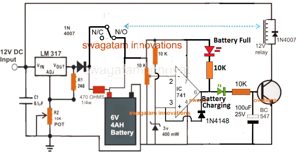
The following circuit shows a simple automatic 6 volt 4 to 10 AH battery charger circuit using a 12 volt relay, designed to automatically cut off the supply to the battery as soon as the full charge level for the battery is reached.
How it Works
Assuming no battery is connected with the circuit, when power is switched ON, the relay contact will be at the N/C and no power will be able to reach the IC 741 circuit.
Now when battery is connected, the supply from the battery will actuate the circuit, and assuming the battery to be in a discharged state, pin#2 will be lower than pin#3 causing a high at pin#6 of the IC. This will switch ON the transistor relay driver, which in turn will shift the relay contact from N/C to N/O connecting the charging supply with the battery.
The battery will now begin charging slowly and as soon a its terminals reaches at 7V, pin#2 will tend to become higher than pin#3, causing pin#6 of the IC to become low, switching OFF the relay and cutting off supply to the battery.
The existing low at pin#6 will also cause pin#3 to become permanently low through the linked 1N4148 diode, and thus the system will be latched, until power is switched OFF and ON again.
If you don't wish to have this latching arrangement, you can very well eliminate the 1N4148 feedback diode.
Note: The LED indicator section for all 3 following diagrams were recently modified after a practical testing and confirmation
Circuit#1
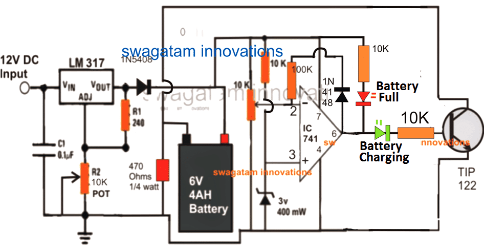
The following circuit shows a simple automatic 6 volt 4 AH battery charger circuit without using a relay, rather directly through a transistor, you can replace the BJT with a mosfet also to enable high Ah level charging also.
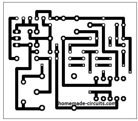
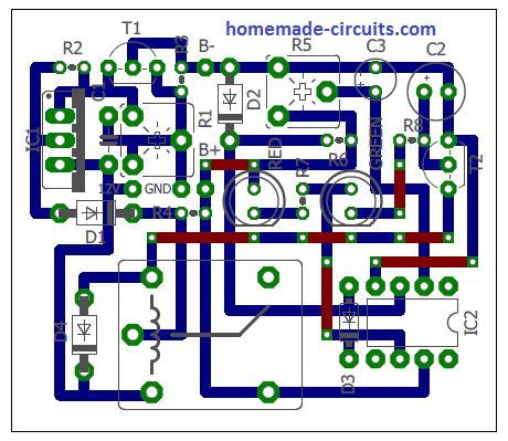
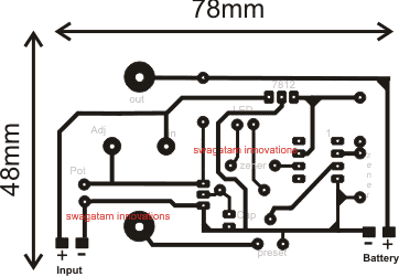
PCB Design for the Above Circuit
The PCB layout design were contributed by one of the avid followers of this website, Mr. Jack009
Circuit#2
Update:
The above transistorized 6V charger circuit has a mistake. At the full-charge level as soon as the battery negative is cut-off by the TIP122, this negative from the battery is also cut-off for the IC 741 circuit.
This implies that now the IC 741 is unable to monitor the discharging process of the battery, and will be unable to restore the battery charging when the battery reaches the lower discharge threshold?
To correct this we need to make sure that at the full-charge level, the battery negative is only cut-off from the supply line, and not from the IC 741 circuit line.
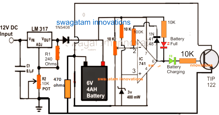
The following circuit corrects this flaw and makes sure that the IC741 is able to monitor and keep track of the battery health continuously under all circumstances.
How to Set Up the Circuit
Initially, keep the pin6 feedback resistor disconnected and without connecting any battery adjust R2 to get exactly 7.2V at the output of the LM317 (across cathode of 1N5408 and ground line), for powering the IC 741 circuit.
Now simply play with the 10k preset and identify a position where the RED/GREEN LEDs just flip/flop or change or swap between their illumination.
This position within the preset adjustment may be considered as the cut-off or the threshold point.
Carefully adjust it to a point at which the RED LED in the first circuit just lights up......but for the second circuit it should be the green LED that is supposed to get illuminated.
The cut-off point is now set for the circuit, seal the preset in this position and reconnect the pin6 resistor across the shown points.
Your circuit is now set for charging any 6V 4 AH battery or other similar batteries with an automatic cut-off feature as soon as or each time the battery becomes fully charged at the above set 7.2V.
Both the above circuits will perform equally well, however the upper circuit can be altered to handle high currents even up to 100 and 200 AH just by modifying the IC and the relay. The lower circuit may be made to do this only up to a certain limit, may be up to 30 A or so.
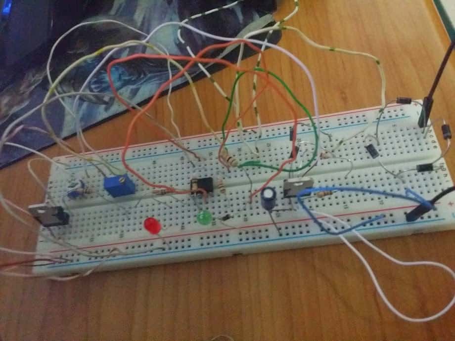
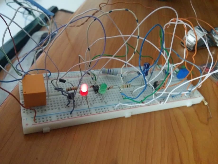
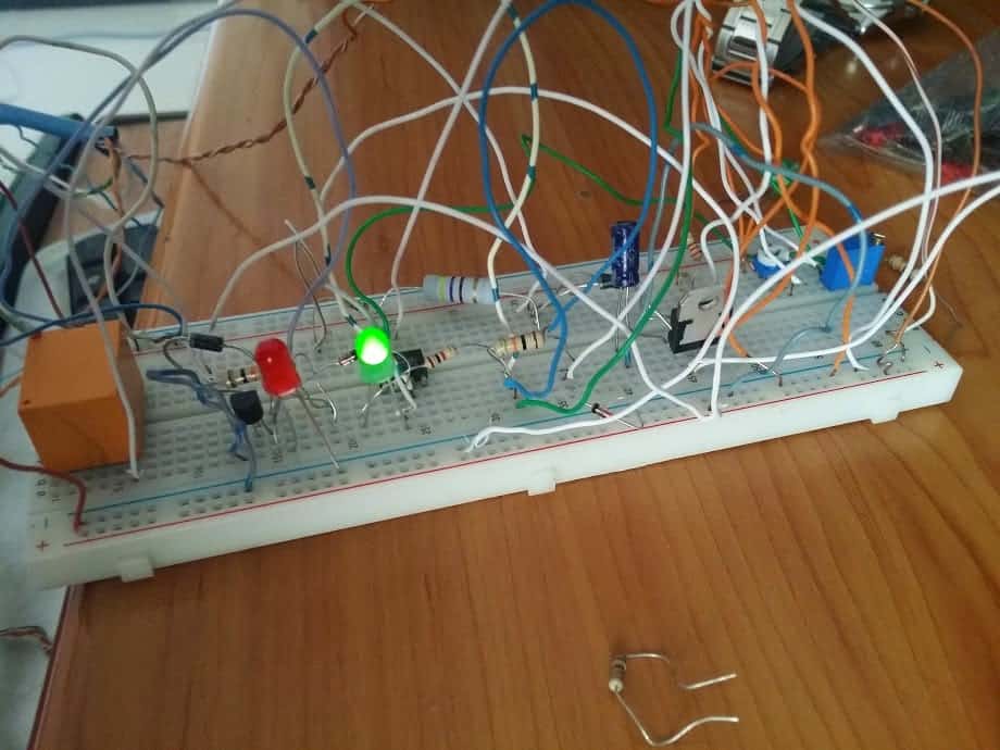
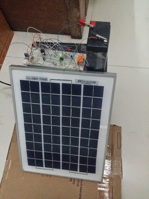
The second circuit from above was successfully built and tested by Dipto who is an avid reader of this blog, the submitted images of the 6V solar charger prototype can be witnessed below:
Adding a Current Control:
An automatic current control regulator function can be added with the above shown designs by simply introducing a BC547 circuit as shown in the following diagram:
Circuit#3
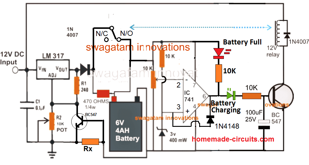
The current sensing resistor can be calculated through the simple Ohm's law formula:
Rx = 0.6 / Max charging current
Here 0.6V refers to the triggering voltage of the left side BC547 transistor while max charging current signifies the maximum safe charging for the battery, which may be 400mA for a 4AH lead acid battery.
Therefore solving the above formula gives us:
Rx = 0.6 / 0.4 = 1.5 Ohms.
Watts = 0.6 x 0.4 = 0.24 watts or 1/4 watt
By adding this resistor will ensure that the charging rate is fully controlled and it is never exceeded the specified safe charging current limit.
Test Report Video Clip:
The following video clip shows the testing of the above automatic charger circuit in real time. Since I did not have a 6V battery, I tested the design on a 12V battery, which does not make any difference, and its all about setting the preset accordingly for the 6V or a 12V battery as per user preference. The above shown circuit configuration was not changed in any manner.
The circuit was set to cut off at 13.46V, which was selected as the full charge cut off level. This was done to save time because the actual recommended value of 14.3V could have taken lot of time, therefore to make it quickly I selected 13.46V as the high cut off threshold.
However one point to be noted is that the feedback resistor was not employed here, and the lower threshold activation was automatically implemented at 12.77V by the circuit, as per the IC 741's natural hysteresis property.
6V Charger Design#2
Here's another simple yet accurate automatic, regulated 6V lead acid battery charger circuit which switches off the current to the battery as soon as the battery reaches full charge. An illuminated LED at the output indicates the fully charged condition of the battery.
How it Works
The CIRCUIT DIAGRAM can be understood with the the following points:
Fundamentally the voltage control and regulation is done by the versatile, work horse IC LM 338.
An input DC supply volt in the range of 30 is applied to the input of the IC. The voltage may be derived from a transformer, bridge and capacitor network.
The value of R2 is set to get the required output voltage, depending upon the battery voltage to be charged.
If a 6 volt battery needs to charged, R2 is selected to produce a voltage of around 7 volts at the output, for a 12 volt battery it becomes 14 volts and for a 24 volt battery, the setting is done at around 28 volts.
The above settings take care of the voltage that needs to be applied to the battery under charge, however the tripping voltage or the voltage at which the circuit should cut off is set by adjusting the 10 K pot or preset.
The 10K preset is associated with the circuit involving the IC 741 which is basically configured as a comparator.
The inverting input of the IC 741 is clamped at a fixed reference voltage of 6 via a 10K resistor.
With reference to this voltage the tripping point is set via the 10 K preset connected across the non inverting input of the IC.
The output supply from the IC LM 338 goes to the battery positive for charging it. This voltage also acts as the sensing as well as the operating voltage for the IC 741.
As per the setting of the 10 K preset when the battery voltage during the charging process reaches or crosses the threshold, the output of the IC 741 goes high.
The voltage passes through the LED and reaches the base of the transistor which in turn conducts and switches off the IC LM 338.
The supply to the battery is immediately cut off.
The illuminated LED indicates the charged condition of the connected battery.
Circuit#4
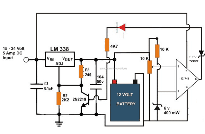
This automatic battery charger circuit can be used for charging all lead acid or SMF batteries having voltages in between 3 and 24 volts.
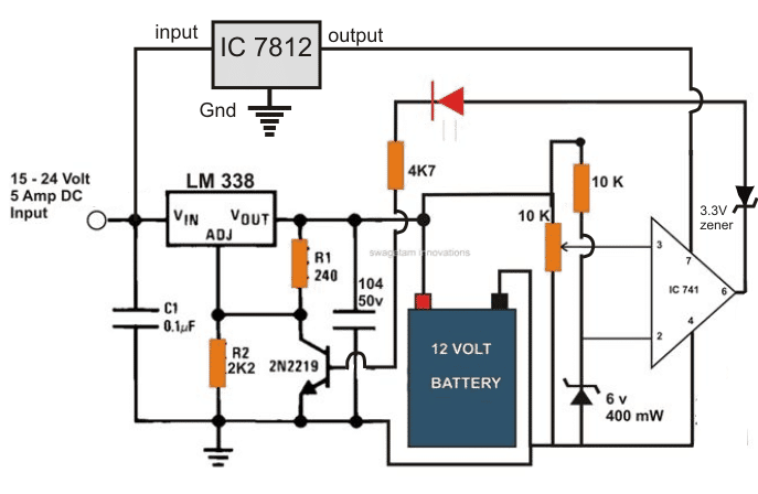
The above circuit was found not so satisfactory by some of the readers, so I have modified the above circuit for a better and guaranteed functioning. Kindly see the modified design in the below given figure.
PCB Design for the above finalized 6V, 12V, 24V automatic battery charger circuit
Solar 6V Battery Charger Circuit with Over Current Protection
So far I have explained how to a simple 6V battery charger circuit with over current protection using mains input. In the following discussion I will try to explain how the same could be configured in conjunction with a solar panel, and also with an AC/DC adapter input.
The circuit also includes a 4 stage battery status indication feature, an over current controller stage, automatic switch OFF for the load and battery charging, and also a separate cell phone charging outlet. The idea was requested by Mr. Bhushan Trivedi.
Technical Specifications
Greetings, I trust you are well. I am Bhushan, and I am working on a hobby project currently. I am very impressed by the knowledge you share at your blog, and was hoping if you would like to guide me a bit with my project.
My project is around charging a 6V 4.5 Ah sealed battery with grid and solar panel.
This battery will supply power to led lights and a mobile phone charging point. Actually, the battery will be kept in a box. and box will have two inputs for battery charging. These two inputs are solar (9V) and AC (230V) for charging the 6V Battery.
There will not be any automatic switchover. Its like the user has an an option to either charge the battery from solar or grid. but both the input options shall be available.
For example, if on a rainy day or for some reason the battery can't be charged from a solar panel, then grid charging should be done.
So I am looking for an option of both the inputs to the battery. Nothing automatic hereThe battery level indicator LED should indicate in red yellow and green on the battery level.
Automatic battery cut off after voltage goes down certain limits to ensure long battery life. I am attaching a short problem statement along this email for your reference.
I am looking for a circuit for the arrangement shown in it. I am keen to hear from you on this
Kind Regards,
Bhushan
The 5th Design
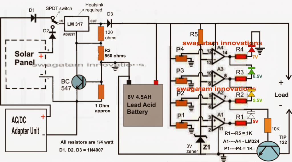
The required 6V solar battery charger circuit can be witnessed in the diagram presented below.
Referring to the diagram, the various stages may be understood with the help of the following points:
The IC LM317 which is a standard voltage regulator IC is configured to produce a fixed 7V output determined by the resistances 120 ohms and 560 ohms.
The BC547 transistor and its base 1 ohm resistor ensure that the charging current to the 6V/4.5AH battery never exceeds the optimal 500mA mark.
The output of the LM317 stage is directly connected with the 6V battery for the intended charging of the battery.
The input to this IC is selectable via a SPDT switch, either from the given solar panel or from an AC/DC adapter unit, depending whether the solar panel is producing sufficient voltage or not, which could be monitored through a voltmeter connected across the output pins of the LM317 IC.
The four opamps from the IC LM324 which is a quad opamp in one package are wired up as voltage comparators and produce a visual indications for the various voltage levels at any instant, during the charging process or during the discharging process through the connected LEd panel or any other load.
All the inverting inputs of the opamps are clamped to a fixed reference of 3V through the relevant zener diode.
The non-inverting inputs of the opamps are individually attached to presets which are appropriately set to respond to the relevant voltage levels by making their outputs high sequentially.
The indications for the same could be monitored via the connected colored LEDs.
The yellow LED associated with A2 may be set for indicating the low voltage cut-off threshold. When this LED shuts off (white lights up), the transistor TIP122 is inhibited from conducting and cuts off the supply to the load, thereby ensuring that the battery is never allowed to discharge to dangerous unrecoverable limits.
A4 LED indicates the upper full charge level of the battery....this output could be fed to the base of the LM317 transistor in order to cut-off the charging voltage to the battery preventing overcharging (optional).
Please note that since the A2/A4 do not have hysteresis included could produce oscillations at the cut-off thresholds, which won't necessarily be an issue or affect the battery performance or life.
Circuit#5
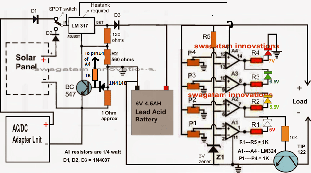
Adding an Auto-cut OFF on Batery Battery Full Charge
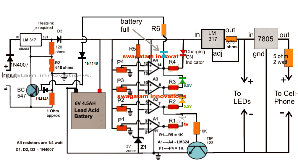
The modified diagram with over charge auto-cut of can be implemented by connecting A4 output with the BC547.
But now the current limiting resistor formula will be as follows:
R = 0.6 + 0.6 / max charge current
Feedback from Mr. Bhushan
Thank you very much for your continued support and the above circuit designs.
I have a few minor changes to the design now, which I would like to request you for incorporating in the circuit design. I would like to express that cost of the PCB and components is a big concern, but I do understand quality is also very important.
Hence, I request you to strike a fine balance between the performance and cost of this circuit. So to begin with, we have this BOX, in which will house the 6V 4.5 Ah SMF Lead Acid Battery and the PCB too.
The 6V 4.5 Ah Battery will be charged either through the followingn options from one single input:
a) A 230 V AC to 9V DC Adaptor (I wish to go ahead with a 1 amp rating charger, your views?) ‘OR’
b) A 3-5 Watt Solar module (Max Voltage: 9 V (6V nominal), Max Current: 0.4 to 0.5 Amps)
Block Diagram
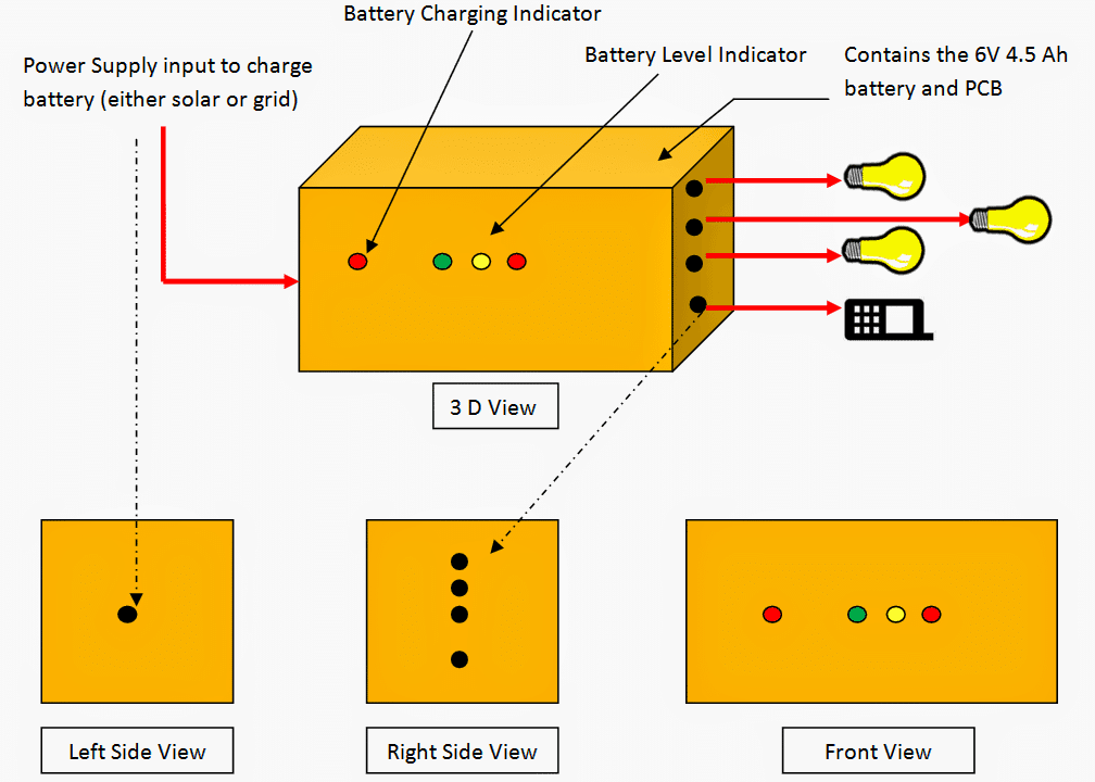
The battery can be charged by only one supply at a time hence will only have one input on the left side of the box.
For the time when this battery is being charged, there will be small red led light which glows on the font face of the box (Battery Charging Indicator in diagram) Now, at this point, the system should also have a battery level indicator (Battery level Indicator in diagram)
I wish to have three levels of indications for the battery state. These tables state the open circuit voltage. Now with the very little electronic knowledge I have, I am assuming this is ideal voltage and not the actual conditions, right?
I think I will leave that on you to decide and use any correction factors if required for calculations.
I wish to have the following indicator levels:
- Charge level 100% to 65% = Small Green LED is ON (Yellow and Red LED off)
- Charge level 40% to 65% = Small Yellow LED is ON (Green and Red LED off)
- Charge level 20% to 40% = Small Red LED is ON (Green and Yellow LED off)
- At 20% Charge level, battery disconnects and stops supplying output power.
On the Output side now (Right Side View in diagram)
The system will supply power to the following applications:
a) 1 Watt, 6V DC LED Bulb – 3 No’s
b) One output for Mobile Phone Charging I wish to incorporate a feature here. As you see, the DC loads connected to the battery are of relatively less wattage. (just a mobile phone and three 1 watt LED Bulbs). Now, the feature to be added in the circuit should kind of work as a fuse ( I don’t mean an actual fuse here).
Assume if a CFL bulb is connected here or some other application of higher wattage rating, power supply should be cut off. If the total power drawn is in excess of 7.5 Watts DC connected to this system, the system should cut off supply and shall only resume when the load is below 7.5 Watts.
I basically wish to ensure that this system is not misused or drawn excessive energy from, thereby damaging the battery.
This is just an idea. I do however understand this can potentially increase the complexity and cost of the circuit. I will look for your recommendation on this on whether to include this feature or no as we already are cutting off the battery supply once the state of charge reaches 20%.
I hope you find this project exciting to work on. I look forward to receiving your much valued inputs on this.
I am thanking you for all your help till now and in advance for your extended cooperation on this.
Kind Regards,
Bhushan.
The Design
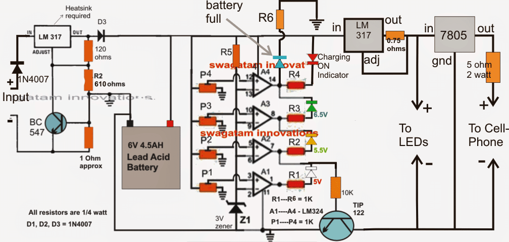
Here's a brief explanation of the various stages included in the proposed 6V battery charger circuit with over current protection:
The left side LM317 is responsible for producing a fixed 7.6V charging voltage across its output pin and ground for the battery, which drops to around 7V via D3 to become an optimal level for the battery.
This voltage is determined by the associated 610 ohm resistor, this value can be reduced or increased for changing the output voltage proportionately if required.
The associated 1 ohm resistor and the BC547 restricts the charging current to around a safe 600mA for the battery.
The opamps A1---A4 are all identical and perform the function of voltage comparators. As per the rules if the voltage at their pin3 exceeds the level at pin2, the corresponding outputs become high or at the supply level..... and vice versa.
The associated presets may be set for enabling the opamps to sense any desired level at their pin3 and make their corresponding outputs go high (as explained above), thus A1 preset is set such that its output becomes high at 5V (Charge level 20% to 40%)....A2 preset is set to respond with an output high at 5.5V (Charge level 40% to 65%), while A3 triggers with a high output at 6.5V (80%), and finally A4 alarms the owner with the blue LED at battery level reaching the 7.2V mark (100% charged).
At this point the input power will need to be switched off manually since you did not demand for an automatic action.
Once the input is switched off, the 6v battery level sustains the above positions for the opamps, while the output from A2 ensures that the TIP122 conducts keeping the relevant loads connected with the battery and operative.
The LM317 stage at the right is a current controller stage which has been rigged to restrict the output amp consumption to 1.2 amps or around 7 watts as per the requirements. The 0.75 ohm resistor may be varied for altering the restriction levels.
The next 7805 IC stage is a separate inclusion which generates a suitable voltage/current level for charging standard cell phones.
Now, as power is consumed the battery level begins receding in the opposite direction, which are indicated by the relevant LEDs....
Blue is the first one to shut off illuminating the green LEd, which shuts off off below 6.5V illuminating the yellow LEd which identically shuts off at 5.9V making sure that now the TIP122 no longer conducts and the loads are shut off....
But here the condition may oscillate for some moment until the voltage finally reaches below 5.5V illuminating the white LEd and alarming the user for an input power switch on and commence the charging procedure.
The above concept can be further improved by adding an automatic full charge cut off facility, as shown below:


Questions & Answers
Dear Sir,
As per your instruction I have repeat the
previews adjustment, first adjust 2K2 POT
for required output charging voltage & swap
the 10k variable resistor with successfully
Green LED on and shut off red but not fully
off with slide lighting . but could not
charging when connect negative voltage from
TIP 122 (Collector). after input negative
voltage connect to battery terminal & it
charging to battery with heat to LM 317.
please help me to find-out the problems.
for your information I have attached picture
file of circuit.
1. How to off & on TIP 122 transistor with
which voltage need to done this job?
2. please explain the function of base
Zaner diode of TIP 122 transistor?
Below the voltage status of circuit
Input voltage 11.94 with 5A
output regulated voltage 7.77 after adjusting the 2.2k variable.
IC PIN 2 voltage =7.77
IC pin 3 voltage =7.08
IC pin 6 voltage =2.17 after swap the 10k
variable & before swap 10kV voltage was V6.74
TIP122 Base voltage after swap 10k variable
140 mV and 0.657V before swap the 10k
Variable.
Thanks & Regards
Tanvir Ahmed
Bangladesh
facebook.com/cse.tanvir
Dear Tanvir,
You have done just the opposite of what was required to be done.
Without connecting any battery, set the 2k2 pot for the required output, next adjust the 10k preset to just switch ON the RED LED.
After this switch off the circuit, connect the battery, and switch ON power. Now you will find red LED switched OFF and the green LED coming ON…once the battery gets fully charged, the RED will again switch ON indicating that the battery is charged and disconnected.
While setting 10K preset remember to disconnect the 100k feed back resistor….connect it back after the setting is done.
….the input current must be rated at 1/10th of the battery AH, otherwise the above procedures will not work.
I'm awaiting your helpful feedback.
Hi,
I am sure this circuit is very good. But I need your help here. This circuit is for 6v 4ah battery but I have 6v 4.5ah (1) battery. and I also have 4v 3ah (1) and 3v 2ah (1) total 3 batteries that I bought few days ago.
Please help me build charger for the battery 6v 4.5ah battery. and also please tell me can I use Nokia charger (5v 350 ma) for two of my other batteries directly to charge?
I will be very happy if you help me.
Regards,
MD
Hi,
You can use the above circuit for charging all the three batteries that you have bought by suitably adjusting the given presets in the circuit.
You can use the 5v charger supply with the above explained circuit for charging the 3V batteries.
Thank you very much for you very useful information. But can you please tell me which circuit should I built for my case ? the first one or the second one ?
And Kindly please tell me which presets I should change to charge 3v & 4v batteries ?
I understand that I can use the Nokia charger to power the circuit to charge the 3v & 4v batteries, but in this case I need any parts change on the circuit ?
Waiting for your information.
B. Regards,
MD
You can try the second circuit.
No change in parts would be required.
Ideally it should 7V @500mA
1) It's due to parasitic leakage from the IC output, it can be corrected in the following manner.
Swap the positions of the transistor base resistor and the zener, next shift the LED joint in between the resistor and the zener, this will clean up the issue.
2)The relay contacts can be seen connected with the battery positive, so as soon as it activates the battery gets disconnected from the supply at the full charge conditions.
try using a boost charger circuit as shown in article:
https://www.homemade-circuits.com/2013/03/how-to-convert-12v-dc-to-220v-ac-using.html
the coil will need to be modified appropriately.
It means your opamp is faulty or there's some other kind of mistake, because altering the 10K preset should certainly make the relay flip.
I think it would be better if you refer and learn how an opamp functions, it will help you to troubleshoot the issue immediately from the core. there are many online sources dealing with this subject
By the way did you remove the feed back 10k resistor while doing the testing, it is important otherwise the relay will not respond properly.
The relay N/C contact connects with the diodes, diode should be a rectifier diode rated at least at 1amp, any type will do.
yes it will.
Don't modify the cell phone charger, use a power supply with an output of at least 7V and current 1 Amp.
you can use a 12v/750mA trafo…
…use a bridge rectifier and a 2200uF/25V for the filtering the DC.
hey dear nice circuit but im not understand 10k pot use? or not
it's for adjusting the over charge cut-of threshold level of the battery
sir i wnt 2 make a solar chrge controler of 6v nd 5amp which circuirt should i use it plz let m guide it???
hello sir,
what modification should be made in the circuit if 3v zener is replaced with 3.3v zener.
hello Seelamsetti,
no modifications would be required, you can use any zener between 3 and 9V.
see the black dot….it means it connects the LEDs links and also pin6 together
Sir
I am interested to make a battery charger for 12 volt battery.But when I went shops to get parts they could not understand relay for 12 volt battery charging.What specifications like any series number should i tell so that I can get it
Thanking you
P Ramamurthi
Hello Ramamurthi,
please tell them to give you a 12V, 10amp relay, preferably a PCB mount type and made by O/E/N.
hello, i tested the ckt some month ago. after that i was an accident and do not finished. now i again test. but something is wrong. when i switch on the power of ur ckt my relay is energized and green led is lit. i bought new 6V 4.5A battery and connect to the ckt. but my battery do not charge. plz give some advice to me. i use 3.3v 1w zener diode.
Without any battery connected the input voltage should be 7V, at this voltage first adjust the 10k preset such that the relay just cut-off or deactivates.
Once this is done, then connect the battery and switch ON power, now the relay will not activate until the battery is charged.
While adjusting the 10k preset remember to keep the pin6 10k resistor disconnected…..connect it back after the adjustment is finished.
yes will do!
please clear the confusion, 2nd design tip122 transistor emiter and collector are joined to 470R resistor with ground,i think collector should go to positive. what is the purpose to use 3v zener at the base of tip122?
if i want to use 2nd circuit to charge cellphone battery (3.7v,800mah) with USB power source, what modification should be done?
the TIP122 connection is correct, rest assured.
It will be difficult to explain all the modifications for a USB 3.7 charger, because there are many changes to be done.
I'll post the compete design in my blog and provide you with the link soon.
Can you please show me the exact link of the emergency light, I will try to figure out the whole design
Hi
I want 9v input instead of 12 v what changes i need pls help
you can use the same circuit for 9V input, no changes would be required.
Dada,
If we use LM324 in place of IC741 and 4.7V Zener then do we have to change any components in the 2nd Circuit.
Tanmoy, no changes would be required if a LM324 is used, you can use the same configuration.
Hello Swagatham thanks for your help, I believe i can use the same for charging 12V battery. with suitable corrections of resistors?? Thanks for your great help
Regards
Yeshwanth kumar J
Yes surely you can do that Yashwanth….you are welcome.
Is that r 470 and two diodes connect with + battery? And if relay cut off they still connect?
Hello sir, is the 2 IN4007 and r470 connect to + batt? And if relay cut off they still connect?
Hello Sumantri,
yes, it's to keep the battery trickle charged even after cut-off.
you can eliminate the 470 ohms if you don't want this to happen.
Dear sir
I have 6v 4a battery which I use for a toy car
problem is the adapter broken and I got a adapter 6v1
Will it work?
Dear Mashal, it should be at least 6.5 to 7V for charging a 6V battery, 6.1 will not be good.
Thanks so much, you are indeed angel sent from heaven to solve human electronic hobbyist problem, more grease to your elbow.
Sir , am having problem getting TIP122 pls can I replace it with BC or mosfet? If yes which BC or mosfet can I use? Thanks in advance
thanks kolley,
what's BC?
you can try a mosfet, the specs will depend on the battery AH rating…
Thank you so much for this great circuit, I always like to build your circuit.
Pls am having problem here getting TIP 122 pls can I use BC transistor or Mosfet instead of TIP122, if yes which BC or mosfet can I use?
Thanks so much
thanks kolley,
BC series will not work….
you can try a mosfet, the specs will depend on the battery AH rating…
Sir swatagam,
what are the modification to be done i the circuit to charge a 12vdc 100ah deep cycle battery?
Joevil, you can make use of the first circuit, upgrade the relay to handle 10amps and also replace LM317 with LM396…that's all.
Sir,I need to charge a 11.1 volt 2200 mah lion battery, i have read your above reviews and understand that i will have to use a 14-15 vdc source. I am not too sure about the Current rating of the dc source, should be be around 250 ma(1/10 of the mah) or how much more? as there would be current draw from the circuit itself. thanks and warm regards
you can try a readymade 12V smps 1amp adapter, and regulate the output using an LM317 circuit…that would be much clean and easy.
use a good heatsink for the LM317
Hello sir, i have two questions,
1) Can I use a 10w 6v solar panel to charge this battery? If so what would be the current rating?
2) Can this battery charger be combined with this circuit mentioned in the link below?
https://www.homemade-circuits.com/2012/09/automatic-inverter-supply-and-mains.html