• Skip to main content
  • Skip to primary sidebar

Homemade Circuit Projects

Need circuit help? Post them in the comments! I've answered over 50,000!

Blog | Categories | About | Hire Me | Contact | Calculators-online
You are here: Home / Inverter Circuits / IR2111 H-Bridge Inverter Circuit with Soft Start


IR2111 H-Bridge Inverter Circuit with Soft Start

Last Updated on September 14, 2025 by Swagatam 4 Comments

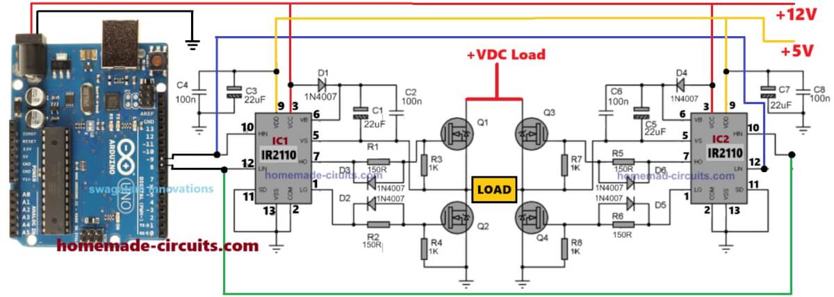
Here we see this circuit diagram which is full H-Bridge using 4 power MOSFETs and 2 IR2111 high side driver ICs.

Table of Contents
  • Power Supply Part
  • Arduino Code
  • Arduino Control Signals
  • How MOSFET Switching Happens
    • Soft Start Feature Importance

That means this circuit is for making full bridge inverter which converts DC into AC.

Power Supply Part

We have +600V DC at top rail, written as +600V max.

And ground (0V) at bottom.

Then load is connected between middle points of the bridge.

IR2111 Driver ICs

Each IR2111 has two important outputs:

HO (High Side Output)

LO (Low Side Output)

HO is used to drive upper MOSFET in each half bridge.

LO is used to drive lower MOSFET in each half bridge.

We apply +12V to Vcc pin of IR2111 for its internal power.

Also BA159 diode is used to charge bootstrap capacitor, because high side MOSFET needs voltage higher than +600V to turn fully ON.

So BA159 + 10uF bootstrap capacitor charges when low side is ON, then gives proper voltage to high side driver.

Arduino Code

// By Swagatam - Full Bridge Sine Wave Inverter Code with Soft Start Feature

const int pin1 = 8;
const int pin2 = 9;

const int softStartSteps = 100;   // Number of steps in soft start
const int softStartDelayIncrement = 20; // Microseconds increment per step

void setup() {
    pinMode(pin1, OUTPUT);
    pinMode(pin2, OUTPUT);
    
    delay(3000); // Booting delay (wait for 3 seconds before starting)
}

void loop() {
    // Perform soft start gradually
    for (int step = 0; step < softStartSteps; step++) {
        int delayAdjust = step * softStartDelayIncrement;

        runCycle(delayAdjust);
    }

    // After soft start, run normal cycle indefinitely
    while (true) {
        runCycle(softStartSteps * softStartDelayIncrement);
    }
}

// Function to run one inverter cycle with given delay adjustment
void runCycle(int delayAdjust) {
    // First pin (pin1) switching pattern
    digitalWrite(pin1, HIGH);
    delayMicroseconds(500 + delayAdjust);
    digitalWrite(pin1, LOW);
    delayMicroseconds(500 + delayAdjust);
    digitalWrite(pin1, HIGH);
    delayMicroseconds(750 + delayAdjust);
    digitalWrite(pin1, LOW);
    delayMicroseconds(500 + delayAdjust);
    digitalWrite(pin1, HIGH);
    delayMicroseconds(1250 + delayAdjust);
    digitalWrite(pin1, LOW);
    delayMicroseconds(500 + delayAdjust);
    digitalWrite(pin1, HIGH);
    delayMicroseconds(2000 + delayAdjust);
    digitalWrite(pin1, LOW);
    delayMicroseconds(500 + delayAdjust);
    digitalWrite(pin1, HIGH);
    delayMicroseconds(1250 + delayAdjust);
    digitalWrite(pin1, LOW);
    delayMicroseconds(500 + delayAdjust);
    digitalWrite(pin1, HIGH);
    delayMicroseconds(750 + delayAdjust);
    digitalWrite(pin1, LOW);
    delayMicroseconds(500 + delayAdjust);
    digitalWrite(pin1, HIGH);
    delayMicroseconds(500 + delayAdjust);
    digitalWrite(pin1, LOW);

    // Second pin (pin2) switching pattern
    digitalWrite(pin2, HIGH);
    delayMicroseconds(500 + delayAdjust);
    digitalWrite(pin2, LOW);
    delayMicroseconds(500 + delayAdjust);
    digitalWrite(pin2, HIGH);
    delayMicroseconds(750 + delayAdjust);
    digitalWrite(pin2, LOW);
    delayMicroseconds(500 + delayAdjust);
    digitalWrite(pin2, HIGH);
    delayMicroseconds(1250 + delayAdjust);
    digitalWrite(pin2, LOW);
    delayMicroseconds(500 + delayAdjust);
    digitalWrite(pin2, HIGH);
    delayMicroseconds(2000 + delayAdjust);
    digitalWrite(pin2, LOW);
    delayMicroseconds(500 + delayAdjust);
    digitalWrite(pin2, HIGH);
    delayMicroseconds(1250 + delayAdjust);
    digitalWrite(pin2, LOW);
    delayMicroseconds(500 + delayAdjust);
    digitalWrite(pin2, HIGH);
    delayMicroseconds(750 + delayAdjust);
    digitalWrite(pin2, LOW);
    delayMicroseconds(500 + delayAdjust);
    digitalWrite(pin2, HIGH);
    delayMicroseconds(500 + delayAdjust);
    digitalWrite(pin2, LOW);
}

Arduino Control Signals

You need to connect Arduino PWM pins as following:

PWM#1 from Arduino pin#8 goes to IN pin of left IR2111 (first half bridge).

PWM#2 from Arduino pin#9 goes to IN pin of right IR2111 (second half bridge).

Arduino generates SPWM (sinusoidal pulse width modulation) signals in sequence.

Since soft start is important, Arduino first gives small duty cycle, then gradually increases it step by step over time.

That way no big inrush current happens suddenly.

How MOSFET Switching Happens

Let us say Arduino sends HIGH on PWM#1 and LOW on PWM#2:

Then left IR2111 will turn ON its HO and LO in sequence.

That makes upper-left and lower-right MOSFET conduct.

So current flows through load in one direction.

When Arduino gives LOW on PWM#1 and HIGH on PWM#2:

Then upper-right and lower-left MOSFET conduct.

That makes current flow in opposite direction through load.

So AC waveform is formed over time by alternating direction of current.

Why Bootstrap Capacitor and BA159 Diode is Needed

We must know that high side MOSFET gate needs voltage higher than Vcc to fully turn ON.

So BA159 diode plus bootstrap capacitor stores charge when low side is ON,

Then supplies high voltage during high side ON period.

Without this, high side MOSFET would not switch properly.

Soft Start Feature Importance

When Arduino starts operation, we start with very small PWM duty cycle.

Then step by step we increase duty cycle slowly.

That way load does not get sudden power shock, and no big current surge occurs.

Soft start protects the components and makes inverter start smoothly.

You'll also like:

  • 2000VAInverterCircuitHomemade 2000 VA Power Inverter Circuit
  • H-Bridge Sine Wave Inverter Circuit using Arduino
  • lowtohighpowerinverterupgradecircuitHow to Convert a Low Power Inverter to a High Power Inverter
  • online UpS flow chartDifferent Types of UPS systems – Explained

Filed Under: Inverter Circuits Tagged With: Bridge, Inverter, IR2111, Soft, Start

About Swagatam

I am an electronics engineer and doing practical hands-on work from more than 15 years now. Building real circuits, testing them and also making PCB layouts by myself. I really love doing all these things like inventing something new, designing electronics and also helping other people like hobby guys who want to make their own cool circuits at home.

And that is the main reason why I started this website homemade-circuits.com, to share different types of circuit ideas..

If you are having any kind of doubt or question related to circuits then just write down your question in the comment box below, I am like always checking, so I guarantee I will reply you for sure!


Previous Post: « How To Use Triac For AC Power Control
Next Post: Understanding Bipolar Junction Transistors (BJTs) »

Reader Interactions

Questions & Answers

Total Posts: 4
Newest Oldest
Mazloumi
September 30, 2025 • 12 months ago #186883

Hello Mr. Swagatam
if the frequency is between 1 and 60 Hz, are any changes necessary in Circuit H?

Reply
Khalid
March 23, 2026 • 6 months ago #203327

Hello Mr. Swagatam
We havn’t mains power in my country we use 12v batteries with inverters to power home fridges,but the inverters usually burn their mosfets, because of start current.Can you explain some crcuits to protect our inverters,please ?

Reply
SwagatamAdmin
March 24, 2026 • 6 months ago #203357

Hello Khalid,
I think the only feasible way to solve this problem is to have a PWM soft start inside the inverter, which we normally find in SG3525 inverter circuits.
The above Arduino concept is also a great way to tackle this fault.
Another cool way is to inject this soft start through an external circuit into the low side MOSFETs of your existing inverter board.
Please let me know if you have any further doubts or requuirements.

Reply
SwagatamAdmin
October 1, 2025 • 12 months ago #186970

Hello Mazloumi,
No changes will be required in the circuit, because the circuit is not dependent on frequency, just make sure the frequency polarity alternates across the two PWM inputs, they should never be same at any instant…

Reply

Need Help? Please Leave a Comment! We value your input—Kindly keep it relevant to the above topic! Cancel reply

Your email address will not be published. Required fields are marked *

Primary Sidebar

My YouTube Channel

Circuit Simulator: Draw and Simulate Schematics

circuit simulator image


Categories

  • Arduino Projects (95)
  • Audio and Amplifier Projects (134)
  • Automation Projects (18)
  • Automobile Electronics (104)
  • Battery Charger Circuits (90)
  • Datasheets and Components (109)
  • Electronics Theory (151)
  • Energy from Magnets and Earth (43)
  • Games and Sports Projects (11)
  • Grid and 3-Phase (20)
  • Health related Projects (27)
  • Home Electrical Circuits (13)
  • Indicator Circuits (16)
  • Inverter Circuits (98)
  • Lamps and Lights (161)
  • Meters and Testers (72)
  • Mini Projects (28)
  • Motor Controller (68)
  • Oscillator Circuits (30)
  • Pets and Pests (15)
  • Power Supply Circuits (91)
  • Remote Control Circuits (50)
  • Security and Alarm (65)
  • Sensors and Detectors (107)
  • SMPS and Converters (46)
  • Solar Controller Circuits (62)
  • Temperature Controllers (44)
  • Timer and Delay Relay (51)
  • Voltage Control and Protection (44)
  • Water Controller (37)
  • Wireless Circuits (31)


Subscribe to get New Circuits in your Email


Other Links

  • Privacy Policy
  • Cookie Policy
  • Disclaimer
  • Copyright
  • Videos
  • Sitemap

People also Search

555 Circuits | 741 Circuits | LM324 Circuits | LM338 Circuits | 4017 Circuits | Ultrasonic Projects | SMPS Projects | Christmas Projects | MOSFETs | Radio Circuits | Laser Circuits | PIR Projects |


Recent Comments

  • Swagatam on Adjustable Voltage Regulator Circuit using LM324 IC with Over Current Protection
  • Swagatam on Inverter Circuit with Feedback Control
  • Swagatam on Inverter Circuit with Feedback Control
  • Swagatam on Proximity Detector IC CS209A Pinouts – Datasheet Explained
  • PRAFUL WANDHARE on Proximity Detector IC CS209A Pinouts – Datasheet Explained

Social Profiles

  • Twitter
  • YouTube
  • Instagram
  • Pinterest
  • My Facebook-Page
  • Stack Exchange
  • Linkedin

Calculators

  • ZVS Induction Heater + Tank Calculator Tool
  • Zener Diode Calculator
  • Wire Current and Thickness Calculator (Ampacity Calculator)
  • Voltage Divider Calculator
  • Transistor Base Resistor Calculator
  • Transistor Astable Multivibrator Calculator
  • TL431 Calculator
  • Solar Panel, Inverter, Battery Calculator
  • Ferrite Core Air Gap Calculator Tool
  • Parallel MOSFET Calculator Tool: How to Connect MOSFETs in Parallel Safely
  • LC Resonance Calculator for EV Battery Charger Circuits
  • LED String Series Resistor Calculator
  • PFC (Power Factor Correction) Calculator Tool: 3kW
  • Passive Power Factor Correction (PFC) Calculator
  • LM567 IC Calculator Tool
  • SMPS Flyback Boost Converter Calculator
  • Shunt Resistor Calculator for Ammeters
  • SCR and Triac Gate Resistor Calculator
  • Battery Back up Time Calculator
  • Boost Converter Calculator (Non-Isolated)
  • Bootstrap Capacitor Calculator
  • Buck Converter Calculator
  • Buck-Boost Converter Calculator
  • Capacitance Reactance Calculator
  • DCM Flyback Transformer & Wire Gauge Wire Size Calculator Tool
  • Filter Capacitor Calculator
  • IC 4047 Calculator (Frequency and PWM)
  • IC 4060 Calculator
  • IC 555 Astable Calculator
  • IC 555 Monostable Calculator
  • IC SG3525, SG3524 Calculator
  • Inductance Calculator
  • Induction Heater Inductor and Resonant Frequency Calculator
  • Induction Heater Work Coil Calculator
  • Inverter LC Filter Calculator
  • LC Resonance Calculator
  • LED Current Calculator
  • LM317, LM338, LM396 Calculator
  • NAND/NOT Gate RC Values Calculator
  • NOT, NAND Gate Frequency Calculator
  • Notch Filter Calculator Tool
  • Ohm’s Law Calculator
  • Phase Angle Phase Shift Calculator
  • Power Factor (PF) Calculator
  • RC Filter Calculator
  • Reactance Calculator
  • Sine Table Calculator for SPWM Arduino Code
  • Small Signal Transistor(BJT) and Diode Quick Datasheet
  • SMPS Calculator for Toroidal Ferrite Transformers
  • SMPS Flyback Transformer Calculator – Design by Target Duty Cycle
  • TL431 Calculator
  • Op-Amp Hysteresis Resistor Calculator

© 2026 · Swagatam Innovations