Making a power inverter circuit rated above 2000 VA is always difficult, mainly because of the involved transformer dimension which becomes quite huge, unmanageable and difficult to configure correctly.
Introduction
Power inverters in the range of KVA, requires huge current transferring capabilities for implementing the required operations as per the desired specs of the unit.
Transformer being the main power cranking component of such an inverter, requires high current handling secondary winding if the used battery voltage is at the lower side, for example 12 or 24 volts.
In order to optimize the transformer at lower currents, the voltage needs to be pushed at higher levels which again becomes a problematic issue, because higher voltage means putting batteries in series.
The above problems can definitely demoralize any new electronic hobbyists or anybody who might be planning to make a rather big inverter design, may be for controlling the whole house electrical.
An innovative approach for make things simpler even with huge power inverter designs has been discussed in this article which uses smaller discrete transformers with individual drivers for implementing a 2000 VA inverter circuit.
How it Works
Let's study the circuit diagram and it's operations with the following points:
Basically the idea is to divide the power into many different smaller transformers whose outputs can be fed to individual sockets for operating the relevant electrical appliances.
This method helps us to avoid the need of hefty and complicated transformers, and the proposed design becomes feasible even for an electronic novice to understand and construct.
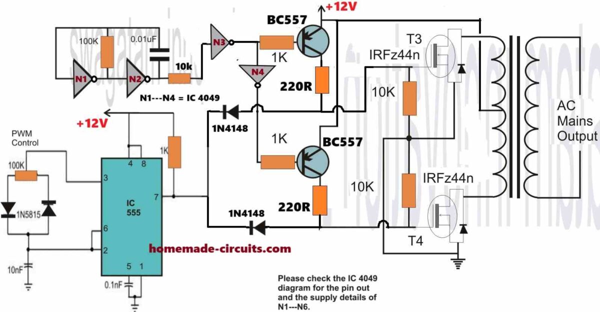
Four IC4049s have been employed in this design. A single 4049 consists of 6 NOT gates or inverters, so in all 24 of them have been used here.
Two of gates are wired up for generating the basic required square wave pulses and the rest of the gates are simply held as buffers for driving the next relevant stages.
Each transformer utilizes a couple of gates and the respective high current Darlington transistors which function as the driver transistors. The associated gates conduct alternately and drive the transistors in accordance.
The mosfets which are connected to the driver transistors respond to the above high current signals and start pumping the battery voltage directly into the winding of the respective transformers.
Due to this an induced high voltage AC starts flowing through the complementary output winding of all the involved transformers, generating the required AC 220 V or 120 V at the respective outputs.
These voltage become available in small pockets, so only the relevant magnitude of power can be expected from each of the transformers.
The 555 section takes care of the square wave output generated from the oscillator stage such that these are broken into sections and optimized for replicating a modified sine wave output.
All the MOSFET stages after the BC557 stage should be repeated for acquiring discrete power output sections, the common input of all these MOSFET stages must be joined in parallel with each other.
Each of the transformer may be rated at 200 VA, so together, 11 stages (after the BC557 stage) would provide roughly outputs up to 2000 VA.
Though using many transformers instead of a single might look like a small drawback, the actual need of deriving 2000 VA using ordinary parts and concepts finally becomes achievable from the above design very easily.


Comments
hello sir. I tried making the 555 based inverter but after the Not gate and the mosfet side, the voltage was 7v and 12v at the mosfets
Hi Hillary, There was a slight problem with the previous schematic, I have corrected it now, please check it now and modify your circuit accordingly…and let me know how it goes…
is it possible with a transformer or without a midpoint?
Yes that’s possible, using the following concept:
https://www.homemade-circuits.com/easy-h-bridge-mosfet-driver-circuit-for-inverters-and-motors/
please Sir l like to know more about this inverter l want learn it sir and l want no how to build it sir please lneed your help about it l need the original circuit diagram break down of it sir so I can build it too for my pumping machine out home sir
Adetunji, the basic working princicple of all inverter is the same. You just need an oscillator circuit to drive the mosfets and the transformer. For more info you can read the following article:
How to Design an Inverter – Theory and Tutorial
How can I determine which component to use make occilator for the inverter
the frequency output must be 50 Hz or 60 Hz, this can be calculated using formula or through practical test using a frequency meter.
Pls sir can you drop me a more elaborate circuit schematic. Just like u did with the 500watt inverter. I did construct the 500watt inverter and it’s working perfectly.
I am glad it is working, in that case you can simply upgrade the 500 watt design to 2000 watt, by using more number of MOSFETs in parallel, a 2kv transformer, and a 500 Ah battery.
Hi Swagatam sir,
I have observed in few inverters less than 1000watts, inside of it there is transformer which is different from normal transfomer or central taped. on primary side it has five leads… and inverter transformers are in small size.. is there any difference between normal transfomers and inverter transformers? And i found that core is ferrite.. is it effect on transformer size… ?For normal power supplys i found iron core… and for inverters ferrite core transformers there? is it standards…! Please help me in this.
Hi Kiran,
Ferrite transformers are compact alternative of the iron core transformers. You can read more about it here:
https://www.homemade-circuits.com/how-to-design-and-calculate-ferrite-core-transformers-for-inverters/
All transformers work with the same principle, there are no special categories for different applications…only the material, winding specs change, but working principle remains the same.
I need your help on this sir,. I built a 2000w inverter circuit with 12 irf3502 mosfets, 6 of them on either side, and transistor tip41 as the driver of the irf3502 mosfets and ic sg3524 as the driving ic. Each time I turn on the circuit, it would work for seconds with strong heating effect on the mosfets, and would destroy one of the tip41 transistors. However, I did not connect protective diode. Is there any need for protective diodes on the output of the mosfets as it could be the course of the transistor destruction?
Chinomso, first of all TIP41 is not required for driving mofests. You can do it with much smaller transistors, however in your circuit the TIP could have got burnt wrong connections of the TIP, and not because of the reverse diode on the mosfets. Having said that, reverse diode are necessary and you should connect them across the mosfets channels or across the respective trafo winding
Can a 2000watts voltage regulator (stabilizer) transformer be used as power transformer for the 2000watts inverter circuit?. If yes, please can you suggets the winding procedure, which would include: the wire guages and the number of wire turns for both the primary and secondary side. Thanks
sorry I do not know how to modify a stabilizer transformer into an inverter transformer, a professional trafo designer will know that better.
Can the output of all the transformers be connected in paralell?
No…
sir it means that 11 transformers will be required and 3 ic 4049 i think repeating your 1 kva is better whats your view
Puneet, the above circuit could be lengthy but will give no troubles while building and testing
Please send all part list
click the diagram, it's given in the diagram itself.
Please send part list
sir i have a transformer that was use for 1500w ups, the primary has 4tap and secondary has 2tap will it be aplicable for this circuit, please respond to southern.tech59@gmail.com
Abraham,
You can try this one instead, it's much simpler and reliable.:
1.bp.blogspot.com/-z9RRPSTi8zs/UbR4uKyuLRI/AAAAAAAAESo/rGu-sAhOqio/s1600/IC%204047%20inverter%20circuit.jpg
30nos 3 watt leds will not work with 6v/4.5ah batt
hello sir, kindly send me your contact, so that we can talk biz
Hello Abdul,
Making an inverter rated as high as 2000VA is not easy unless you are an expert in electronics. I have published many designs of smaller versions, you can try any one these ans upgrade it to higher levels step wise:
https://www.homemade-circuits.com/p/sine-wave-inverters.html
hello sir, am an student. my project is to build a simple inverter. 2000va,24v.
please help me sir. i need to know how to go about it sir.
i want to know d materials (components) to buy. please help me sir. thank u
hello sir, am an electrical student. my project is to build a 2000va,24v inverter.
i have searched the internet but couldnt get how to go about it. pls help me sir.
writing a good proposal is another challenge pls. i have not bought any material
Please contact me on my email ID, it's given in "contacts"
are you well versed with electronic basics? otherwise you shouldn't attempt.