In this article I will be discussing a list of simple 12V battery charger circuits which are very easy and cheap by its design yet extremely accurate with its output voltage and current specs.
All the designs presented here are current controlled meaning their outputs will never go beyond a predetermined fixed current level.
UPDATE: Looking for a high current battery charger? These powerful Lead Acid battery charger designs might help you to fulfill your requirement.
UPDATE: Looking for a car or an automobile battery charger circuit? Make sure to read this article on Regulated Car Battery Charger Circuit for Garage Mechanics
Simplest 12 V Battery Charger
As I have reiterated in many articles, the main criteria to charge a battery safely is to keep the maximum input voltage slightly below the full charge spec of the battery, and keep the current at a level that does not cause warming of the battery.
If these two conditions are maintained you can charge any battery using a minimal circuit as simple as the following one:
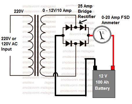
In the above simplest layout the 12 V is the RMS output of the transformer. That means, the peak voltage after rectification will be 12 x 1.41 = 16.92 V.
Although this looks higher than the 14 V full-charge level of the 12 V battery, the battery is not actually harmed due to the low current specification of the transformer.
That said, it is advisable to remove the battery as soon as the ammeter reads near zero volts.
Auto Shut-OFF: If you want to make the above design to auto shut off when the full charge level is reached, you can easily accomplish this by adding a BJT stage with the output as shown below:
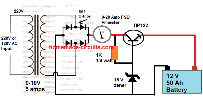
In this design, we have used a common emitter BJT stage which has its base clamped at 15 V, which means that the emitter voltage can never go beyond 14 V.
And when the battery terminals tend to reach above the 14 V level, the BJT gets reversed biased and simply goes into an auto shut down mode. You can tweak the 15V zener value until you have around 14.3 V at the output for the battery.
This transforms the first design into a fully automatic 12 V charger system, which is simple to build yet entirely safe.
Also, since there's no filter capacitor the 16 V is not applied as a continuous DC, rather as 100 Hz ON/OFF switching. This causes less stress on the battery, and also prevents sulfation of the battery plates.
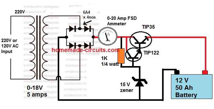
For High Current Battery Charging, the above Schematic can be Modified as Shown Below:
Why Current Control is Important (Constant Current Setup)
Charging any form of chargeable battery can be critical and involves some attention to be paid. When the input current at which the battery is being charged is significantly high, adding a current control becomes an important factor.
We all know how smart the IC LM317 is and it’s no surprise why this device finds so many applications requiring precise power control.
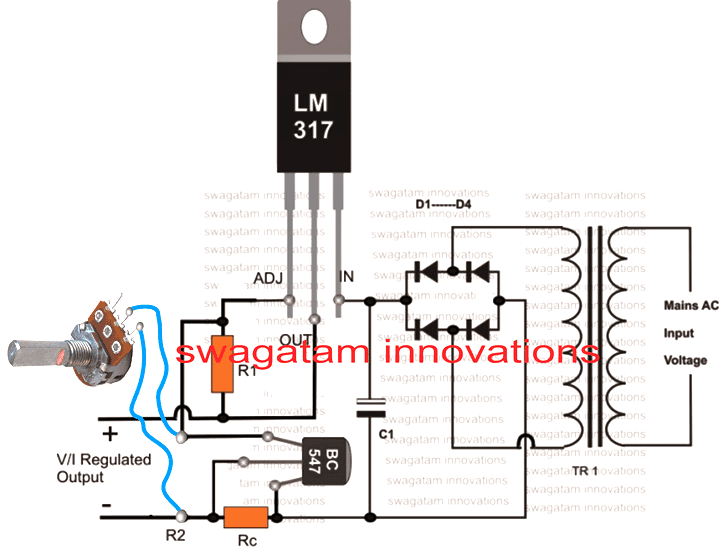
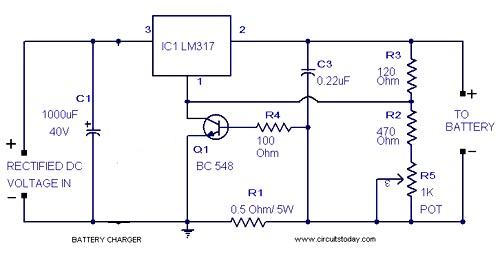
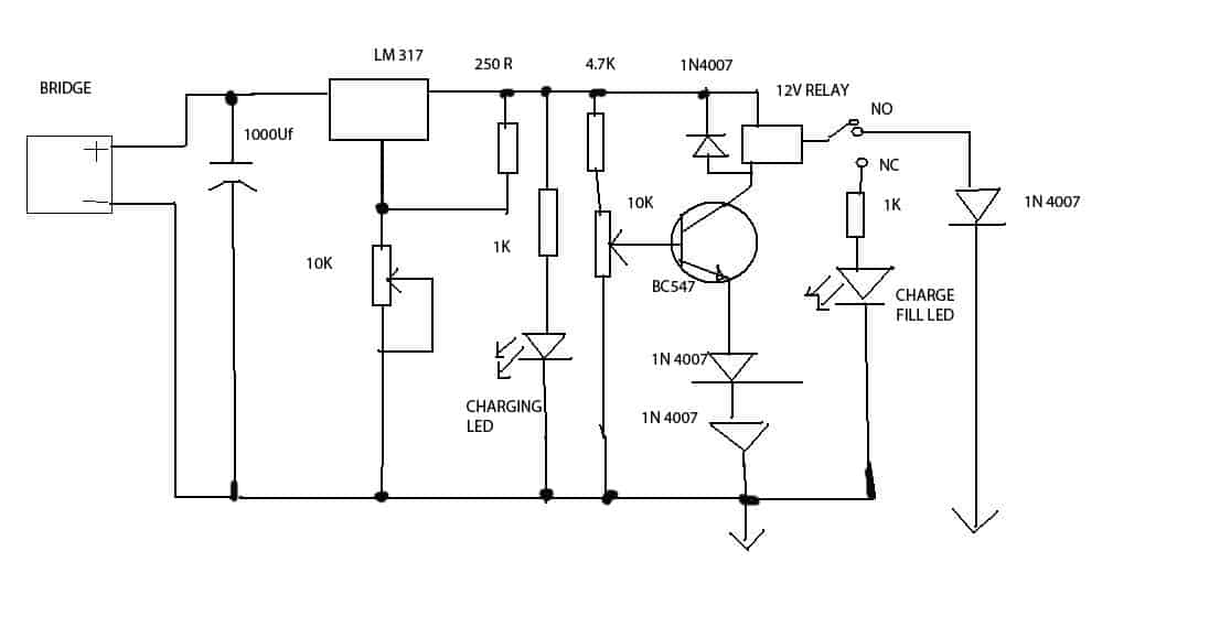
The Current Controlled 12V Battery Charger Circuit Using IC LM317 presented here shows how the IC LM317 can be configured using just a couple resistors and an ordinary transformer bridge power supply for charging a 12 volt battery with utmost accuracy.
How it Works
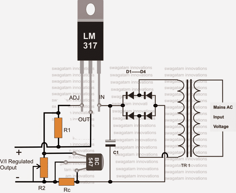
The IC is basically wired in its usual mode where R1 and R2 are included for the required voltage adjustment purpose.
The input power to the IC is fed from an ordinary transformer/diode bridge network; the voltage is around 14 volts after the filtration via C1.
The filtered 14 V DC is applied to the input pin of the IC.
The ADJ pin of the IC is fixed to the junction of the resistor R1 and the variable resistor R2. R2 can be fine set for aligning the final output voltage with the battery.
Without the inclusion of Rc, the circuit would behave like a simple LM 317 power supply where the current wouldn't be sensed and controlled.
However with Rc along with BC547 transistor placed in the circuit at the shown position makes it capable of sensing the current that’s being delivered to the battery.
As long as this current is within the desired safe range, the voltage remains at the specified level, however if the current tends to rise, the voltage is withdrawn by the IC and dropped, restricting the current rise any further and ensuring appropriate safety for the battery.
The formula for calculating Rc is:
R = 0.6/I, where I is the maximum desired output current limit.
The IC will require a heatsink for operating optimally.
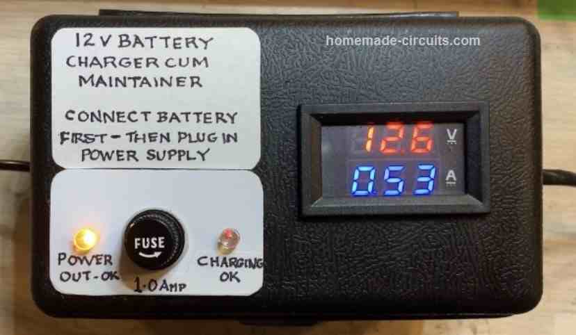
The connected ammeter is used for monitoring the charge condition of the battery. Once the ammeter shows zero voltage, the battery may be detached from the charger for the intended use.
Circuit Diagram #1
Parts List
The following parts will be required for making the above explained circuit
- R1 = 240 Ohms,
- R2 = 10k preset.
- C1 = 1000uF/25V,
- Diodes = 1N4007,
- TR1 = 0-14V, 1Amp
How to Connect pot with LM317 or LM338 Circuit
The following image shows how the 3 pins of a pot needs to be correctly configured or wired with any LM317 voltage regulator circuit or a LM338 voltage regulator circuit:
As can be seen the center pin and any one of the outer pins is selected for connecting the potentiometer or the pot with the circuit, the third unconnected pin is kept unused.
Circuit Diagram #2
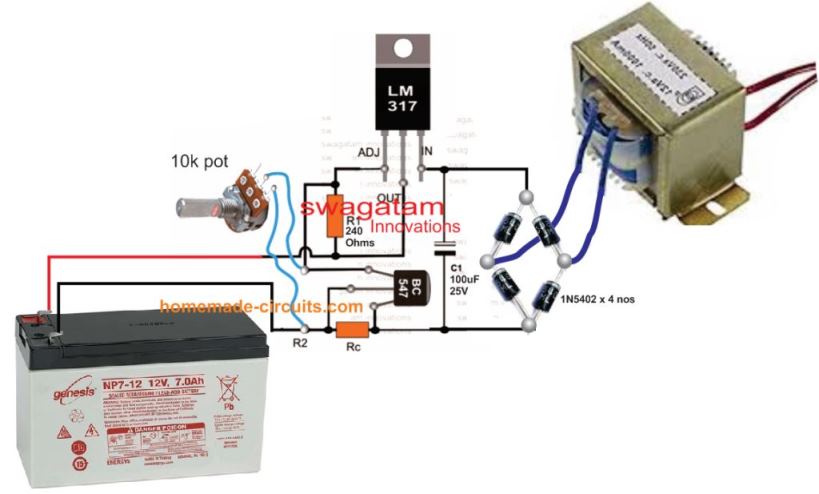
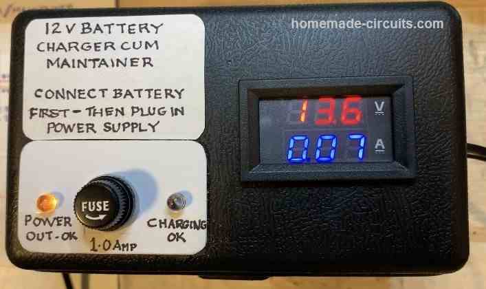
Practical Results
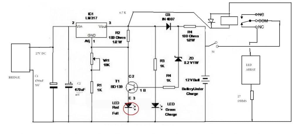
The above LM317 battery charger circuit was suitably modified using fixed resistors, by one of the dedicated members of this blog Mr. V. The modified circuit was then utilized to charge a battery optimally and safely.
The following circuit diagrams exhibit how this was implemented, and the next prototype image shows the test results.
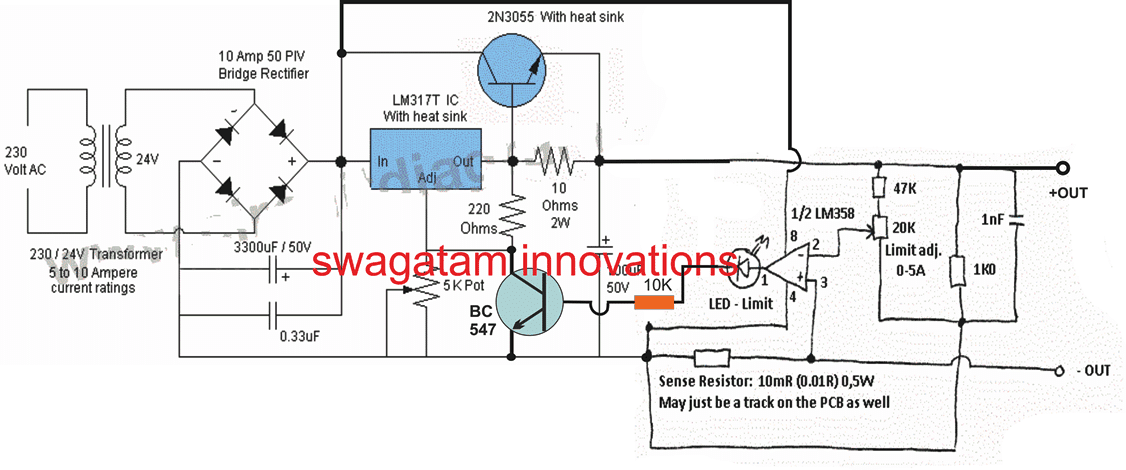
Adjustable High Current LM317 Battery Charger Circuit #3
For upgrading the above circuit into a variable high current LM317 battery charger circuit, the following modifications can be implemented:
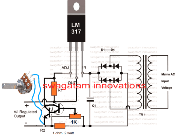
Adjustable Current Charger Circuit #4
5) Compact 12 volt Battery Charger Circuit Using IC LM 338
The IC LM338 is an outstanding device which can be used for unlimited number of potential electronic circuit applications. Here we use it to make an automatic 12V battery charger circuit.
Why LM338 IC
Basically the main function of this IC is voltage control and can also be wired for controlling currents through some simple modifications.
Battery charger circuit applications are ideally suited with this IC and we are going to study one example circuits for making a 12 volt automatic battery charger circuit using the IC LM338.
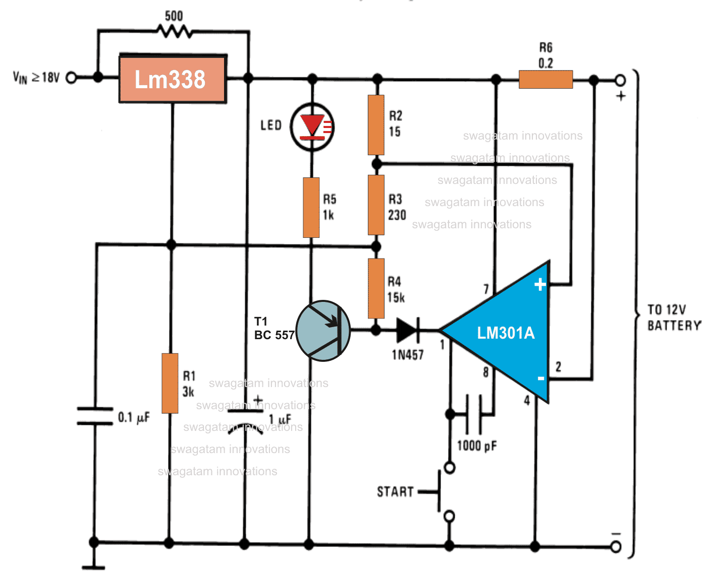
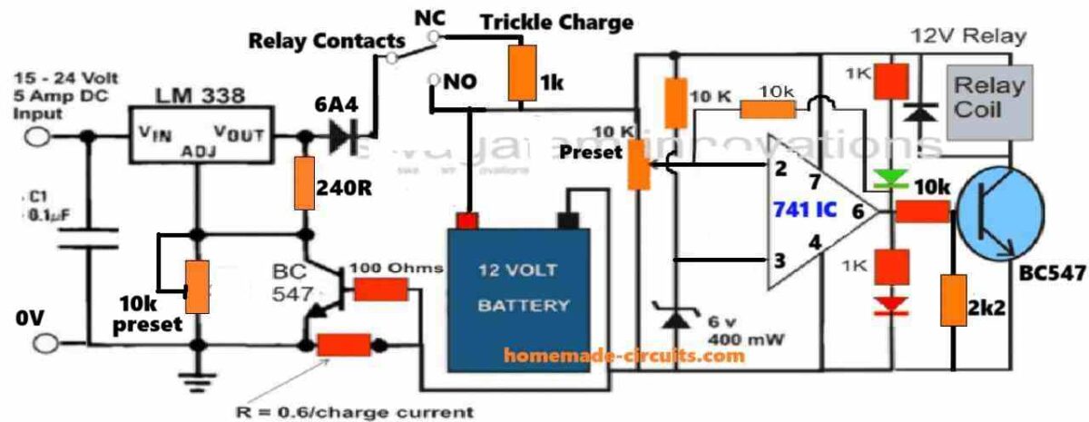
Referring to the circuit diagram we see that the entire circuit is wired around the IC LM301, which forms the control circuit for executing the trip off actions.
The IC LM338 is configured as the current controller and as the circuit breaker module.
Using LM338 as a Regulator and Opamp as the Comparator
The whole operation can be analyzed trough the following points:The IC LM 301 is wired as a comparator with its non inverting input clamped to a fixed reference point derived from a potential divider network made from R2 and R3.
The potential acquired from the junction of R3 and R4 is used for setting the output voltage of the IC LM338 to a level that’s a shade higher than the required charging voltage, to about 14 volts.
This voltage is fed to the battery under charger via the resistor R6 which is included here in the form of a current sensor.
The 500 Ohm resistor connected across the input and the output pins of the IC LM338 makes sure that even after the circuit is automatically switched OFF, the battery is trickle charged as long as it remains connected to the circuit output.
The start button is used to initiate the charging process after a partially discharged battery is connected to the output of the circuit.
R6 may be selected appropriately for acquiring different charging rates depending upon the battery AH.
Circuit Functioning Details (As Explained By +ElectronLover)
" As soon as the connected battery is charged fully, the potential at the inverting input of the opamp becomes higher than the set voltage at non-inverting input of the IC. This instantly switches the output of the opamp to logic low."
According to my assumption:
- V+ = VCC - 74mV
- V- = VCC - Icharging x R6
- VCC= Voltage on pin 7 of Opamp.
When The battery charges fully Icharging reduces. V- become greater than V+, output of the Opamp goes low, Turning on the PNP and LED.
Also, R4 gets a ground connection through the diode. R4 becomes parallel to R1 reducing the effective resistance seen from the pin ADJ of LM338 to GND.
Vout(LM338) = 1.2+1.2 x Reff/(R2+R3), Reff is the Resistance of pin ADJ to GND.
When the Reff reduces the output of LM338 reduces and inhibit charging.
Circuit Diagram
6) 12V Charger Using IC L200
Are you looking for a constant current charger circuit to facilitate a safe charging battery? The 5th simple circuit presented here using the IC L200 will simply show you how to build a constant current battery charger unit.
Importance of Constant Current
A constant current charger is highly recommended as far as maintaining safety and long battery life is concerned. Using the IC L200, a simple yet a very useful and powerful automobile battery charger providing constant current output can be built.
I have already discussed many useful battery charger circuits through my previous articles, some being too accurate and some much simpler in design.
Although the main criteria involved with charging batteries largely depends on the type of the battery, but basically it’s the voltage and the current which particularly needs appropriate dimensioning to ensure an effective and safe charging of any battery.
In this article I have explained a battery charger circuit suitable for charging automobile batteries equipped with visual reverse polarity and full-charge indicators.
The circuit incorporates the versatile but not so popular voltage regulator IC L200 along with a few external complementing passive components to form a full fledged battery charger circuit.
Let’s learn more about this constant current charger circuit.
Circuit diagram using L200 IC
Circuit Operation
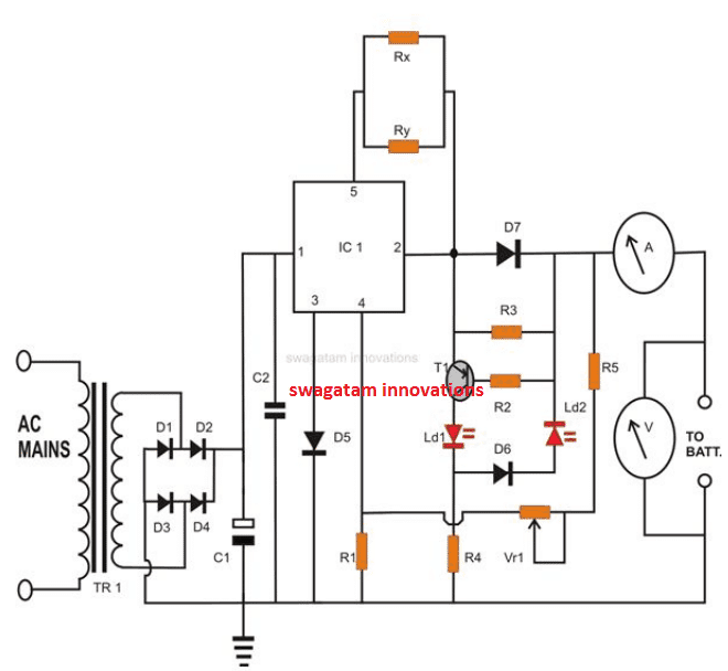
The IC L200 produces a good voltage regulation and therefore ensures a safe and a constant current charging, a must for any kind of chargeable battery.
Referring to the figure, the input supply is acquired from a standard transformer/bridge configuration, C1 forms the main filter capacitor and C2 being responsible for grounding any left residual AC.
The charging voltage is set by adjusting the variable resistor VR1, with no load connected at the output.
The circuit includes a reverse polarity indicator using LED LD1.
Once the connected battery becomes fully charged i.e. when its voltage becomes to the set voltage, the IC restricts the charging current and stops the battery from over charging.
The above situation also reduces the positive biasing of T1 and creates a potential difference of above -0.6 volts, so that it starts conducting and switches LD2 ON, indicating that the battery has reached its full charge and may be removed from the charger.
The resistors Rx and Ry are the current limiting resistors required to fix or determine the maximum charging current or the rate at which the battery needs to be charged. It is calculated using the formula:
I = 0.45 (Rx + Ry) / Rx.Ry.
The IC L200 may be mounted on a suitable heatsink to facilitate consistent charging of the battery; however the built-in protection circuitry of the IC virtually never allows the IC to get damaged. It typically includes built-in thermal run away, output short circuit and over load protections.
Diode D5 ensures that the IC doesn’t get damaged in case the battery accidentally gets wrongly connected with reverse polarities at the output.
Diode D7 is included to restrict the connected battery from getting discharged through the IC in case the system is switched OFF without disconnecting the battery.
You may quite easily modify this constant current charger circuit to make it compatible with the charging of a 6 Volt battery by doing the simple changes in the value of a few resistors. Please refer the parts list to get the required info.
Parts list
- R1 = 1K
- R2 =100E,
- R3 = 47E,
- R4 = 1K
- R5 = 2K2,
- VR1 = 1K,
- D1—D4 AND D7 = 1N5408,
- D5, D6 = 1N4148,
- LEDS = RED 5mm,
- C1 = 2200uF/ 25V,
- C2 = 1uF/25V,
- T1 = 8550,
- IC1 = L200 (TO-3 Package)
- A = Ammeter, 0-5amp,
- FSDV =Voltmeter, 0-12Volt FSD
- TR1 = 0 - 24V, current = 1/10 of the battery AH
How to Set up the CC Charger Circuit
The circuit is set up in the following manner:
Connect a variable power supply to the circuit.
Set the voltage close to the upper threshold volt level.
Adjust the preset so that the relay remains activated at this voltage.
Now raise the voltage slightly more to upper threshold volt level and again adjust the preset such that the relay just trips off.
The circuit is set, and can be used normally using a fixed 48 volts input for charging the desired battery.
A request from one of my followers:
Hi Swagatam,
I got your email from a website www.brighthub.com where you shared your expertise with regards to construction of a battery charger.
Please i have a little problem that i hope you could help me out:
I am just a layman with no much knowledge of electronics.
I have been using a 3000w inverter and recently i discovered it doesnt charge the battery (but inverts). We have no much experts around here and for fear of further damaging it, i decided to get a separate charger to charge the battery.
My question is: the charger i got has an output of 12volts 6Amps will that charge my dry-cell battery with 200ahs capacity?
If yes, how long will it take to full and if no, what charger capacity do i get to serve that purpose? I have had experience in the past where a charger damaged my battery and i don't want to risk that this time.
Many thanks.
Habu Maks
My Answer to Mr. Habu
Hi Habu,
The charging current of a charger should be ideally rated at 1/10 of the battery AH. That means for your 200 Ah battery the charger must be rated at around 20 Amps.
At this rate the battery will take around 10 to 12 hours for getting fully charged.
With a 6 amp charger it may take ages for your battery to get charged, or simply the charging process might fail to initiate.
Thanks and Regards.
7) Simple 12V Battery Charger Circuit with 4 LED Indicator
A current controlled automatic 12V battery charger circuit with 4 LED indicators can be learned in the following post. The design also includes a 4 level charging status indicator using LEDs. The circuit was requested by Mr. Dendy.
Battery Charger with 4 LED Status Indicator
I would like to ask and look forward to you to be made Automatic cellphone charger circuit 5 Volt and Battery Charger Circuit 12 V (in the schematic circuit and the first transformer CT) automatic / cut off by using a battery indicator and
LED lights red as an indicator were charging (Charging On Indicator) using IC LM 324, and
LM 317 and a full battery using a green LED and breaking electrical current when the battery is full.
For cellphone charger circuit 5 Volt I want to have levels of the following indicators:
0-25% battery is in the charger using a red LED.25-50% using a blue LED (red LED goes out)55-75% using a yellow LED (LED red, blue outages)75-100% using a green LED (LED red, blue, yellow outages) next to Battery Charger Circuit 12 V I want to use the 5 LED lights as follows:0-25% using a red LED25-50% using orange LED (red LED goes out)50-75% using a yellow LED (LED red, orange outages)75-100% using a blue LED (Led red, orange, yellow outages)more than 100% using the green LED (LED red, orange, yellow, blue outages).
I hope you, the components are common and accessible and made a circuit schematic above as soon as possible because I really need schematics details.
I hope you will help me to find a better solution.
The Design
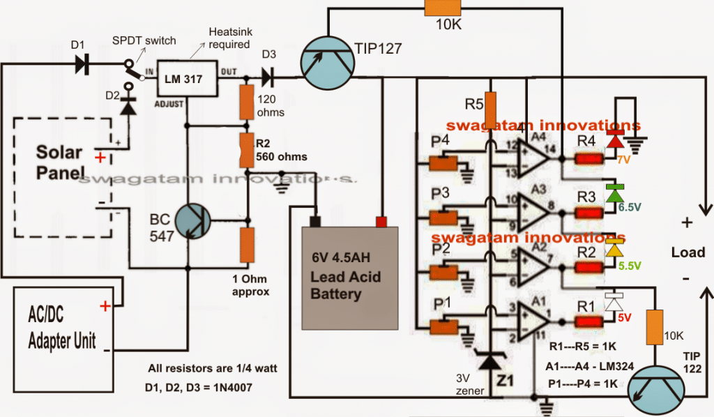
The requested design make use of 4 level status indicator and can be witnessed below.
The TIP122 controls over-discharge of the battery while the TIP127 ensures an instant supply cut-of for the battery, whenever an overcharge limit is reached for the battery.
The SPDT switch can be used to select the battery charging either from a mains adapter or from a renewable energy source such as a solar panel.
Circuit Diagram
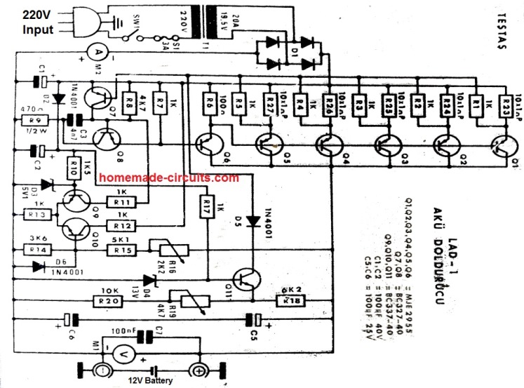
UPDATE:
The following tested 12V charger circuit schematic was sent to be by "Ali Solar" with a request to share it in this post:
Smart 12V Battery Charger Circuits
The following automatic 12V smart battery charger circuit was exclusively designed by me in response to requests from two keen readers of this blog, Mr. Vinod and Mr.Sandy.
Let's hear what Mr.Vinod discussed with me through emails regarding the making of a smart battery charger circuit:
8) Discussing a Personal 12V Battery Charger The Design
"Hi Swagatam, My name is vinod chandran. Professionally i am a dubbing artist in malayalam film industry but i am an electronic enthusiast too. I am a regular visitor of your blog. Now i need your help.
I just built an automatic SLA battery charger but there is some problems with that. I am attaching the circuit with this mail.
The red LED in circuit is supposed to glow when battery is full but it glows all the time .(my battery shows only 12.6v).
Another problem is with 10k pot. there is no difference when i turn the pot left and right. . So i request you to either correct these problems or help me to find an automatic charger circuit which gives me a visual or audio alert when battery is full and low .
As a hobbyist i used to make things from old electronic appliances. For the battery charger i have some components. 1. Transformer from an old vcd player. out put of 22v, 12v,3.3v.
And i don't know how to measure ampere. My DMM has only the ability to check 200mA. It has a 10A port but i can't measure any ampere with that.(meter shows "1") So i assumed that the transformer is above 1A and below 2A with the size and requirements of the vcd player. 2. Another transformer -12-0-12 5A 3.
Another transformer - 12v 1A 4. Transformer from my old ups(Numeric 600exv). Is this transformer's input is regulated AC ? 5. couple of LM 317's 6. SLA battery from old ups- 12v 7Ah. (Now it has a 12.8v charge) 7.
SLA battery from old 40w inverter - 12v 7Ah. ( the charge is 3.1v) One thing i forgot to tell you.
After the first charger circuit, i made another one (i'll attach this too). This is not an automatic one but it is working. And i need to measure the ampere of this charger.
For that purpose i googled for an animated circuit simulation software but didn't get one yet.
But i can't draw my circuit in that tool. there is no parts like LM317 and LM431(variable shunt regulator). not even a potentiometer or led.
So i request you to help me to find a visual circuit simulation tool. I hope you will help me. regards
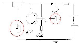
Hi Vinod, The red LED should not glow all the time and turning the pot should change > the output voltage, without the battery connected.
You can do the following things: > > Remove the 1K resistor in series with the 10K pot and connect the pot's relevant terminal directly to ground.
Connect a 1K pot across the base of the transistor and ground (use center and any one of the other terminals of the pot).
Remove everything that's presented at the right side of the battery in the diagram, I mean the relay and all.....
Hopefully with the above changes, you should be able to adjust the voltage and also adjust the base transistor pot for making the LED glow only after the battery is fully charged, at around 14V.
I don't trust and use simulators, I believe in practical tests, which is the best method of verifying. For 12v 7.5 ah battery, use a 0-24V 2amp transformer, adjust the output voltage of the above circuit to 14.2 vollts.
Adjust the base transistor pot such that the LED just starts to glow at 14V. Do these adjustents without the battery connected at the output.
The second circuit is also good but is not automatic....is current controlled, though. Let me know your thoughts. Thanks, Swagatam
Hi Swagatam,
First of all let me say thank you for your fast replying. I will try your suggestions. before that i need to confirm the changes you mentioned. I will attach an image consisting your suggestions. So please confirm the changes in the circuit.
Hi Vinod,
That's perfect.
Adjust the transistor base preset until the LED just starts glowing dimly at around 14 volts, with no battery connected.
Regards.
Hi Swagatam Your Idea is great. The charger is working and now one LED is glowing to indicate the charging is in progress. but how can i configure the charge full indicator LED. When i turn the pot to ground side (means lower resistance) LED starts glowing.
when resistance goes high LED will be off. After 4 hours of charging my battery shows 13.00v. But that charge full LED is off now. Plz help me.
I am sorry disturb you again. The last email was a mistake. i didn't see your suggestion correctly. So please ignore that mail.
Now i adust the 10k pot to 14.3v(it's quite difficult to adjust the pot, because a slight variation will result a bigger voltage output. ). And i adjust the 1k pot to glow a little. Is this charger supposed to indicate a 14v battery?. After all let me know the danger level full charge of the battery.
As you suggested, everything was alright when i test the circuit from breadboard. But after solder into PCB thing are happening strangely.
The red LED is not working. charging voltage is ok. Anyway i am attaching the image that shows the present condition of the circuit. plz help me. After all let me ask you one thing. Could you please give me an automatic charger circuit with a battery full indicator. ?.
Hi swagatam, Actually i am in the middle of your automatic charger with hysteresis feature. I just added a few modifications . i will attach the circuit with this mail. plz check this out. If this circuit is not ok then i can wait for you to tomorrow .
Simple Circuit Diagram #8
I forgot to ask one thing. My transformer is about 1 - 2 A. I don't know what is the correct. how can i test with my multimeter?.
Besides if it is a 1A or 2A transformer, how can i reduce the current
to 700mA.
regards
Hi Vinod, The circuit is OK, but won't be accurate, will give you a lot of trouble > while adjusting.
A 1 amp transformer would provide 1amp when short circuited (check by connecting the meter prods to the supply wires at 10amp range and set to either DC or AC depending upon the output).
Meaning the maximum power of is 1 amp at zero volts. You may use it freely with a 7.5 Ah battery, it won't do any harm, as the voltage would drop to the battery voltage level at 700 ma current and the battery would get safely charged. But remember to disconnect the battery when the voltage reaches 14 volts.
Anyway, a current control facility would be added in the circuit that I would be providing you, so there's nothing to worry
Regards.
I'll provide you with a perfect and easy automatic circuit, please wait until tomorrow.
Hi swagatam,
I hope you will help me to find a better solution. Thank you.
regards
vinod chandran
In the meantime, another keen follower of this blog Mr.Sandy also requested a similar 12V smart battery charger circuit through comments.
So finally I designed the circuit which will hopefully satisfy the needs of Mr.Vinod and Mr.Sandy for the intended purpose.
The following 9th figure shows an automatic 3 to 18 volts, voltage controlled, current controlled, double stage battery charger circuit with standby charging feature.
Circuit Diagram #9
How to Set up the Circuit
The circuit can be set up using the following points:
1) Initially, keep the power switched OFF, and keep the 10k feedback resistor between pin#6 and pin#2 disconnected.
2) Do not connect any battery yet.
3) Adjust the 10k preset wiper fully towards the ground supply side.
4) Adjust the LM338 output voltage to the full-charge battery level.
5) Short circuit the LM338 output with the N/O of the relay, so that the LM338 output voltage gets connected directly with the opamp circuit.
6) Switch ON the power supply to the LM338 input.
7) The red LED should light up, and the relay should click ON.
8) Now slowly adjust the 10k preset until the relay just clicks OFF.
9) This will also turn OFF the green LED and turn ON the red LED.
10) That's all, the circuit is fully set now, remove the shorting between the LM338 output and the N/O contact, and reconnect the 10k feedback resistor.
11) You can test the actual auto cut-off function of the circuit by connecting a discharged battery across the indicated battery points.
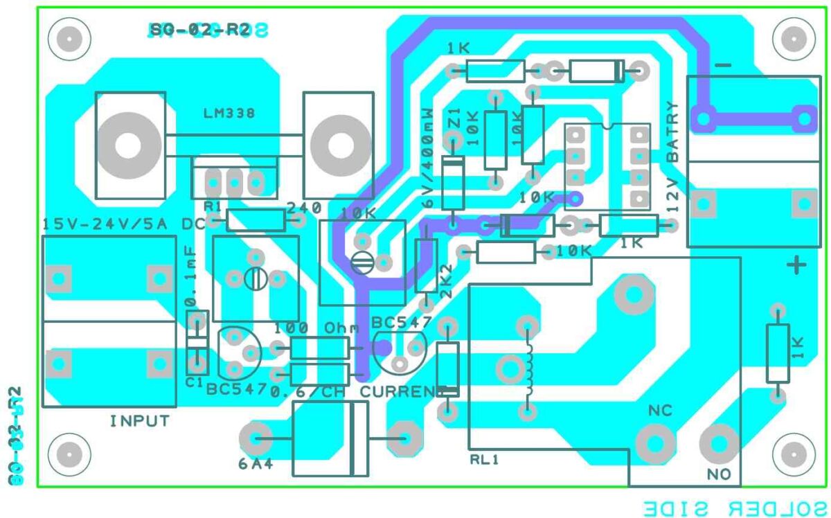
PCB Designs and Gerber Files
The following PCB design and the Gerber file details were kindly contributed by Mr. Sudipta Ghose who is an avid reader of this blog. I am grateful to him for his kind contributions to this website.


Comments
Hi Swagatham
You say the over current formula is 0.6v/ ohm which is 0.6amps, which or what is the resistance referred to for calculating this over current
Is there a way to protect the LM317 circuit, at present I have a 2.0 A fuse at the output of the device to protect the SMPS power supply should I put a smaller fuse instead
Thanks Swagatham
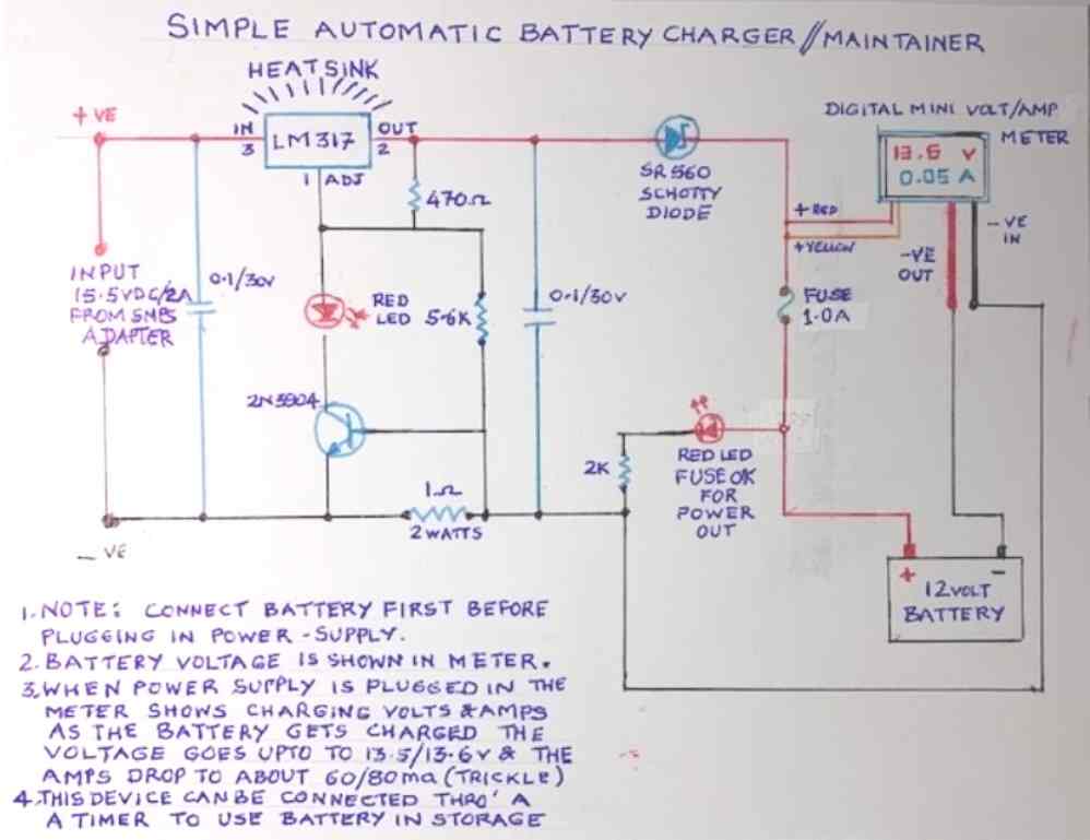
Hi Swagatham
Tried in trial & error and found that a 5.6 k resistor between the 470 ohm at pin one of IC and base of transistor gives an output of 14 vdc which I think is good
When connected to the battery which is fairly charged and is at 12.6 volts it starts charging at about 450ma and then goes down to about 210 ma and now is at 190 ma and 13.4 volts and remains like this for more than 20 minutes
Is this ok and safe, the lm317 is slightly warm
Can I keep it like this ?
Another ? is why is the red led not glowing is it supposed to be like that like a diode only
Thanks Immensely & God bless
Hi Val,
It looks OK and safe to me. You can keep it like this.
The safe and the recommended charging current for a lead acid battery is 1/10th of its Ah value.
The RED LED will illuminate only when there is an over current.
Over current formula is = 0.6 V / 1 ohm = 0.6 amps
All the best to you!
I am novice in electronic communication help me by suggestions ok
Good day Sir, Swag, please I made small 12v different chargers with 330mA, 500mA and 770mA with individual charging current.
But when I parallelled the Ac supply the rectified, total charging current was 675mA.
What could be the cause? Is it advisable to charge individually?
Hello Tinu,
which circuit did you use for making the chargers?
I did basic smps
OK, then you used a common bridge rectifier for supplying all the chargers, right? Did you measure the current with load connected to all the chargers individually? And where did you measure the current, is it in series with the common bridge rectifier positive?
Hello Swagatam, I have 3 batteries, all 12 volts but two are 150Ah and one is 200Ah connected in parallel, Sir, I need a simple charger circuit to charge them. Good God Bless your wisdom.
Thank you Itari,
You can try the following simple power supply circuit for charging your batteries. Make sure to calculate the RX value appropriately using the formula provided in the diagram. For the output voltage, you simply have to adjust the output 14 V using the 10K pot.
https://www.homemade-circuits.com/wp-content/uploads/2022/11/high-power-battery-charger-circuit-using-TIP35.jpg
Hello Swagatam, if I have 100ah 12v batteries two pieces and a 24v inverter. What should be the specifications of my charger for the two batteries connected in series? 20amp or 10amps.
Hello Morris,
When the batteries are connected in series the charging current will remain the same but voltage will become double. So for the charging current you will have to use 10% of the Ah rating which 10 amps, and for the voltage it should be 28 V (full charge voltage)
Hi Swagatam;
Car toy has 2 x 6 V 12 A batteries connected in serial (namely car runs with 12 V). Although the batteries are 12 A capacity there is a 16 A fuse in the circuit. Please share your comments for the followings;
1- If batteries are 12 A then why fuse is 16 A. That is normal?
2- What would be the charging voltage and current if the batteries are connected as serial like that.
Best Regards
Hi Suat,
16 amp fuse is actually wrong. The fuse must be rated as per the load’s maximum current rating.
The charging voltage for a 12V battery should be 14 V, and the charging current should be below 2 amps if the batteries are lead acid batteries.
Hi Swagatam;
I have the transformer 220 V AC to 24 V AC and 100 VA. Please advice if possible to charge the battery
12 V 100 A by using that transformer.
Best Regards
Hi Suat,
You will need a buck converter circuit such as the following one. You can adjust R8, R9 values to get 14V at the output from 24V input DC or higher.
https://www.homemade-circuits.com/5v-pwm-solar-battery-charger-circuit/
when I check the parts, it may be subject that I cannot find the transistors as NTE153,331 and 6013 here in my area. However I will search them. Meanwhile I have realized the above “circuit #3 adjustbale high current LM317 Battery Charger” also the transformer was same as my transformer.(output 24 Volts) Please advice if it is also equivalent. Best regards
Those transistors and diode can be replaced with any equivalent types, no issues.
The circuit#3 is again a linear circuit, meaning the transistor and the IC can get very hot.
However since the transistor is handling the bulk of the output current, the IC may remain relatively cooler.
You can try that circuit, hopefully it might solve the problem.
Hi Swagatam;
Car toy has 2 batteries (2 x 6 V 12 A) but one of the batteries is dead. So I will intend to use 12 V 7 A battery instead of dead one with the 7806 voltage regulator.
My questions:
1- As seen above currents are different does that cause any problem?
2- Please advise if any circuit is avalable instead of 7806? Best Regards
Hi Suat,
If you use a 7806 IC it will become very hot and waste a lot of energy. And when it becomes hot it will not allow the toy car to operate correctly. Also, the 7806 will not allow more than 1 amp current to the load. You can try building a 12V to 6V buck converter which will be more efficient. However, I don’t have this circuit with me at this moment, I will try to find it and post it soon if possible.
Hello Swagatam, thank you for the very rich content that you offer us through your blog.
I would like to design a charger to charge a 12V/7AH battery exactly as in the circuit diagram2, as you have explained the output voltage will be 14.4v with a current of 0.7A.
However I would like to know how to make the charge disconnect automatically when the battery is full or limit the current.
Thank you in advance for your answer.
Thank you Arrow,
In circuit diagram #2 the TIP122 will switch OFF and cut off the charging current to the battery when the battery terminal reaches the full charge level, as determined by the zener diode.
If you want a more accurate cut off design then you can try the 3rd circuit under the title “[New Update] Current Dependent Battery Auto Cut OFF” from the following article:
https://www.homemade-circuits.com/high-current-10-to-20-amp-automatic/
Hi Swagatam
ok thank you for your quick answer
I see well, in fact I was talking about the fourth picture, where we used the LM317 and the BC547
Is it with this circuit there is the automatic cut off when the battery is charged
I would like to use this circuit and I would like to know how to add the option for the automatic cut off
Hi Swagatam;
I have got cordless screwdriwer set 4.8V. Charger is 6 V 0.300 mA. At the beginning battery level was fully empty and the charger was overheat. My questions;
1- At the beginning overheating is normal?
2- Which one is better? a) To keep the equipment always in charging position. or b) To keep the equipment in charging position if it needs to be recharged. Thanks and regards
Hi Suat,
Charger heating up slightly at the beginning is normal but overheating is not normal. It means your charger is not compatible with the battery which is being charged.
Both the options are correct and can be used, but make sure the equipment is never highly discharged. It is better to charge as soon as it is slightly discharged. For 4.8V battery, make sure it is charged when the voltage drops to 4.2V.
Excuse me Swagatam, but it is original battery charger adapter of the company. However it looks like an ordinary power adapter 220 to 6V. It is possible to understand if it has auto-cut-off when fully charged. Or I should find seller’s operating instruction book? Thanks and regards
Yes, I understand Suat, but overheating is a not a good sign in any situation. Or maybe this is happening due to an over discharged condition of the battery, which must be avoided at any cost.
You can add a small flashlight bulb in series with the positive line, if this bulb at some point suddenly shuts off when the battery is fully charged will indicate that the charger has an auto cut off system.
That is brand new never used so far but battery is not charged for a long period. However tool runs strongly when recharged. I have seen about 2.47 or 3 V flash light bulb those are proper for the purpose? Many Thanks
OK then the issue could be due to slightly over discharged battery drawing high amount of current. Yes 3 V can be used but the current capacity must be slightly higher otherwise the battery can take a lot of time to charge through the bulb.
Please Swagatam, can you explain the point that bulb serial connection with the positive line. What I understood is bulb will be between the positive pole of the DC adapter and the positive pole of the 4.8 Battery. So my question is in case there is no negative contact with the bulb how the bulb would light? Thanks and regards
Hi Suat, that is right, the bulb must be in series with the positive line, between the adapter positive and the battery positive. The current from the adapter will enter the bulb, reach the battery positive, enter the battery and reach the negative line through the battery negative terminal, in this way the bulb will get the current to illuminate.
Hi Swagatam;
I will use a digital volt and amp meter equipment in my adjustable voltage circuit whose input voltage is about DC 0-30 V. My transformer output is about AC 24 V but after bridge diodes and capacitor that increased value is about DC 34 V. However I intend to use less voltage to the digital meter. Please advise which one is better to use 78xx or a proper resistance before digital meter to protect it.- Regards
Hi Suat, If you limit the voltage to the meter then the output voltage of the power supply will also get limited. Why would you want to limit the voltage to the meter, since all meters have extensive ranges upto 1000V or more, so it can be easily used with 30V or more without issues.
Hi Swagatam;
I think I did mislead you. As far as I know the digital meter ranges upto 100 V and but needs input voltages to display the values between DC 0-30 V (thinner black and red cables) whereas the third yellow cable is connected to the load at the output to measure the output voltage. That means if you limited display voltage let’s say 6 V then even possible to measure voltage upto 100 V or less by connecting the yellow cable at output.Thanks and regards
Hi Suat, I have understood now. You are using a 3 wire digital meter module which requires a low DC input supply below 30 V to operate. Yes, you can use a 1K resistor with a 12V zener diode. I think this should be quite sufficient. If you want to use a 78XX then try a 7824 IC.
Good day Swagatam,
As usual, you have published an excellent collection of circuits which many people will find informative and useful. I am looking for a slightly different circuit to the ones that you have here and I am wondering if you can help me. I would like to charge a 5 AH 12 volt lead acid battery at 500ma and I would like a circuit that would use a 12 volt 1 amp wall wart as it’s power supply. I would also like an LED to show that it is charging and one that shows fully charged. Is this possible or would I need a higher voltage power supply> I have a few 1 amp 12 volt wall warts in my collection and I would like to make emergency lighting for when we have power failures. I have sourced LED strip lights and they are very bright and I run them on a 7.5 AH SLA battery and I charge them with a charger made from one of your earlier circuits and I am very happy with the performance, but these one that I would now like to make are so that I can give them away to my friends to help them out. I would be very grateful for any help that you can give me with this project.
King regards
Patrick
Thank you Patrick, Glad you found the above article useful, and the circuits worked for you!
To charge a 12V lead acid battery you will need at least a 14V DC input to the battery, 12V will not work.
I can provide you a simple circuit design which you can use to charge your 12V 5 Ah battery. Here’s the design which you can use:
Hi Swagatam,
Could you please provide a circuit that would charge a 12V Lead Acid Cell quickly , (using Cycle specs of 14.2 Volts to 14.5Volts), at an adjustable current, and once it has reached it’s goal voltage, and then for it to switch to Standby Specifications of 13.5 to 13.8Volts.
The reason for this requirement is that we have irregular Power Load Shedding, and we sometimes need to charge batteries quickly, (never knowing when the next power outage will be), yet other times can go for days, (weeks even), without any load shedding, and the higher Cycles specification, damages batteries, when their requirement is now moved to Standby use.
The load shedding typically lasts for between 3 and 4 hours, and the on time periods between shedding can be anything from 6 to 12 hours, or sometimes days, (if we’re lucky), and we typically draw down a battery to some 45 to 60% capacity during a power outage.
Hi Anthony, Can you please tell me how much is the Ah rating of the battery? I will design it soon for you once I know the Ah rating of the battery.
Hi Swagatam,
Thanks so much for your reply.
I have a couple of battery backup devices of varying capacities, however all using SLA batteries, hence me asking for adjustable charge current.
My Wireless and Fibre Router use a 12V 9AH (CSB HR1234WF2), and the Wireless and Fiber routers draw 1.2Amps max.
My lighting uses a 12V 100AH (ROYAL DEEP CYCLE – DC31), and my lighting draws 14 Amps max.
My Fridge uses two 12V 100AH (ROYAL DEEP CYCLE – DC31), in parallel, running an inverter, and draws 22Amps max.
Thanking you in advance for your assistance.
Kind regards,
Anthony
You are welcome Anthony,
You can try the following simple automatic fast charger circuit design. The 13V and 14.1 V power supplies must be adjustable current type power supplies so that you can adjust the current according to the battery specifications. For example for a 100 Ah battery you can set the 13V supply current to 30 amps, and set the 14.1V supply current to 10 amps.
I hope you know how to set the preset for the automatic changeover.
Thanks so much Swagatam,
I hadn’t thought of using a comparator … I’m going to adapt your diagram and include a Mosfet as apposed the Relay and BC547 to switch between two constant voltage sources, both to include current limiting.
I’ll send through the final working schematic if you let me know where to send it to 😉
Thanks again … Much appreciated.
No problem Anthony, you can modify the diagram as per your needs and specs. For sending the diagram you can upload it to any free image hosting site and send me the link here through comments. I will check it out. Make sure to remove the https while sending the link.
Muy buena información, felicidades Swagatam.
Saludos cordiales a todos.
Thank you Victor!
Sir. I am looking for a lithium battery charging circuit to build.30amp @14.6v Can you advise me if you have such a schematic Thank you
Frank, you can try the third schematic from top. Make sure to use a 10 amp input current, and adjust the zener diode value so that you get exactly 14.6V at the emitter of the TIP35
Thank you . I have 178 ah Lithium Iron Phosphate Battery 4 In Series 12.8 v
You can use the third schematic, replace the BJTs with a single IRF2907 mosfet, and adjust the zener diode value so that at the source pin of the mosfet you get an exact voltage of 12.8V
Hi Swagatam, I have decided to build your Led project with 4060 and here everything is fine.
On the other hand, for the charger, I have many doubts that I would like you to clarify.
First I was intending for the L200 type, but in your last answer you pointed out that the model with LM338 also produces a constant current, I wanted to evaluate it but I find it difficult to find the inherent scheme, because in addition to the 4 schemes of the EM317 and of the L200 I can not find that of the LM338.
Am I the one who didn’t understand?
As I had already announced I would like to use a power supply that gives a voltage of 0-15V 5A that I wanted to disassemble to see the components has 4 BY251 rectifiers a L200-e transitor and a bc 237 and a BD 142 power amp.
You advise me, I rely on your great competence.
Thank you
Hi Renzo, Yes the LM338 is a good IC for building a 5 amp power supply. However to get 5 amp you may have to mount the IC on a very large heatsink.
The LM317 and LM338 circuits are exactly similar, so in the LM317 circuits if you replace the IC LM317 with the IC LM338 it will work perfectly.
The BC547 transistor and the Rc determine the maximum current and thus help to set the constant current value.
Hi Swagatam, I’m Renzo Patrito I discovered your site now, I find it very interesting and well done, full of useful and competent and well explained information, from now on I think it will be the first to be consulted every time I want to enrich my culture Electronics.
Now I would like to ask you, I wanted to build myself a 12V battery charger for cars, I was very interested in the type with L200 because I share the prerogative of being constant current.
Now I already have a 12V 4A power supply, do you think I can adapt it to your circuit to have the full charge detachment and the connection after the descent of a certain value?
If so, can you help me with a schemino.
Otherwise if you can help me because I did not understand the calculation of the Rx Resistances, Ry.
And can the TR1 transformer be 12V? and by current you mean 1 tenth of the battery amperage
having a battery of 52 Ah must it be 5.2A?
Thanks for your interest
Hi Renzo, thanks for visiting this site!
You can surely build the L200 design but an LM338 circuit can also be used to provide a constant current.
To charge a 12V battery, you will need a minimum input supply of 14V.
If you use a 12V transformer with bridge rectifier and a 1000uF filter capacitor then the output may reach well above 15V DC which can be used for the application.
The Rx and Ry values will depend on the charging current value I, which is 1/10th of the battery Ah, which is yes 5.2 amp or 6 amp for your battery.
Tank so much for a very, very good, a nice page.
Tell me please a way to send you another one circuit, to get your opinion. Thank so much. Joakín
How can I make the charger to be 30amps
You just have to upgrade the control MOSFET or the relay so that it can handle 30 amps
Dear sir, I am recently retired and now have time to indulge in my hobby, that is, dabbling in electronics. I am not too tech savvy and need clear instructions in electronics.
My problem:
I have a big, ( I think 10 amps) transformer step down from 230 volts to 30 volts. I would like a suitable circuit diagram to give variable dc voltage 0 to 30 vdc complete with protection and voltmeter and ammmeter.
The list of components must have full details, like resistors with correct watts etc.
Thank you sir,
Victor Nanshir
Malaysia
Hi Victor, You can try making the following circuit:
https://www.homemade-circuits.com/lm317-variable-switch-mode-power-supply/
All the resistors shown are 1/4 watt CFR, except R1 and R2 which are 2 watt rated. The coil 600uH can be a 3 amp coil and will need to be ordered online. If you type high current coils, you can many vendors who will give you approximately the same coil.
Or if you are having an inductance meter, then you can wind it yourself and build the coil at home.
In circuit #1, how can bc547 ever turn on? It’s base is connected to 0 volt rail. Is maximum current calculated by .6/rc? If rc = 0 would that give charger maximum current? About 1.5A?
Thanks,
George
As per Ohms law here:
R = V/I = 0.6/1.5 = 0.4 Ohms
Dear Sir
Thank you for these interesting circuits, i am in the process of building 12v charger using IC L200but am finding it difficult to calculate Rx and Ry. this will be used to charge 12v 7.2 AH battery and some times two 12v 7.2 AH battery’s at the same time so will have to change Rx and Ry from time to time, an adjustable circuit would be great. Thank you for your time and trouble.
Mike, you can use a single resistor instead of two, and use the following formula to calculate the resistor value
I = 0.45 / R
where I can be 1 for your 7 Ah battery
Therefore R simply becomes 0.45 Ohms
Swagatam thank you for your help and a prompt reply.
Dear SIr
How can we charge a battery without removing it from circuit,…and when power supply is off(no electricity then that battery will be used to run required circuit….Please Reply
Dear Rajesh, you can add a switch between the battery positive and the circuit. When you apply the external power supply to the battery keep this switch in the OFF position.
Hi what design could I use to charge as quickly as possible a car (60AH) 12V lead acid battery from a car cigarette socket (20A max) with the car engine running (so probably 14.5V (20A Max) source)?
I’m trying to find a circuit where there is not the 0.7v drop from a transistor as I think this voltage drop will impact the charging rate a lot, however if I needed to use a relay for direct connection it would need to operate very rapidly in PWM mode to stop a 20A fuse blowing and I think it would fail after a while (and be noisy) is there another way?
Hi, quick charging is not recommended for lead acid batteries. Minimum 10 hour is required for proper charging of any lead acid battery. For 60 Ah battery the recommended charging rate will be 6 amps.
Also the voltage must be restricted to 14.1 V preferably so that an auto cut off may be avoided.
For accomplishing both of these you can try the 3rd circuit from top. The LM317 can be replaced with an LM396, and the Rc resistor may be calculated for 6 amp output
Battery charger circuits are quite interesting. For service people like car & two wheeler mechanics, battery charger requires protections like Short Circuit, Reverse Polarity & Full Charge cutoff. These are the very essential conditions required for their nature of work. Charging current around 3 to 6 Amps & in case of two batteries, 12 to 24 Volts with a change over switch. Is it possible to give a circuit for this kind of practical application requirement ? (Either transformer type or PWM type)
Here’s one design which will work as per the mentioned specifications:
The 10K pot can be replaced with a selector switch and two calculated fixed resistors for selecting two different output voltages, for 12V and 24V battery.
Dear Sir, after a long search for answers to my questions I finally found your site 🙂 I will start with the fact that I am interested in electronics in my free time and I am a complete layman. I was very interested in your posts because I once built a simple and simple battery charger, and now I would like to build a new one with electronic system but with the parameters set by me, that’s why I need your help badly, because I can see that you have a lot of knowledge about it. So; wants to build a charger primarily for car (acid) batteries, which would have voltage regulation in the range of 0-20V (or if it is not a problem 0-30V), current efficiency min. 5A (max. 10A) – these are the basic parameters that I care about the most, an additional option can be to turn off charging after setting the set voltage with the potentiometer and switch to the sustain mode (how much mA?) As well as the adjustment of the current limit potentiometer. Nowhere on the internet can I find such a charger, so it seems to me that it would be the first of its kind 🙂 I liked the LM338 system very much, but I noticed the L200 system and also interested me. Would any of them meet this task? or maybe another? I am waiting for this information from the Lord and I strongly believe that you will come up with something 🙂 I am looking forward to your reply and thank you in advance for your help, best regards Michał
Thanks Mike, I appreciate your interest.
Charging a battery is actually never too critical as long as you maintain two things accurately. First is the full charge voltage supply level which can be slightly lower than the recommended value, second the current must be at the constant recommended value. If you can keep these two things perfect you won’t need any sophisticated circuitry such as auto cut-off or current regulation etc. In short just use a transformer whose amp rating is 1/10th of the lead acid battery which is to be charged, and the voltage is fixed at 14.1V.
Yes definitely you can use LM338 based charger with the indicated voltage and current control features. LM338 is recommended because it is easily available compared to L200.
For more info you can read this article
https://www.homemade-circuits.com/high-current-10-to-20-amp-automatic/
gud evening sir,how can i use my transformer 220v/12-0-12v,12A in auto-shut off charger.i want it be: 1.adjustable current
2.with charging and full charged led indicators
3.with ammeter and voltmeter connected
4.can charge different car battery AH and can charge mutiple batteries in parallel
5.can charge motorcycle battery
6.can charge 6v battery
please have it designed for me.looking forward.tnx
Dennis, for the voltage regulation you can use the following concept
https://www.homemade-circuits.com/15v-10-amp-adjustable-voltage-regulator/
for current regulation and auto cut off you can try the second op amp based design from this article:
https://www.homemade-circuits.com/high-current-10-to-20-amp-automatic/
thnx sir,i will try the design and please guide me as soon as i have completed my desired circuit thru hand-drawn diagram first.
Sure dennis, let me know if you have any problems.
sir can volt meter be use in place of ammeter
Yes , you can put a voltmeter across the battery terminals and wait until it just crosses the full charge level, you can disconnect the supply then.
Dear Sir,
Can I request you please guide me on the circuit : https://drive.google.com/file/d/16sZCcOsiHk5lKE8vvPg57oFTJFCNoswv/view?usp=sharing , if it would work as a Voltage Regulator as well as a Battery Charger with auto cut when the battery reaches 13.5-14V with LED1 as the Fully Charged and cut off indicator ?
Thank you very much in anticipation.
Imsa Naga
Dear Imsa, It appears it will work.
i forgot to ask , in the :
5) Compact 12 volt Battery Charger Circuit Using IC LM 338
as you suggested to handle up to 10 AMPS , i`m replacing the lm 338 with a lm396.
with R6 ( .2 ohm ) what wattage do i need to handle 10A ?
Yes LM196 is designed to handle 10 amps max, more can be erad here:
https://www.homemade-circuits.com/15v-10-amp-adjustable-voltage-regulator/
The R6 wattage will be 10 amp multiplied by the set reference.
Please note that the 5th circuit was designed by the LM338 manufacturer and I feel it to be unnecessarily confusing, so I won’t be able to suggest about its correct working and troubleshooting. Designs created by me similar to this one are highly reliable and much easier to understand.
Gud day i need a 9v battery charger. Can this be applicable?
yes definitely, you can customize the voltage and the current through the respective controls and use it for your specific need.
hi ,
can i get some information about the the closed loop system of a constant current and constant voltage (cc&cv) for battery charging in matlab simulink.
thanks
Hi, sorry I do not have the required information at this moment!
Hi sir! dear sir i need a current control circuit using lm358 for my 10 amp-14v smps so that it may decrease its current while the battery being charged?
Hi Sheraz, you can try the following concepts
https://www.homemade-circuits.com/universal-high-watt-led-current-limiter/
Sir i have a question sir i have a dc burshless motor which is three wire comes from the coil.. Now u tell how to connect these three wire if any cricuit from that so u please provide me…
There are many related circuits in my website, use the search box and type BLDC
Ok sir but in the updated diagram what rated value transistor i can used… In parallel connection for 3 to 5 amp output supply…
Connect 2 BC547 as shown in the diagram. For 5 amp range use LM338 instead of LM317, and change 1 ohm to 0.6 ohms.
Any other resistance which are common found in any place in sir… Please suggest me sir
sorry it should be 0.1 ohm 5 watt for 5 amp range… not 0.6 ohm 2 watt
Can u solve one question sir.. If i connect two resistance in parallel in their wattage will be increased or not
.. Let suppose i have 1/2watt resistance then if i connect into parallel so it can change it the wattage or not… Means to increase or not..
yes wattage will add up when connected in parallel
Can u explain this diagram sir… Because i confused. 0.1ohm resistance is also not available in my market sir minimum 1 ohm resistance and maximum 3mega ohm resistance are available.. Please tell which cab be used in place of it…
Means to say 10pic of 1 ohm 1/2watt in parallel.and also clarify me if i used 2n3055 instead of bc547 then what happen in this cricuit…
Rc = 0.6 / 5 = 0.12 Ohms
0.6 x 5 = 3 watt
This is the calculation.
Use 10nos 1 ohm 1 watt or 1/2 watt in parallel
In this can i control both current and voltage by the help of variable resistor… Tell me sir
the pot will only control voltage. Current can be controlled by changing the Rc resistor values
Can i used two variables resistor for controlling both voltage and current…. If i used then tell me where both were
connected… In the diagram
you can use 1 ohm 5 watt pot in place of Rc for adjusting current
Sorry sir 1ohm variable resistor is not available in my market sir… Can i use 10k, 5K, 4.7k in place of it… After that can i find 500ma to 3 amp aur above
Please see the last updated diagram, you can use it with a 1K pot
hi swag,
how do you get 0.6 in the above rc formula?
if I have KN2222A transistor to replace bc547 is the same formula applied?
thanks.
Hi Candra, it is the full conduction switching level of the BC547 transistor or most small signal transistor. For 2N2222 also the formula will be the same…
Sorry, my previous post should have read “it would appear the the Rc resistor connected between the base and emitter”.
that’s right, it is supposed to be between base/emitter as indicated.
I built the TIP122 Auto cut off 12v battery charger but TIP does not turn ON. I got 15V from rectifier and 1k as CB resistor
Please provide the link of the diagram that you are referring to?
https://www.homemade-circuits.com/how-to-make-current-controlled-12-volt/#comment-92823
The second Diagram: I used 3A diodes for the bridge. It’s like at times the rectifier is Off, and On at times because I test and at some moments, there no output from Tip122 and rectifier and at times it’s available. Any reason for this?
The 2nd circuit is a straightforward power supply circuit and it should work without any problems, I think your problem may be due to loose connections or a faulty part.
A question on the connections of the BC547 transistor in the first circuit diagram. If the image of the BC547 is transferred directly from its respective datasheet, it would appear that the resistor Rc is connected between the base and collector. Is this correct??? Thanks.
Please check it again, as per the shown image it is between base and emitter and not between base and collector …..collector is connected with R2/R1 junction
Hi Sir,
can I use 15v/2amps transformer?
Hi Sourav, yes you can use but the output will be always 1.5 amp max If LM317 is used
Hello sir,
i want a circuit that can be used both as variable DC power supply AS WELL AS car battery charger using 24V 3A transformer. Is that feasible? if yes, plz provide me a cheap cost circuit for that. i'll be grateful.
Hello Shry, you can use the circuit which is shown in the above article for the mentioned applications, just replace the IC LM317 with IC LM338
what is the prefered circuit to design a solar powered battery charger of 20v input and constant output of 12v and variable current?
you can the above explained LM317 concept,
hello sir;
nice work here.
in regards to the circuit above, if i require output current of 1ampere, from the formula you gave R=0.6/I , if I is 1A then R is 0.6ohm. am i right sir?
if so 0.6ohm is not readily available or how do i go about it. thanks
thanks Madamidola, you are correct, 0.6 ohm will allow a max current of 1 amp…you can use resistors in series parallel for getting this value,for example, you can use two 0.3 ohm in series, or two 1 ohm in parallel etc.
hello swagatam majumdar,
sir, i need 12V-5A current from 12V-7A battery, if battery gives less than 5A current than it will be automataically cut the circuit.
can please guide me ?
Advance Thank You.
Ashish, you can try the following design:
https://www.homemade-circuits.com/2011/12/self-regulating-lead-acid-battery.html
sir, i want to automatic cut-off when battery gives below 12v supply and automatic
ON when battery gives 12v supply. sir, this is not battery charger.
so, please guide me again.
sorry this is the correct one:
https://1.bp.blogspot.com/-TAfY5Ru7TPM/V2oJhs8pSQI/AAAAAAAAOHs/tbYJPkagHK8wccS_4P4IouSSPCIH1h1DwCLcB/s1600/current.png
Hello Ashish, you can refer to this diagram:
https://3.bp.blogspot.com/-tpcMrr6mqc4/V2jEkXBw5BI/AAAAAAAAOG4/rQQsa8sAVaUMxEJgjVqJZ6APIwvFKAXcwCLcB/s1600/current.png
hi sir .
mera ek fan h jise chlane ki liye 12 volts & 7 amp dc chahiye . is fan ke liye koi circuit btaye (ac ko dc mai change krna h )
thanks
Hi shiv,
use a 0-12V 10 amps transformer and make a power supply using a bridge rectifier assembly and a filter capacitor with the transformer output
Hi Swagatam, May I ask what would be ideal value for the RC resistor when a 12v, 3ah transformer will be used on the above circuit to charge a 7.5ah battery ?
Thank you so much.
Hi Roney, here's the calculation:
Rc = 0.6 x 10/7.5 = 0.8 ohms
wattage = 0.6 x 0.75 = 0.45 watts
the factor 10 may be reduced to lower levels for acquiring faster charging but is not recommended for lead acid or SMF batts.
Plz tell me how it will cutoff when battery get fully charged????
it will not cut off, it'll keep the battery under a regulated fixed supply….
There is serios mistake – diodes should be connected btw adj and out – catod connected to out, and in and Out – catod connected to in ! In case You connect a rechargeble battery first before mains, or mains unexpectedly stop, IC will be damaged from reverse voltage !
without diodes it will be dangerous if the input of the IC shorted to ground… which is highly unlikely….so the above configuration is adequately safe.
What is Rc in above circuit! need help?
it's the current sensing resistor
Hi sir Swagatam, can u please help me, i want to build a simple lead acid battery that can charge a 4Ah to 200Ah battery..I have a 12-0-12 Transformer @12 ampere, what diode should i used to have an 12amp output? i just want it simple charger only using that 12-0-12 transformer and a 2 diode..can u give me an idea what value of diode should i used suitable for 12amp transformer? for now im using a 2 6Amp Diode, but im not sure if it works for my 12amp transformer..thank you sir..
norman, use two 10amp diodes in parallel for each diode in the bridge, or two 6A4 in parallel.
10,000uF/50v will be very good.
thank you very much sir for your reply and for giving me an idea..i have another question sir, what value of diode should i used for the bridge network? i have here sir a 4 pcs DIODE 10 amp and 1 capacitor value of 10,000uf/50V..is that ok sir to boost a 12amp output? or should i used only the capacitor value you said which is the 6800uf? thank you..
correction: the cap should be a 6800uF and not 68000uF
Hi norms,
use a bridge network instead of two diode configuration.
connect the bridge with the center tap and any of the outer taps of the transformer.
Connect a 68000uF/35V capacitor across the positive/negative
This will give an output of 15V at 12 amps suitable only for charging batteries above 100AH
If you are finding it difficult to obtain the IC, here's another design which can be tried, it uses ordinary transistors, so would be easy to get:
https://www.homemade-circuits.com/2011/12/make-hundred-watt-led-floodlight.html
The parts would be as follows:
T1 = TIP35
T2 = TIP31
R1 = 15 ohm/10 watt
R2 = 0.06 ohms/10 watt
you are welcome!
just forgot to mention, use LM196 for the IC, that's crucial:)
Hi,
OK then you can try the first circuit given in this article:
https://www.homemade-circuits.com/2013/06/universal-high-watt-led-current-limiter.html
The formula for calculating R1 is given in the article, it would be around 0.1 ohms, for restricting the current to 10amps.
The IC will need heavy heatsinking.
The above circuit is capable of delivering 1.5amps only, so not suitable for your application.
10amps is just about the right amount of current for charging your battery, means you can directly connect the battery with the present source, it will charge it optimally within 10 to 14 hours of time.
hi.. i tried this circuit.. but my capacitor bursts every time.. what is the reason??
capacitor voltage rating must be twice that of transformer rating.