In this article I will try to explain the making of a 1500 watt simple heater controller circuit at 25 amp current rate using an ordinary triac based dimmer switch circuit
Using Advanced Snubber less Triacs
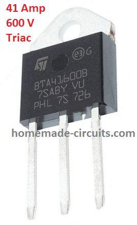
Controlling heaters rated as high as 1500 watt requires stringent specifications with the controlling unit for safe and effective implementation of the intended operations.
With the advent of advanced snubber-less Triacs and Diacs making heater controllers at massive watt levels has become relatively easier today.
Here we study a simple yet entirely suitable configuration which may be utilized for making a 1500 watts heater controller circuit.
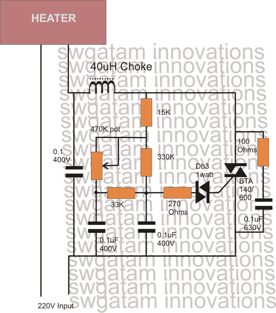
So I have explained the given circuit diagram with the following points:
How the Triac/Diac AC Controller Works
The set up of the circuit is pretty standard as the the wiring is very similar to the ones which are normally employed in ordinary light dimmer switch circuits.
The standard triac and diac set up can be seen for implementing the basic switching of the triac.
The diac is a device which switches current across itself only after a certain specified potential difference is reached across it.
The following network resistors and capacitors associated with the diac are chosen such that they allow the diac to fire only as long as the sine curve remains below a certain voltage level.
As soon as the sine curve crosses the above specified voltage level, the diac stops conducting and the triac is switched OFF.
Since the load or the heater in this case is connected in series with the triac, the load also switches OFF and ON in accordance with the triac.
The above conduction of the triac only for a specified section of the input sine voltage curve, results in an output across the triac which has the AC chopped into smaller sections, making the overall RMS of the resultant drop to a lower value, depending upon the values of the relevant resistors and capacitors around the diac.
The pot which is shown in the figure is used for controlling the heater element which initiates the above explained procedure.
The greater the resistance, the longer it takes or the capacitor to charge and discharge whih in turn prolongs the firing of the diac/triac pair.
This prolongation keeps the triac and the load switched OFF for a longer section of the AC sine curve which results correspondingly lower average voltage to the heater, and the heater temperature remains at the cooler side.
Conversely when the pot is adjusted toward to produce a lower resistance, the capacitor charge and discharge at a faster rate making the above cycle rapid which in turn keeps the average switching period of the triac at the higher side, resulting a higher average voltage to the heater.
The heater now generates more heat due to the increased average voltage developed across it via the triac.
Circuit Diagram
Parts List
Resistors 1/4 watt 5% CFR
- 15k = 1
- 330k = 1
- 33k = 1
- 270 ohms = 1
- 100 Ohms = 1
- Potentiometer 470k linear or 220k linear
Capacitors
- 0.1uF/250V = 2
- 0.1uF/630V = 2
Semiconductors
- DB-3 = 1
- Triac = BTA41/600
Inductor 40uH 30 amp (optional)
Controlling through Arduino Pwm
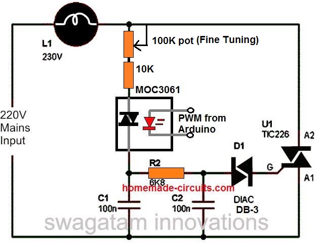
The above simple 220V dimmer switch control can be also effectively implemented using an external Arduino PWM feed through the simple method shown below:
Advanced Heater Controller with Snubber and RFI Elimination
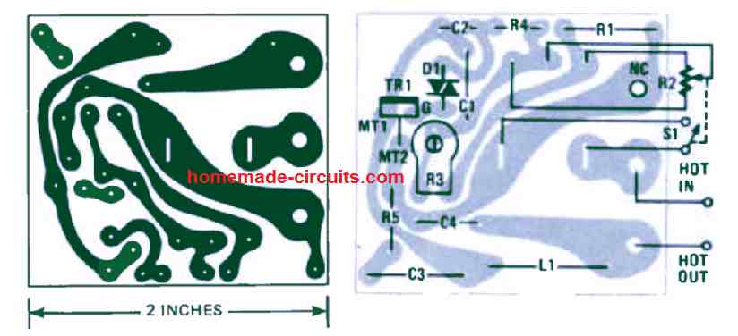
As soon as the voltage around C2 increases over approximately 30 volts (during any phase cycle), the Diac (D1) breaks over and produces a trigger pulse for the gate of the Triac (TR1).
This leads to the Triac switching ON and it applies the entire AC line voltage to the load hooked up to SO1.
Adjusting the potentiometer R2 varies the phase (timing) of the trigger pulses applied to the Triac and therefore modifies the average power level going to the heater load.
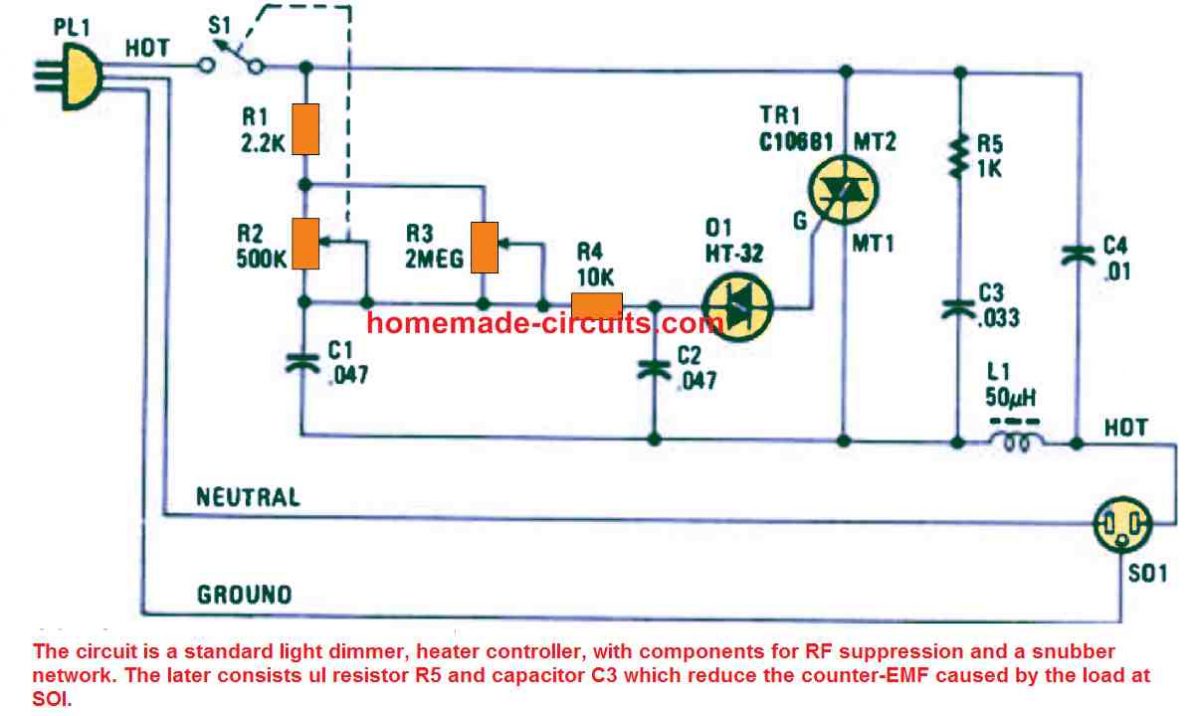
Resistor R5 along with the capacitor C3 works like a a snubber network over the Triac to safeguard it from the reverse EMF voltages spikes created by inductive loads every time the Triac is switched OFF.
Inductor L1, which is a 50 µH choke, and capacitor C4 are configured like an interference suppression filter, that enables the elimination of the RF noise commonly generated by this type of light dimmers or heater controllers.
The preset R3 adjusts the minimum starting range of the heater temperature, and helps the user to ensure that the power to the heater always starts from the minimum power when R2 is moved to the minimum position, and the heater gets maximum power when the R2 is moved to the maximum adjustment point.
PCB Design
1000 watt Light Dimmer
Nearly all light dimmers that you can get from the common electrical products stores can simply manage pretty small electric power.
A few hundred watts is normally the handling capacity. The straightforward dimmer circuit demonstrated below is designed to control a power as high as 1 kW.
There is nothing much to be explained regarding the details of the circuit.
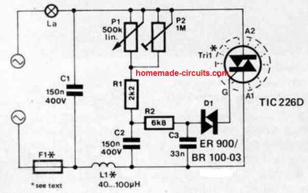
This high power light dimmer includes one triac, a single diac and an RC network where the period of the charging and discharging of capacitor C2 could be fixed using potentiometer P1.
Noise disturbances and transients are kept under control through capacitor C1 and the inductor L1.
How to Set up
Setting up of the circuit requires adjusting the pot P1 so that it reaches its maximum resistance, and then preset P2 must be tweaked until the attached lamp is just at the verge of shutting down.
In case a lamp higher than 100 W is utilized the triac should be attached to a heatsink having a heat transfer specification rate of about 6 °C/W.
When the circuit is used like a 1000 W dimmer, suppressor coil L1 should be rated to handle a current of 5 A with an inductance value that may be up to 40uH, while fuse F1 must be rated at 6.3 amps.
Heater using Transistors and Resistors
This unique heater circuit which involves transistors and resistors for the heat dissipation instead of a heater coil was designed by Mr. Norman, but he faced an issue with the circuit.
The problem and solution for the design can be understood from the following discussion:
Problem:
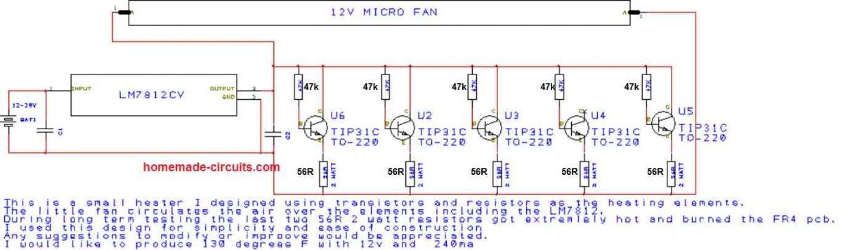
I designed a small heater using LM7812 voltage regulator and Tip31c transistors and resistors.
I tested it over several hours and found a problem. The last two 56R resistors got extremely hot and burned and scorched the pcb. I am attaching a schematic.
I couldn't find a similar project on your website, so I am trying to contact you through this contact point. Thanks!
The Solution:
That looks very strange because the 56 ohm resistors at the emitter of the transistors should force the transistor to dissipate the heat equally among the resistors and the transistors.
The last two 56 ohm resistors getting hotter means that the last two BJTs are conducting more freely than the remaining transistors.
The easiest way to tackle this problem is to mount all the transistors over a common aluminum strip, so that the transistor exchange their body dissipation uniformly with each other and thus all the transistors conduct and dissipate equally.


Questions & Answers
this circuit can use for as a 2000w motor dimmer swich?
yes, can be used.
No, you will have to make it.
use BTA04/600 triac
you can try other lower values such as 0.022, 0.033. 0.047, 0.068 etc
Hi
Tried your circuit and blown two triacs. Please confirm the connection of triac.
You say the centre connection should go to the capacitors but the data sheet shows the centre is T2 which the diagram shows connected to 15K & choke. Tested using 40watt bulb as a load and each time it flickered few times and the triac failed.
I am sorry, it should be the left lead (A1) which must join with the capacitor common rail while the center lead goes up and joins with the 40uH choke.
Thanks for the reply
Can't figure out what's wrong. The diac is not polarity sensitive.
no diacs are never polarized but here it should be a heavy duty type not the usual small blue colored ones, the right one would look quite like a 1N5402 diode.
try the circuit with the 200 watt lamp initially, once the dimming function is confirmed you can go ahead with the intended higher load
Thanks for reply
Can only find small coloured diac
Spec shows itrm=2A p=150mw
could this be the problem?
Any makers name part number etc
Thanks
You can try it out, probably use two of them in parallel with individual 100 ohm resistors, might just work.
Sir,
I want to make it for 2000 W water heater/Gyger, before construction I want to make clear some points
1. Resistances are used here — what are there wattage value
2. Capacitor are used here are of micro farad or nano farad?
3. How to arrange/make the inductor, if we omit this will circuit work ? what is the wattage value of inductor, if possible mention the range of inductor(from this value to this value) which will work,
4. Both diac and triac needs heat sink
regards,
Akash
Akash,
all the resistors can be 1/4 watt rated.
capacitors are all uF (microFarads)
Inductor may be built by winding around 100 turns of 1mm magnet wire over a 1cm diameter ferrite rod
only the triac would need a heatsink, not the diac.
Dear sir,
I have eurotherm TS200A temperature controller.this is thyrister based. This required 0-5V control voltage. I want one temperature control circuit when temperature is 25deg C the voltage is 0V. Temperature reduces the control voltage increase from 0-5V. Please provide the circuit diagram.
Thank you.
Dear Suresh, I'll try to post it soon in my blog.
Swagatam, Can this setup be used with 110v and 1500 watt element? What would need to be changed? The element I was thinking of is for a hot water heater. Thanks so much.
Kurt
Hi Kurt, yes it can be used with a 110V input, the 470k pot will need to be replaced with a 220k pot, that's all…rest can be as is
Swagatam, Thank you for your prompt answer. One further question. Is this considered a "Constant Current" controller? I guess a typical thermostat control has a range when it switches on or off, a sort of fluctuation range? Is this a stable control when set? Sorry for the basic questions. Thank you.
Kurt Kenyon
It can be considered as a constant voltage controller, and if the voltage is constant current will be also constant.
so, a fairly good consistency can be expected using this circuit in terms of power output to the load.
Sir, could you please tell me what changes are required in this circuit to make a heat controller circuit for about 500W-700W, 10-15A device powered from a DC source of 48V?
Sheri, you can try the following circuit:
https://www.homemade-circuits.com/2012/05/make-this-pwm-based-dc-motor-speed.html
just replace the fan with the heater system
Swagatam, I'm hoping you can help me out with this type of circuit. I'm not an electronics expert so reading most circuit diagrams are just confusing, but I'm trying to learn.
I would like to create this circuit but I need it to control a 1500 watt, 6.3 amp restive load heater via a MCU. I have to watch the heat and would like the circuit to be as small as can be. Can you help point me in the right direction? Maybe a circuit design a preschooler could figure out? 🙂 I would love it if I could also pull 5v dc for the MCU at the same time?
What I'll have available at the mains wall is the line that completes the circuit. I would like to not have to rewire the the line to the heater for this circuit. Crude drawing below to help, hopefully.
AC from wall –> to heater
++ = this would be the relay/power circuit to complete the circuit to turn on the heater.
+ = ground is tied straight thru to heater
(common) ——- (++) ———
AC Heater
(ground) ———–+———-
Thanks for the help,
I appreciate your interest John , however my knowledge regarding MCU programming is not great so it would be difficult for me to program the coeds for you, so I am sorry I won't be able to help you with this implementation.
…or if you think I did not understand your requirement, I would request you to explain it with more detail.
Thanks for the response, What I'm after is just the relay/power circuit that would have a pin that I could connect to the MCU, so I would raise the pin high and it would trigger the relay. I'm good with coding the MCU just not with electronics so trying to figure out your circuit and modify it for my heat requirements and adding a pin for control on/off is beyond my skill set. This would be something like the link below but of course better and with the requirements above.
https://www.sparkfun.com/products/10684
Thanks for the reply. I'm actually just looking for help with the circuit. I was hoping your design could be modified to have a pin that the MCU would connect to so it could trigger the relay on/off. I can code the MCU just can't design circuits.
Thanks
OK, then I think the following article would help you to solve your problem quickly, please refer to this:
https://www.homemade-circuits.com/2012/01/how-to-make-relay-driver-stage-in.html
In the above referred relay driver stage, the base of the transistor could be connected with the MCU trigger, for activating or deactivating the associated relay… this is what you were looking for, right?
That's a perfect start, thanks. Now, how do I integrate the relay driver with this circuit to drive the 1500 watt heater? Also, if it's possible, can I add to this circuit the ability to supply 5v DC to power the MCU?
Thanks for your time and help, I really appreciate it!
connect the relay pole to one of the AC inputs, it could be the phase or the neutral doesn't matter. connect the N/O contact with one of the input wires of the above circuit and let the other wire connect directly with the second mains supply input.
this will control the ON/OFF switching of the above circuit but the actual heat control can be implemented only through the given 470K pot
…the 5V could be derived from the 12V relay supply through a 7805 IC…and the 12V can be obtained from a 12V AC/DC adapter.
Not sure if my other post went thru, but thanks. That link is a good start. I had a S216S02 and built the relay driver for it. It's working but I'm sure it isn't going to handle the 1500 watt heater, or will it? I'm not sure how to finish this so it can. I can't quite make out the parts needed for you circuit or how to get the relay driver to work with it either. Your help with this is appreciated.
Thanks
yes I have answered your previous comment, I may be late but I normally never miss any.
the relay is supposed to be at least 20amp rated, such as this one:
the relay driver transistor should be a 2N2222 for handling this type of relay.
actually you should have explained the entire sequence of the required operation, so far you have mentioned it in bits and parts…if possible tell me the whole sequence then probably I'll be able to help you in a better way.
Sorry I wasn't that clear. Let me try this again. I'm asking for your help because your circuit here is close to what I would like.
I have a forced air heater that is rated at 1500 watts, 6.3 amps that I would like to control, on/off, with a MCU. It doesn't need any thermostat functions, I'll handle that via code. I don't have much room where the wiring is located in the wall so something small would be nice. An added bonus would be to combine a power AD/DC circuit into this design. I already have power, just need to convert it to DC. I don't what to have to run a AC/DC adapter for power as I don't have an outlet near the area I'll be accessing the power/wires for the heater.
I tried using a 25 amp SSR like this one http://www.ebay.com/bhp/ssr-25da but it failed. It got way too hot. I would rather not use a mechanical relay due to the clicking sound and the possible arcing of the relay. I also bought a 16 amp SSR but it gets too hot also. I read that the SSR should be twice the rating as the device it is controlling but I think I'm still missing something else to keep the circuit small and cool.
If this still isn't clear I can try again or if I'm asking for too much help I understand.
Thanks for your time and help.
From your explanation it appears that you intend to control the heater through some kind of predetermined algorithm through your MCU, that would periodically switch OFF and ON the heater and try to maintain the temp at the required level.
In that case the above circuit may be completely irrelevant to your need.
even the relay or the SSR won't be required.
You just have to feed your MCU trigger to a MOCxxx based circuit and enjoy a smooth implementation of the system.
Not sure what that is, but I'll do some googling. 🙂
Thanks for your time and help.
you are welcome 🙂
what componets should i replace to work this ckt for 2000W,10A heating load, and what r the names of diac triac and its rattings
you can use the same design that's shown above.
preferably use a 220k pot instead of the shown 470k
sir i have done it but i am not able to adjest variable resistor(heatis not regulating), and my 40uh is heating.what i should do??
first test it using a 200 watt bulb to ensure that everything is correctly done in your circuit…after that you can use the heater coil…make sure the triac is mounted on a heatsink
sir how to make 40uh chock??
don't use it… it's not important
Hi Sir,
What component/s should be replace to run this circuit with 4000 watts load/heat lamp.
Thank you!
Fritz, only the triac will need to be replaced with a BTA41/600V rest can be as is.
Hi I am very interested in this circuit
I wish to use it for a 5500 watt water heater. Would I be right in saying I would only have to upgrade the triac? And also what type heatsink would be appropriate? Thanks in advance
Hi, you can use the above circuit for your application, the same triac which is shown in the diagram can be used, or a BTA41/600V can also be tried, but make sure it is mounted on a large heatsink…..and also the diac should be rated to handle at least 100mA
Hi what kind of capacitors are these thanks
those are metalized polyester type or polypropylene (PPC) type will also do
https://www.homemade-circuits.com/2016/02/types-of-capacitors-explained.html
yes it will reduce power consumption proportionately as the intensity of the load is reduced