An inverter is an equipment which will convert a battery voltage or any DC (normally a high current) into a higher mains equivalent voltage (120V, or 220V), however unlike an UPS inverters may lack one feature, that is these may not be able to switch from mains battery charging mode to inverter mode and vice versa during grid power failure and restoration situations.
Converting an Inverter to UPS
An inverter can be easily converted to an UPS with a few simple modifications or rather additions with their existing circuitry.
The lacking or missing changeover feature in an inverter can be upgraded by including a few number of relay stages within its circuit, as explained in the following sections:
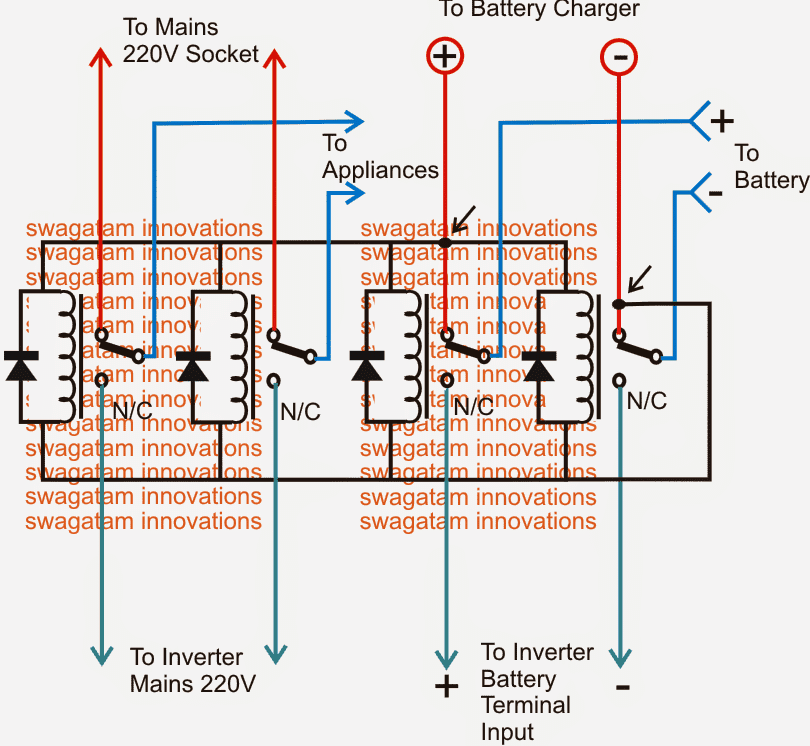
Referring to the figure below, we see that the above requirement is implemented by using 4 SPDT relays whose coils are wired up in parallel and joined with a mains operated DC source, which could very well be the battery charger DC output.
It means during the presence of mains input the relays would be energized such that their N/O contacts get connected with the individual relay poles and the respective electrical gadgets which could be seen connected with the poles..
The left two relays can be seen with their N/O contacts connected with the mains AC input, while the N/Cs are terminated with the inverter mains output.
The relays at the right side have their N/O contacts rigged with battery charger (+)/(-) inputs, and the N/Cs are integrated to the inverter DC input.
The above data ensures the following actions during mains presence and failure situations:
When mains AC is present, the appliances get connected to the available mains power via the left pair of relay poles, while the battery is able to get the required charging voltage through the right hand relay poles. This also ensures that the inverter is cut-off via the N/C points from the battery and is no longer able to operate.
In a situation when mains AC fails, the relay contacts revert to their N/C contacts, giving rise to the following actions:
The battery instantly gets connected with the inverter DC input via the right hand side relay N/C contacts, such that the inverter becomes operative and its output starts producing the required mains back up voltage.
At the same instant the above inverter mains voltage now gets switched to the appliances via the left hand side relay N/C contacts ensuring that the appliances do not experience an interruption while the positions revert in the course of the above actions.
Selecting the Relays
The relays must selected with low coil resistance type so that they operate under higher switching currents, and therefore are able to "hammer" the contacts much harder and quicker compared to the lower resistance coil relays.
This will ensure the changeover time to be rapid within milliseconds which happens to be the most crucial factor with UPSs and inverters needing to be converted into UPS systems.
In the above diagram if an automatic battery charger is used, the supply would be cut off once the battery is fully charged, which would also cut off the supply to the relays forcing the inverter to switch ON even while the mains is present.
To avoid this issue, the relays must be powered through a separate power supply as shown in the following diagram. A capacitive type of power supply circuit could be seen here, which makes the design much compact.
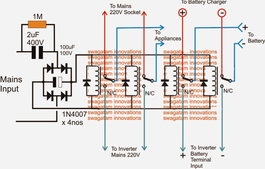
Note: Please connect a 1K resistor across the filter capacitor associated with the bridge rectifier, this is to ensure its quick discharging during a mains failure, and an instant switching of the relevant relays.
Main Components and Their Functions:
Bridge Rectifier (1N4007 x 4)
So we have this bridge rectifier that consists of four 1N4007 diodes and its main job is to take the alternating current (AC) from the mains and convert it into direct current (DC). This conversion is really important because we need that DC power to make the relays work properly.
Filter Capacitor (100uF/100V)
Next up we are looking at the filter capacitor 100uF rated for 100 volts. These capacitors are essential because they help smooth out the rectified DC voltage making it much more stable and reliable for our circuit.
Relay Coils
Now let us talk about the relay coils. These coils function like switches that allow us to toggle between using mains power and inverter power. They play a crucial role in controlling how our entire system operates.
Formulas and Calculations:
DC Voltage Across the Relay Coil
We can figure out the DC voltage across the relay coil using this formula:
Vdc = (Vrms * √2) - Vf
In this equation the Vrms represents the input mains AC voltage (for example we might say it is 220 volts) and Vf is the total forward voltage drop across the bridge diodes. For our 1N4007 diodes we can calculate that as
Vf = 2 * 0.7V = 1.4V.
If we do a quick calculation for a 220V mains input, it would look like this:
Vdc = (220 * √2) - 1.4
Vdc = 310.6 - 1.4
Vdc = 309.2V
Capacitor Selection (Ripple Voltage)
When it comes to selecting capacitors we need to think about ripple voltage which we can calculate using this formula:
ΔV = Iload / (f * C)
In this formula Iload is the load current drawn by the relay, f is the rectified AC frequency (which would be around 100 Hz if we are using a full-wave rectifier with a 50 Hz mains supply) and C represents the capacitance measured in Farads.
For example if we are working with a 100uF capacitor and our relay coil is drawing about 50mA of current then we can plug those values into our formula like this:
ΔV = 0.05 / (100 * 0.0001)
ΔV = 5V
Relay Coil Voltage
It is really important for us to ensure that the voltage rating of the relay coil matches up with the rectified DC voltage we calculated earlier. So if our rectified voltage is sitting at 309.2V then we need to make sure to use a relay that can handle that specific voltage.
Relay Switching Time
When we want to find out how quickly our relay can switch then we can use this formula:
ts = L / R
Here L stands for the inductance of the relay coil and R represents the coil resistance.
For instance if we have L = 50mH and R = 500 ohms then we can calculate it like this:
ts = 0.05 / 500
ts = 0.1ms
Current Limiting by a Capacitor in AC Circuits
The current limited by the 2uF/400V capacitor is given by the formula:
I = Vrms / Xc
Where:
- I = Current through the capacitor (in amperes)
- Vrms = Mains AC RMS voltage (e.g., 220V)
- Xc = Capacitive reactance of the capacitor (in ohms)
The capacitive reactance is calculated as:
Xc = 1 / (2 * π * f * C)
Where:
f = Frequency of the mains AC (e.g., 50 Hz)
C = Capacitance (in farads)
Step-by-Step Calculation
Calculate Xc (Capacitive Reactance):
Given:
C = 2uF = 2 × 10⁻⁶ F
f = 50 Hz
Formula: Xc = 1 / (2 * π * f * C)
Substitution: Xc = 1 / (2 * 3.1416 * 50 * 2 × 10-6)
Xc = 1 / (0.00062832)
Xc ≈ 1591 ohms
Calculate Current (I):
Given:
Vrms = 220V
Xc ≈ 1591 ohms
Formula: I = Vrms / Xc
Substitution: I = 220 / 1591 I ≈ 0.138 amperes (or 138mA)
Design Considerations:
As we design our circuit we need to make sure that the diodes are capable of handling both peak inverse voltage (which will be equal to Vpiv = Vdc) and also the current (which will be Ipeak = Iload).
We should also select a relay that has a sufficient contact rating so it can safely manage whatever load we connect to it.
Lastly do not forget about that 1M resistor, its job is to discharge the filter capacitors when we disconnect power to prevent any accidental shocks.



Questions & Answers
hi swagatam
your idea is very but i have little confusion that all relays are powered by charger. so there may be time lag for relay to denergise during power failure because charger contains large filtering capacitors.
Hi Jignesh, an smps normally carries a low value filter at the output, therefore with 4 relay coils in parallel, may be a 100uF or 220uF capacitor could take hardly any time to get discharged, so I don't think that would create any significant lag for the relays.
we can use low resistance relays (100 ohms) for further ensuring a quick response from them.
Hi, how does this circuit handle the fact that the AC mains and the mains from the inverter might be out of phase? What would appliances such as TV's do in a case where these phases are not alligned on the switch over?
Hi, this issue is not critical, even if there's a slight delay in the switching it won't harm the appliances in any manner….by the way TV sets work on DC, so anyway the phase angle doesn't make a difference
Hi Swangtam! your design is very great. i requst to please design a circuit of complete ups which operate only three energy saver light of 25watts. when ac present inverter should shutt off and battery get charge and during ac failure 3saver connected with this inverted luminate. i shall be very thankful to you.
Thanks Samar, I already have one design in this blog, you can check it out here:
https://www.homemade-circuits.com/2012/02/how-to-make-mini-homemade.html
Hi Swagatam I have 2 PC working on one inverter, distance between inverter and PC is around 4 meter, I have 2 UPS good condition but without batteries, can I connect these UPS to battery of inverter directly, will there be conflict amid charger of inverter and chargers of UPS, if yes how can stop charging from UPS to inverter battery.
Technically there shouldn't be any conflict between the two since their polarity would be at the same level. You can prefer to remove the inverter charger as that may be easier to locate than to locate the charger section of the UPS.
Or you can simply leave them as is, and use the battery as common with the two units.
Thanks Swagatam for clearing my doubt, another method I was thinking to put a diode before connecting UPS with battery, so there is no current to battery from UPS. If it is possible can I use IN007 (small diodes plenty available from old CFL ) may be 10 diode in parallel
Yes you can block one of the inputs through a diode, but 1N4007 will not work, even in parallel, because diodes cannot be connected in parallel.,,,you may have to opt for a special 10amp diode…
Godd Evening Sir.
Sir, I want use this circuit as changeover and inverter switch.
I have built the circuit, but I used only three relay as above and the design is as follows:
*the first two relay are remain as it's on the circuit above.
*the third relay is used as a swicth between the inverter and the battery.
The positive ( ) were of the battery is placed in NC and the center were of the transfo is connected to the POLE of the relay.
Sir, I hope there is no problem with this desing. And I hope the relay can hold the current between the center were of the transfo and the positive terminal of the battery.
Thank you Sir.
Hi Aminu, if you do everything correctly then definitely it will work as explained in the article.
the relay contact current rating should be much above the current consumption of the transformer, to work handle it safely
Sir,
Both the relay and the transfo are removed from the same UPS.
then it's fine, you can use them together
Sir, I did it, and it works very fine.
Still I want to know what current of relay can handle 200 AH battery?
Thanks for the help sir.
Aminu, you can use a 30amp relay for that
Sir you are great!
and Iam greatful for the help.
Sir, can we charge 200Ah battery with transformarless charger circuit?
thank you once again.
It's my pleasure Aminu…
if the transformerless adapter is rated at 20 amps then yes it is possible.
Ok Sir.
Thank you very much.
Sir, do you have a circuit on transformaless as above that can charge 200Ah 12v battery?
thanks a lot Sir.
I am sorry Aminu, I do not have a 20 amp smps at the moment, but if I find one will surely post it here for you.
Ok, Sir.
Thank you.
Sir, can I get one that can safely charge 50Ah to below. like 40Ah, and or 20Ah.
thank you sir.
Thanks Aminu, I have a 12V, 5amp smps circuit posted in this blog you can try that for your requirement.
can I use DPDT 220v relay??
yes you can…
Hello… Sir, if I connect only one relay (12 volt,200 ohm) on the above change over circuit.then,what is the changes on circuit.
hello swapan, for a single relay the specifications should be 4 pole 4 throw type…that is it must have a 4 sets of N/C an N/O contacts and 4 central poles.
sir, if i use dpdt 8 pin relay to change the mode, then one relay can change load from mains to inverter and another one relay(8 pin) can separate battery from charging mode to inverter battery terminal input, when main is out.so, please tell about correction to me.
Hi Swapan, yes you can use two DPDT relays for achieving the same results.
Hello sir. I would like to make a 12volt DC battery backup system to run 6 Led light each 12v 12wats and one 12v dc fan during power failure.i have 2 sealed lead acid batery each 12v 7Ah. Please guid me how to make this and i need to maintain battery by charging and without over discharge. Sorry for bad english.
hello, you can try the following circuit, this is full fledged emergency lamp circuit with max features:
https://www.homemade-circuits.com/2015/10/smart-emergency-lamp-circuit-with.html
Hi Swagatam,
Your blog makes interesting reading, and your knowledge seems to be phenomenal. I would like an 'idiots guide' to convert my inverter into an 'online' ups. I am not very technically savvy, but can manage my way around circuits – somewhat. I have an inverter for my house. It has two batteries of 500W each, I think. There is this delay in the inverter coming on once the mains fail. I was thinking of buying a new online one, but came across your blog. Would it be possible for me to make an add-on unit that I can use with the existing inverter? Or do I have to tinker with the existing circuitry – which I do not want to do. Some advice would be very welcome.
Thanks,
Yogi Bhattacharya
Thank you Yogendra, you will have to modify the existing inverter system by opening it and by checking the specific stages.
You will have to check the relay changeover section and remove the capacitor which may be causing the delay in its operation….once you do this you will be able to find the inverter switching much quicker and making an instant changeover from mains to battery and vice versa.
Thanks a lot, will attempt to do this. Will revert in case I need your assistance.
Sir I need your assistence.
I have a Fan removed from dead Air Conditioner I what use it as a room fan but, it fails to work with cieling fan regulator.
Is there any circuit to achieve this?
Thank you Sir.
Aminu, both the motors are "capacitor-start" type however Air Cond motors are more powerful and include a relay,
first keep the dimmer at max speed let the motor start and then you can try reducing the speed once the relay has clicked.
Sir, the normal regulator operate Air Cond fan only at number one, which is the highest among the change. if an attampt is made to reduce the speed, the fan goes off.
sorry, can't say without checking the motor practically.
Hello Swagatam ,
I have an 5.5kva microtek Inverter which i use to power my cyber cafe.The issue i am facing is as soon as the electricity trips or even fluctuates , a few of my computers goes off automatically although all the pc's have there own UPS (most of them are new or with new replaced batteries). Kindly help
Hello Sameer, PCs are generally very sensitive to power fluctuations and even the slightest of power lapses can rattle them…in your case it could be happening due to may be slight inefficiency with the relay changeover actions within the UPSs, which could be difficult to correct or avoid. You can try replacing the systems with SSR based UPSs or alternatively you can try replacing the relays with SSRs after doing some research in the field….
hi sir. please I need a circuit of automatic fan that will cool my heatsink when it get hot.. the fan will automatically blowing when it cool it will stop blow. ..
chucks, you can try this
https://www.homemade-circuits.com/2015/03/fan-speed-controller-for-heatsink.html
Passing inverter battery power via a relay could be a very bad thing considering the fact that the inverter could be drawings up to 90amps from the battery and if the really is rated 20-30a it could mess things up
In electronics Everything can be bad and dangerous if done non-technically, a 30 amp relay would burn and fuse at 90amp any sensible person will understand this.
thanks a lot let me take time to build one and incorporate it to my inverter
have a blessed day sir
you are welcome Olupot
Sir what is the relays specifications??
It will depnd on the UPS wattage, for 200 watt and below, you can use ordinary 12V/400 ohm/5 amp relays
ok sir, that mean i can use 12v 10amp relay for 400 watt inverter ???
actually if you divide 400 by 220 it gives 1.8, that means even a 5 amp relay would work…
ok sir, another confused in the place were u wrote TO MAIN 220V SOCKET, and second place you wrote TO MAIN. my question is that which one will go to the MAIN AC GRID??
Mains socket is Mains Grid…both are one and the same…the transformerless power supply input will also connect with this mains 220V
woow!! that is Good i really appreciate sir.
Good morning Sir this is my second agenda circuit i want to built it and i will let you know if i am finished and if i hv problem also
OK will do, wish you all the best!
I am now seeing the comment box thank you very much Sir
yes, may be the problem was with the new theme, I have replaced it with the original one.
That is very Good and we really appreciate that.
Good mprning Sir as i told u last time that i wanted to do this circuit. but i want know if it does not delay before changeover take place. what i mean is that can this circuit change the phase very fast without any interrupt
Hi Bashir, the delay will depend on the relay specifications and quality.
A High quality relay will give minimum response time, however for this the supply source will also need to be from an SMPS based high current power supply.
Good afternoon Sir, Sir i didn’t get 2uf 400v can i substitute it with 2.2uf 400v?? and 100uf 100v with 100uf 160v???
Hi Bashir, no problems it will work, however make sure the total current of the relays are not above 80mA, otherwise you may have to use a 4uF capacitor.
Sir i will try and find the 4uf because my relay is 12v 10A. that mean i can’t used with 2.2uf
Bashir, 10A is for the contact rating, please check the coil resistance…it should be above 300 ohms
exactly!! it is 400 ohms
then it is OK to use 4uF
ok no problem i will do that
Good morning Sir, can i make this circuit with 24v relay??
Yes you can use 24V relay also…that will be more efficient than 12V relay
Good evening sir you said that we should put 1k resistor across the filter capacotor. Do you mean we should put it between the positive side and the negative side of the capacitor???
Yes across the capacitor, or you can also put it across the supply rails
Good evening Sir i am finished with this circuit but the 4UF capacior as you directe me to use is getting very hot the more i connect the circuit on 220v ????
Engr bashir, make sure the capacitor voltage is 400V. I think there may be some problem with your capacitor, otherwise a high voltage capacitor will never become. Try Replacing it with a good quality PPC or MKT capacitor and check again
Sir can u provide me rating of o/p transformer & can we get it in market
Uday, you can use any step down transformer rated at 10 amp, and voltage depending on your battery voltage
Good day sir, is about this change over circuit, pls clear this few questions. 1.the relay must be selected with the low coil resistances type so that they operate under higher switching current pls explain what you mean, and how will I select relay by amps and ohm’s that will do the job and intense of higher current does it mean that 220v from NEPA is not higher current that can switch these relay. 2. the two N/C at the down right side that you indicate as ” to inverter battery terminal input”? I want to know if it is the battery (+) (-) terminal from my ic circuit. 3. the upper right hand side that you indicate as “(+)(-) battery charger”? now what about the input of the charger will it be connected to the 220v main socket. 4. I have manual change over and this is how it been operated, NEPA is at the upper side which is the main, my load which is the appliances is in the middle and the generator is at the lower down side, when there is No NEPA I will push my load down to generator before switching the Gene on. so after building this your change over circuit my load will be permanently on NEPA side and your circuit will be doing the changing automatically am I right if not correct me.
Youngking, low coil resistance is preferred so that the the contacts are pulled with greater speed and the changeover time is faster. That’s all there’s no other critical thing about it! You can use any relay if a few millisecond delay in the changeover is not important for you.
The bottom right +/- will go to the inverter supply +/- points, where normally the battery supply is connected.
This changeover is designed for mains to inverter change over, I am not sure about generator, because generator starter system has a different procedure!
sir from 600 watts inverter up how will one select relay to be use .sorry for too much question
What is the battery specifications?
my battery specification is 12v 75 amps
You can use a 30 amp relay for this.
I appreciate thanks a lot
Hello Sir. I have an inverter setup of 3kva with sg3524 based oscillator.
My transformer has a tap for charging.
Do you have a setup for automatic charging and changeover using the mosfets stage and not requiring an extra charger?
Hakeem, that may require many relays and a complex set up, so better to use a small separate charger with the above relay connections, or you can use a single transformer set up as explained in the following concept
https://www.homemade-circuits.com/500-watt-inverter-circuit-with-battery-charger/
Do you have a 24v charger circuit that can charge up to 200 amp 24v battery or 2 12v 200a batteries?
You can try the following concept for your requirement, it should work
https://www.homemade-circuits.com/make-this-48v-automatic-battery-charger/
I really enjoy your circuits it very easy to understand. I have been stock to design this types of circuit but i hv problem but now am free thanks i will start it over again from where i stopped.
Hello Swagatam.
Please can I connect a 40Ah LiFePo4 battery to use with a Bluegate 1200VA UPS??
Hi Ighodaro,
yes you can but the output will be restricted only to 200 watts max.
why a transfer switch? make an online ups so that the loads always run from inverter. this always conditions the incoming power.
transfer switch is much easier than converting to online type. If you have a quick, and cheap way of doing it, you can provide the idea here, will appreciate it.
incoming ac power, step down transformer, full wave bridge rectifier, voltage controlled relay to prevent overcharging, battery (with surge capacitors), inverter.
That is correct, but putting a few relays looks much easier and cheaper for the conversion.
Hi,
I have a Microtek 3.5kva jumbo Inverter which has 5 computers & 4 fans attached to it,
Problem is only at the time of power failure the desktops trip . Is it possible to attached the above circuit to make it work online so that the systems do not trip.
Also will it be possible for you to make such for me.
Regards.
Rajesh Kumar
Hi, yes it is definitely possible to convert your inverter into UPS, however, the relay may take some fraction of second to activate and deactivate, so I am not sure if the computer would be able to hold during those millisecond gap.
Hi swag good job you doing Sir i have a problem with inverter circuit with ic tl494 and irf3205 i completed to build and carried out tests it gives fluctuating frequencies from 40hz to 60hz sometimes to 100hz. frequency doesn’t stablise and one side of the transistor heats up when frequency hikes the dmm meter cannot read the ac volt instead it blinks you may advise me on the problem how to go about the circuit thank you
Thank you Julius, did you feed the DC supply to the TL494 through a stabilizer circuit?
You can refer to the following example and replicate the RLC filter/stabilizer circuit that’s been used here to feed the TL494 IC supply pins
Hi Sir, I have make a diagram on inverter which is the power supply form battery. But now I don’t know how to make or connect the above diagram to the diagram that i had done. which is you had mention on this page. Like more detail wiring or diagram that connect to battery. in my diagram, there are, mosfet, diode, resistor, preset, ic4047 (which power by battery). I’m very new to this and like to learn on it.
Where do you mean 1k resistor should be
It should be connected parallel to the filter capacitor between the bridge rectifier.
And can I use a solar (charge controller) to connect in the part of + and – part that u have said to battery charge controller