In an H-bridge inverter, we normally use a transformer to convert the input power into the required output voltage. But sometimes instead of using one big ferrite transformer, we may want to use two, three, four, or even more small ferrite transformers.
In this type of arrangement, all the primary windings are connected in series across the H-bridge output.
But is this connection possible? How do we calculate the current through the transformers? How many primary and secondary turns will be required? And how much total output power can we get from the circuit?
Let us understand these things with some simple calculations.
We will use the letter "n" to represent the number of transformers. So whether we use two transformers or five transformers, the same basic method can be used for the calculations.
However we must remember one important thing. Connecting more transformers in series does not automatically increase the output power. The total power still depends on the input supply, transformer design, and circuit efficiency.
How are the transformers connected in series?
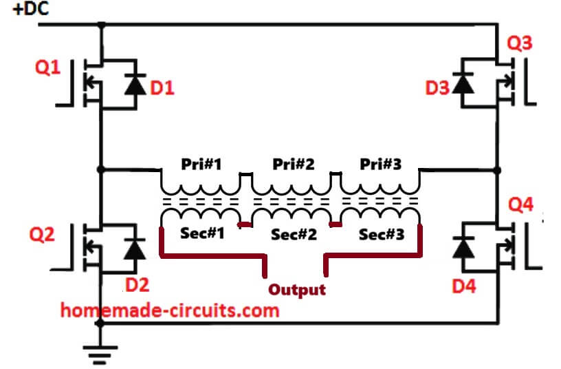
In an H-bridge inverter, four switching devices are used to produce an alternating voltage across the load. Now instead of connecting only one transformer primary across the H-bridge output, we can connect multiple primary windings in series.
For example, the connection can be made like this:
H-bridge output to Primary 1, Primary 2, Primary 3, Primary 4, finally to H-bridge return.
Here four transformers are used, but we can use any suitable number of transformers. The main point is that all the primary windings are connected in one series path. Because of this, the same instantaneous current flows through every primary winding.
Therefore:
Ip1 = Ip2 = Ip3 = ... = Ipn
Here Ip is the primary current, and n is the number of transformers.
But there is one thing we must understand. Even though the current is the same, the voltage across each primary winding may not be the same. If the transformers are properly matched and designed for equal voltage sharing, the voltage may divide approximately equally. But we cannot assume this will always happen.
The voltage across each primary must be checked because an excessive voltage can cause the corresponding ferrite core to saturate.
How to calculate the input power
First we need to know how much power is available from the DC supply.
The formula is:
Pin = Vin × Iin
Here:
- Pin is the input power in watts.
- Vin is the DC input voltage.
- Iin is the average current drawn from the DC supply.
For example suppose we have a 12V battery and the inverter draws 50A from it.
Then:
Pin = 12 × 50
Pin = 600 watts.
So the inverter receives 600 watts from the battery. This is the total input power available for the switching circuit, transformers, and other components. But remember, the 50A battery current does not automatically mean that the RMS current through every transformer primary will also be 50A. The actual primary current depends on the switching operation and the load connected to the secondary windings.
How to calculate the output power
The inverter will have some power losses in the MOSFETs, transformers, rectifiers, and other components. So the output power will always be lower than the input power. We can calculate the approximate output power using this formula:
Pout = Vin × Iin × Efficiency
Here, efficiency must be written as a decimal. For example, 90% efficiency means 0.90. Let us take the same example:
- Input voltage = 12V
- Input current = 50A
- Assumed efficiency = 90%
Therefore:
- Pout = 12 × 50 × 0.90
- Pout = 540 watts.
So the estimated output power will be 540 watts. Some more examples are given below.
| Efficiency | Estimated output power |
|---|---|
| 80% | 480W |
| 85% | 510W |
| 90% | 540W |
| 95% | 570W |
These are only calculation examples. The actual efficiency will depend on the complete circuit and transformer design. Also using more transformers does not mean that the output power will automatically increase. If the input supply provides only 600W, we cannot expect 1000W of continuous output power from it.
How to calculate the voltage across each primary
Suppose we connect four transformer primaries in series across an H-bridge output. If the total voltage is 48V during one active half-cycle, we may initially assume that each primary receives one-fourth of this voltage.
The formula is:
Vp ≈ Vbridge / n
Here:
Vp is the approximate voltage across each primary. Vbridge is the voltage applied across the complete series-connected primary circuit.
n is the number of transformers.
Let us calculate this for different numbers of transformers. If we use two transformers:
- Vp ≈ 48 / 2
- Vp ≈ 24V.
If we use three transformers:
- Vp ≈ 48 / 3
- Vp ≈ 16V.
If we use four transformers:
- Vp ≈ 48 / 4
- Vp ≈ 12V.
If we use six transformers, then:
- Vp ≈ 48 / 6
- Vp ≈ 8V.
We can see that the estimated voltage across each primary becomes lower as we increase the number of transformers.
But this calculation assumes equal voltage sharing. In a real circuit, the voltage may divide differently because of differences in the transformers, their loads, and their electrical characteristics. Therefore we must check the actual voltage across each primary before running the inverter at full power.
How to calculate the primary turns
The primary turns are very important in a ferrite transformer.
If we use too few primary turns, the ferrite core may saturate. When this happens, the primary current can rise very quickly and damage the MOSFETs.
For a symmetrical square-wave voltage applied to the primary, we can use this formula:
Np ≥ Vp / (4 × f × Bmax × Ae)
Here:
- Np is the number of primary turns.
- Vp is the voltage across one primary winding.
- f is the switching frequency in hertz.
- Bmax is the selected maximum flux density in tesla (1 Tesla = 10,000 Gauss).
Ae is the effective cross-sectional area of the ferrite core in square metres.
This formula is for a symmetrical square-wave drive with equal positive and negative volt-seconds. If the switching waveform or duty cycle is different, the calculation must be adjusted accordingly.
Solved example
Suppose we have four ferrite transformers connected in series across a 48V H-bridge output.
Assuming equal voltage sharing, the voltage across each primary will be:
- Vp = 48 / 4
- Vp = 12V.
- Now let us use the following values:
- Primary voltage = 12V
- Switching frequency = 50kHz
- Selected maximum flux density = 0.15T
- Core cross-sectional area = 100mm².
First, we convert the core area into square metres.
- Ae = 100 × 10⁻⁶
- Ae = 0.0001m².
Now we put these values into the formula:
- Np ≥ 12 / (4 × 50000 × 0.15 × 0.0001)
- Np ≥ 12 / 3
- Np ≥ 4 turns.
So the calculation gives four primary turns.
However we should not select the turns blindly from this result. The core material, temperature, core losses, actual voltage waveform, and voltage-sharing conditions must also be checked.
In a practical design, we may need to use more turns to keep the core flux density within a safe limit. Also if the voltage across one transformer is higher than expected, we must calculate the turns for that higher voltage.
General primary turns formula for any number of transformers
We can use the same formula whether we connect two, three, four, or more transformers.
If the voltage is shared equally, then:
- Vp ≈ Vbridge / n
- Putting this into the primary turns formula gives:
- Np ≥ Vbridge / (4 × n × f × Bmax × Ae)
Here, n is the number of transformers.
This formula is useful for making an initial calculation. But it works only when the voltage across each primary is approximately equal and the other assumptions of the square-wave equation are satisfied.
If the transformers have different core sizes or the voltage is not shared equally, we must calculate the turns separately for each transformer.
For each transformer, we should use its actual maximum primary voltage and its own core area.
How to calculate the secondary turns
Once we know the primary turns, we can calculate the secondary turns using the transformer turns ratio.
The formula is:
- Ns / Np = Vs / Vp
- Or:
- Ns = Np × Vs / Vp
Here:
- Ns is the number of secondary turns.
- Np is the number of primary turns.
- Vs is the required secondary voltage.
- Vp is the primary voltage.
Solved example
Suppose one transformer has:
- Primary voltage = 12V
- Primary turns = 4
- Required secondary voltage = 36V.
- Now:
- Ns = 4 × 36 / 12
- Ns = 12 turns.
So the primary will have 4 turns and the secondary will have 12 turns.
The turns ratio is 1:3.
Ideally when 12V is applied across the 4-turn primary, the secondary will produce 36V. In the actual circuit, the voltage may be somewhat different because of transformer losses, leakage inductance, rectifier drops, and loading.
If we need DC output, we must also consider the rectifier and filter circuit. Each transformer must be calculated according to the voltage applied to its own primary and the required secondary voltage.
How to calculate the primary current
This is another important part of the design. As explained earlier, the same instantaneous current flows through all the series-connected primary windings.
Therefore:
Ip1 = Ip2 = Ip3 = ... = Ipn.
But we cannot calculate the actual primary current from the DC input current alone.
For example, if the battery current is 50A, it does not automatically mean that the transformer primary current will be exactly 50A RMS. The primary current depends on the power being transferred, transformer turns ratios, magnetizing current, switching waveform, and the load.
For an ideal transformer, the current relationship is:
- Ip / Is = Ns / Np
- We can also write:
- Is = Ip × Np / Ns
Here:
- Ip is the primary load-current component.
- Is is the secondary load current.
- Np is the number of primary turns.
- Ns is the number of secondary turns.
Solved example
Suppose a transformer has:
- Primary turns = 4
- Secondary turns = 12
- Primary load-current component = 15A.
- Then:
- Is = 15 × 4 / 12
- Is = 5A.
So the corresponding ideal secondary load current is 5A. This is only an example to explain the turns ratio. It does not mean that a 12V battery drawing 50A will automatically produce 15A in the primary winding.
The actual current must be calculated from the complete inverter circuit.
Also the primary winding carries magnetizing current in addition to the current associated with the transferred load power. Therefore, the actual RMS current may differ from the simplified calculation.
Do adding more transformers increase the current capacity?
Not automatically. When we connect several primary windings in series, then same instantaneous current flows through all of them. For example if the primary current is 20A RMS, every primary winding carries 20A RMS.
Therefore:
Ip1 = Ip2 = Ip3 = ... = Ipn = 20A RMS.
Each primary winding must be designed to handle this current safely. We must select the copper wire according to the current, winding space, temperature rise, and operating frequency.
At 50kHz, skin effect and proximity effect can increase the AC resistance of the winding. So, simply selecting thick wire without checking these effects may not give the expected result.
The current rating of the MOSFETs and other components must also be suitable for the actual current waveform.
How to calculate the power handled by each transformer
If all the transformers share the output power equally, we can estimate the power handled by each transformer using:
Ptransformer ≈ Pout,total / n
Here:
Pout,total is the total output power.
n is the number of transformers.
Solved example
Suppose the inverter delivers 800W of total output power.
If we use two transformers, then:
- Ptransformer ≈ 800 / 2
- Ptransformer ≈ 400W.
- If we use four transformers:
- Ptransformer ≈ 800 / 4
- Ptransformer ≈ 200W.
If we use five transformers, then:
- Ptransformer ≈ 800 / 5
- Ptransformer ≈ 160W.
The results are shown below.
| Number of transformers | Total output power | Power per transformer |
|---|---|---|
| 2 | 800W | 400W |
| 3 | 800W | 266.7W |
| 4 | 800W | 200W |
| 5 | 800W | 160W |
This calculation assumes that all the transformers share the power equally. In practice the power sharing depends on the transformer design, secondary connections, load conditions, and losses.
Also we cannot simply add more transformers and expect the output power to increase. The input supply and the complete circuit must be capable of providing the required power.
What if every transformer has a separate secondary output?
We can give each transformer its own secondary winding, rectifier, and load. For example, suppose we use four transformers, and each transformer supplies a separate 24V DC output. If each output delivers 100W, the current from each output will be:
- Iout = Pout / Vout
- Iout = 100 / 24
- Iout ≈ 4.17A.
The total output power will be:
- Pout,total = 4 × 100
- Pout,total = 400W.
So the four outputs together provide 400W. But the transformers must be capable of transferring this power, and the H-bridge must be designed for the combined load.
Also changing the load on one secondary can affect the voltage distribution across the series-connected primaries. Therefore, we must check the operation of the complete circuit with the intended loads connected.
What if the secondary windings are connected in series?
We can also connect the secondary windings in series if we need a higher output voltage. For example, suppose we have three secondary windings, each producing 24V under the same operating conditions. If we connect them in series with the correct polarity:
- Vtotal = V1 + V2 + V3
- Vtotal = 24 + 24 + 24
- Vtotal = 72V.
So the combined voltage will be approximately 72V under the assumed conditions. However, the output current will be limited by the current rating of the series-connected windings. The output power will still depend on the input power and the ratings of the transformers and other components.
We must also check that the winding insulation can safely withstand the resulting voltages.
What if the secondary windings are connected in parallel?
Parallel connection can be useful when we need more output current at the same voltage. But we cannot simply connect the secondary windings together without checking them.
Their output voltages, turns ratios, polarity, and electrical characteristics must be suitably matched. Otherwise, circulating currents may flow between the windings, or one transformer may carry more current than the others. In some designs, separate rectifiers or suitable current-sharing arrangements are used to avoid these problems.
The correct connection depends on the required output voltage and current.
Important Winding Polarity Instructions:
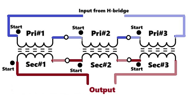
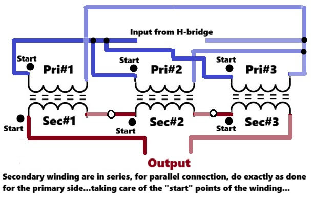
Remember, while connecting the primary and secondary winding in series or parallel, make sure to first confirm its winding polarity. Meaning, always remember the "start" wire of the winding, and make sure to do the connections as per this "start" point of the winding for all the transformers.
What should we check when operating at 50kHz?
The switching frequency is important for selecting the transformer turns and ferrite core. But frequency alone does not tell us how much power the transformer can handle. At 50kHz, we must check the following points.
Ferrite core losses
The ferrite material must be suitable for the operating frequency and flux density. The core can become hot if its losses are too high.
Copper losses
The transformer windings have resistance, and current flowing through them produces heat.
The basic formula is:
Pcu = Irms² × R
Here:
- Pcu is the copper loss.
- Irms is the RMS winding current.
- R is the winding resistance.
For example, suppose the RMS current is 20A and the winding resistance is 0.02 ohm.
Then:
- Pcu = 20² × 0.02
- Pcu = 8W.
So the winding will produce 8W of heat from its resistance under these assumptions.
At 50kHz, the actual AC resistance may be higher because of skin effect and proximity effect.
MOSFET losses
The MOSFETs must be selected according to the input voltage, current, switching frequency, and heat dissipation requirements.
Core saturation
The primary turns must be sufficient for the maximum voltage applied to each primary. If the core saturates, the current can rise sharply and damage the switching devices.
Temperature
We must check the temperature of the transformer cores, windings, MOSFETs, and rectifiers under the intended load. These checks are necessary before operating the inverter continuously at full power.
A high-current inverter can cause serious damage if a transformer saturates or a MOSFET fails. The circuit should be tested with suitable current limiting and properly rated measurement equipment.
Quick reference: All the important formulas
Here are the main formulas together for easy reference.
Input power
Pin = Vin × Iin
Approximate output power
Pout ≈ Vin × Iin × η
Approximate voltage across each primary, assuming equal sharing
Vp ≈ Vbridge / n
Primary turns for a symmetrical bipolar square wave
Np ≥ Vp / (4 × f × Bmax × Ae)
Secondary turns
Ns = Np × Vs / Vp
Ideal transformer current relationship
Ip / Is = Ns / Np
Copper loss
Pcu = Irms² × R
Total output power
Pout,total = Pout1 + Pout2 + ... + Poutn
Approximate power per transformer, assuming equal sharing
Ptransformer ≈ Pout,total / n
Here, n represents the number of transformers connected in series.
These formulas give us a starting point for the calculations. The final design must still be checked according to the actual switching waveform, core specifications, winding currents, and operating conditions.
Conclusion
So we can connect two, three, four, or more ferrite transformer primary windings in series across an H-bridge inverter, provided the transformers are designed to work together.
The same instantaneous current flows through all the primary windings. But the voltage across each primary is not always equal, and adding more transformers does not automatically increase the total output power.
We must calculate the primary turns according to the voltage across each winding, switching frequency, core area, and selected flux density. After that, we can calculate the secondary turns using the required output voltage. The total output power will depend on the input supply, circuit efficiency, and the power that the complete transformer assembly can handle.
Finally we must check the actual voltage across each primary, the current waveform, and the temperature of the transformers before running the inverter at full load.


Need Help? Please Leave a Comment! We value your input—Kindly keep it relevant to the above topic!