If you search for LED chaser circuits online, almost all of them show one single LED lighting up and moving across a line. That classic effect looks fine but if you flip the logic around, then you get something way more interesting, which is a running dark dot chaser effect.
Instead of one glowing light moving through darkness, here all the LEDs remain turned ON together all the time, and just one single unlit "dark" spot keeps moving step by step across the whole row.
Works with just Two ICs: IC 4017 and IC 555
You don't need any microcontrollers, programming, or extra logic gate ICs to build this. We just use the standard 555 timer and 4017 decade counter. But the trick is that, we simply connect the LEDs oppositely, in a clever current-sinking way so the 4017 turns OFF each LED when its output pin goes HIGH.
Let's look at the simple circuit schematic, how this reverse trick works under the hood, and how you can assemble it on a breadboard.
How it Works
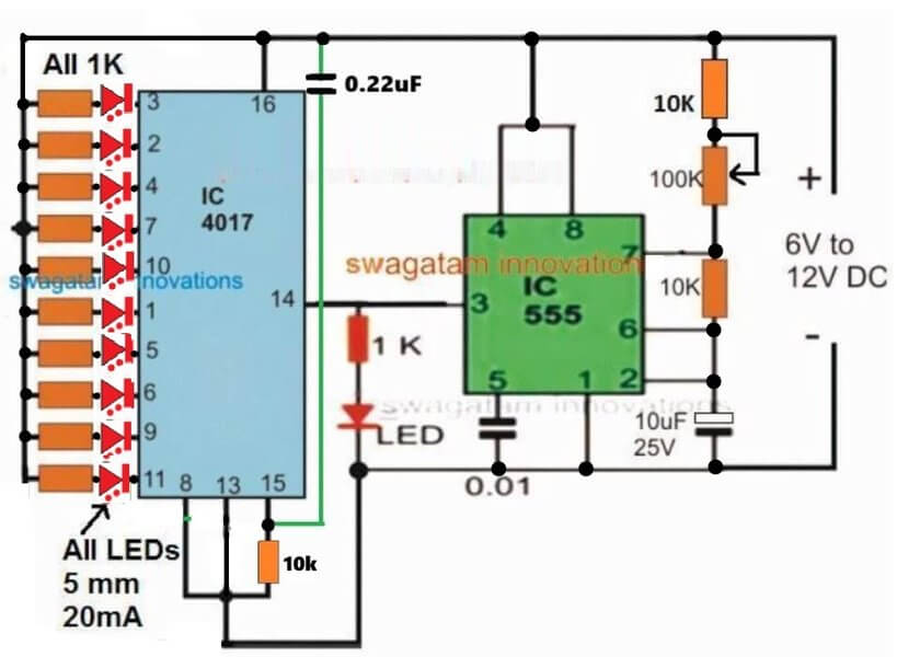
See, the 555 timer on the right side is still working as the clock generator. It generates square wave pulses using the 10k resistors, 100k pot, and 10uf capacitor.
Turning that 100k pot changes the speed of the output clock coming out from pin 3. That clock pulse from pin 3 feeds directly into pin 14 of the cd4017 ic.
Now here is the main trick for the running dark dot effect:look at the LED connections on the left. All the anodes of the ten leds are connected to the positive supply rail through their individual 1k resistors. And their cathodes are connected directly to the output pins of the 4017 ic (pins 3, 2, 4, 7, 10, 1, 5, 6, 9, and 11).
Normally, the inactive output pins of the cd4017 stay low. Because those pins are low (ground level), current flows from the positive rail, through the 1k resistors, through the leds, and sinks into these low output pins. So all nine inactive LEDs stay fully turned on!
But when the clock ticks, the 4017 turns one output pin high at a time in sequence. When a specific pin goes high (near supply voltage), the voltage on both sides of that particular LED becomes equal (positive supply on anode, high logic on cathode).
So no current can flow through that LED, and it turns off! As the 555 clock keeps pulsing, the high logic shifts sequentially from pin 3 to 2 to 4 all the way down to pin 11.
This turns off one LED at a time while the remaining nine leds remain on, creating that cool running dark dot effect moving across the LED bar.
How to Build
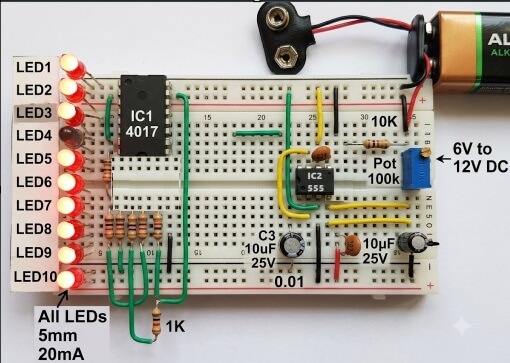
Gather your parts first: 555 IC, CD4017 IC, 10 LEDs, ten 1k resistors, two 10k resistors, 100k pot, 10uF cap, 0.22uF cap, 0.01uF cap, and a 6V-12V power supply.
Press the 555 IC into your breadboard. Hook up pin 8 and pin 4 to positive rail, and pin 1 to ground.
Wire the 555 clock section... 10k resistor from positive to pin 7, 100k pot between pin 7 and 6, another 10k resistor from pin 6 to 2, then bridge pin 6 straight to pin 2. Put the 10uF cap from pin 2 to ground, and 0.01uF cap from pin 5 to ground.
Insert the CD4017 IC. Then connect pin 16 to positive, put a 0.22uF cap from positive to ground, ground pins 8 and 13 and pull pin 15 to ground with a 10k resistor.
Connect a jumper from 555 pin 3 to CD4017 pin 14 to send the clock pulses.
For the dark dot effect, connect one side of ten 1k resistors to the positive rail. Connect each LED anode to a resistor and hook the cathodes directly to CD4017 output pins 3, 2, 4, 7, 10, 1, 5, 6, 9, 11 in order.
Power it up with 12VDC supply, and turn the 100k pot to adjust the running dark spot speed.




Need Help? Please Leave a Comment! We value your input—Kindly keep it relevant to the above topic!