A free energy collector circuit helps to convert surrounding radio frequency waves to electric power and can provide 40 watts to 10 watts indefinitely.
The Circuit Concept
An option to increase the output power is achievable through proper set-up of an antenna. Placing an antenna in a close proximity of a large metal object helps generate additional power.
The wire of an antenna should be more than 150 feet long, which has to be placed horizontally on a higher platform to derive the best result.
The more the higher an antenna is set, the more it is able to act efficiently. However it is advisable to keep the circuit closer to an antenna.
The proposed free energy collector circuit on the other hand, also acts as a passive detector. As the large metal object passes wave, there is an increase in power. One major usage of this process is in the field of volcanic studies.
Selecting the Antenna
The sensitivity of an antenna is capable to detect variation of energy from earth and is often used to receive warning signal for a possible seismic activity.
So it can be summed up that the placement of an antenna is very much crucial for a better output. Also one can use many of these circuits to construct and connect their inputs together, to produce ample energy to run electricity in a house. However to note, each unit needs their own antenna to construct the same.
The Radio Frequency power varies based upon a location. If the set-up location is close to a city or in close proximity to the transmitters, which generates high level of Radio Frequency; leads to an optimal performance.
If you are excited to generate free power at your house from the atmosphere, then you can perform some experiment with different length and size of an antenna.
Altitude is Crucial
However keep in mind to place the antenna on a higher location for better result. During construction it is also necessary to keep in mind the earth ground of the circuit has to be properly conductive. The earth ground should also consist of metallic, conductive pipe or rod.
More Free Energy Circuits can be found in the following link:
Free Energy Devices you can build at home
Submitted by: Dhrubajyoti Biswas
Circuit Diagram
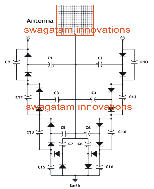
Parts List
All Diodes are 1N4148
C1---C8 = 0.22uF/100V mylar
C9----C16 = 33uF/25V electrolytic
Improving the Free Energy Device
The following more comprehensive free energy deriving circuit design was forwarded to me by one of interested readers of this blog Mr.Prashanth Dhonde.
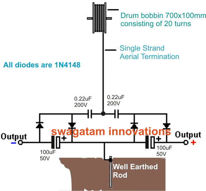
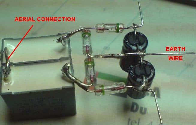
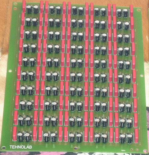
More info on the above design:
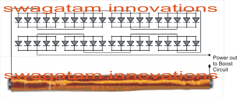
Using Fast Recovery Diodes
In order to generate more electricity, it is possible by stepping up with more diodes. To make it work properly, the type of diodes and the construction of antenna play a crucial role.
To begin with this process, let us first start setting up the antenna. In order to set an antenna properly, there are some key issues to consider.
An antenna should be made of Ferrite and a height of 30 inch rod is an ideal option to setup the antenna for receiving radio waves.
In regard to diodes, the Geranium the lowest loss diodes and a low breakdown junction voltage of ~ 0.2 - 0.4 Volts is ideal, in case you are unable to find the you may use the regular 1N4148, would just work.
A radio wave gets intercepted in areas with higher concentration and traffic congestion. In this kind of situation it is seen that each diode can pull around 30mV.




Questions & Answers
TODAY I READ THE ARTICLE. AFTER EXPERIMENT POSSIBLE HOPEFUL RESULTS I COMMENT. MY AREA OF STUDY IS ELECTRONICS AND MATERIAL SCIENCE FOR FORTY YEARS. AFTER RETIREMENT FROM COLLEGE SERVICES I DECIDED FOCUS ON SUCH EXPERIMENTS.
very good. I like this. hopefully we will see this as standard and escape from the fossil fuels and nuclear power plants.
Thank you very much for your useful feedback.
where’s your podcast? seriously, get on that. visuals. we like and NEED visuals. show us.
In the article: “In order to generate more electricity, it is possible by stepping up with more diodes.” An interesting article, but for anyone thinking they can get more power by using more diodes, that is wrong. The amount of power at the antenna is a value dictated by the antenna and the radio stations in the area. It is not related to how it is detected. By adding more diodes, what you are doing is increasing the output voltage using what are basically diode voltage doublers. However, every time you double the voltage, you halve the the output current current. So, it makes sense if you need a particular charging voltage but it will them tale longer to charge. Also, adding more diodes means there is an increased total voltage drop used up by the diodes so you won’t actually get exactly 2x voltage but slightly less and slightly less current as the diode effectively uses up the current. The more diodes, the greater the voltage, but the lower the current and the available output power.
yes .this is the true. As a hamradio operator I make this experiment long time ago ,and even vith a high power longwave broadcast station near me and my 80m longwire can’t detect hf frecvency that can lighting a 3.5 v/50ma bulb,also to measure an rf field from an 100w radiating antena I mus put my simple detector antena using a diode and a 30mA instrument no more than 2-3 mm distans.
Thanks for your valuable feedback, I agree with you.
with cincoG & beyond, is this gonna hijack our options? “space force”
Does it matter what region the antenna is in? or if you perhaps use a hillside instead of an antenna? Start near a creek or use a tree?
Yes, the longer and higher the antenna the better as well as a good earth. This isn’t generating energy form the earth, but from the various transmitters in your area. If you live on an area with lots of powerful transmitters then you will generate more power. If you live in an area where you can hardly pick up any radio stations, you are out of luck. Also, as this is an untuned antenna, you will find the power varying through the day and even the year, depending on local conditions, in the same way as some stations become stronger at certan times of the day.
What is the best antenna to receive 30 volts? I made different circuits, but it does not output more than 1.5 volts. Please guide me to make a better antenna. Thanks
A long wire as high up as possible is the way to go as well as a really good earth. Other aerial designs are more efficient but that is because they are designed to work at certain frequencies. If you have a local radio station that you know is powerful and at a particular frequency, you could tune in to that specifically using either a simple crystal set circuit or a specially designed antenna, Is it worth the effort or cost? You decide!
A specially designed antenna would just be the length that corresponds to the radio station tuning frequency, correct? (Using the c constant formula for speed of light.)
In need your help with your project
Hi Swagatam
i posted a question which was deleted, is there something wrong with the question, sorry if it the case
Bests regards
Gironimo
Hi Gironimo, which question are you referring to?
Hi Swagatam
The question December 15, 2021 at 10:51 pm(4 digital state ++ +- -+ — on) , i thought it was deleted as its unrelated to the original subject (free energy)
thks for your reply
It was not deleted, you can check it under the article, but yes posting comment under unrelated post may not be good for the site!
hi Swagatam
I have a question, what is the meaning of 4 digital state ++ +- -+ — on off do this do that …..in a circuit of leds(info from of an engineer ) i always do with 0 and 1 using and nor xor gates but with plus and minus i don’t understand if its the same thing
Thks in advance
Gironimo
Hello! Let me explain something to you. leave the circuit aside and take only the long wire antenna. This will capture electricity from electromagnetic waves of positive value and another wire that you will take from a grounding will give you negative electrical charges. Put a measuring device between them and you will see how many volts it gives you. For more volts, you will increase the length of the wire.
Hi Geronimo,
Sorry, I have no idea about it. Can’t figure it out!
Hi Swagatam
if it can help i built one yesterday
and i got up to 40 volts using just two MKP-X2 220N and 4 diode germanium 1n
the current is too weak about 0.026A at the out of a capacitor,
1.My question is how to increase current.without adding more Cap and Diode (i know that to increase current i can increase current)
2. which capacitor y advice me to wire with the circuit to charge quickly voltage
Thks in advance
Thank you Gironimo for updating the results, it looks very encouraging.
However, unfortunately, increasing the current may not be possible unless more number units are added in parallel.
Thank y Swagatam i forgot to notice that
Antenna i m using is coaxial used for Tv installed on the roof of the building at about 15 Meters
Sincerly
No problem Gironimo, thanks for updating the information!
Mi comentario seria una casa seria abastecida por este sistema de energia libre ,y no depender de las grandes monopolios de la energia caliente que nos venden
hello everyone where can i buy this kit. Can anyone make it for me?
What happens if the power grid fails
Instead of the drum bobbin, can we use lightning arrestor rod or old wireless receiver antenna. kindly let me know.
The drum bobbin is air cored according to me, so iron or ferrite cored bobbins will not work
Hello
I need a good free energy circuit to charge a LiFePO4 leisure battery in my RV. Can you help me?Thanks
Why not just power a joule ringer and use the coil to run a second transformer to run an op amp to up the voltage and drive an avalanche transistor as a current source at high voltage?
Hello,
wonderful ideas here! But the schematic under “Using Fast Recovery Diodes” shows the groups of 5 diodes are facing each other and not in series. Can you explain how that works? Also, how many turns of what size wire is over the 30″ ferrite rod?
Thank you in advance for your answer,
Sincerely,
Steve
Hi thanks, yes the diodes seem to be connected with cathode to cathode in series, which will simply not allow any current flow. I took the pics from one of the free energy forums, so have no idea regarding the working concept behind this configuration.
Sir,
Concerning the “How to Collect Free Energy from Atmosphere” I would like to built several pcb(Dragan Kljajic) but I have not the scaled printed circuit picture. I got one pcb drawing but not in proper size that would fit the components.
Could you please send me the PCB picture if you have it.
Thanking you in advance
I can help You !
zszabo@freemail.hu
Hi Hasan,
I am really sorry, making the PCB design can be difficult due to lack of time…I wish I could do it for you!
Hello Swagatam. Please May I have a circuit designed by you which I can integrate with readymade NE555 Module to properly drive IRF9540N which is a P-Channel Mosfet I plan to you to Drive an Inductor and do further test on?
My input voltage will be between 24V to 36V.
Please your help is Needed.
Hello Dare, please specify what exactly you are trying to implement, I will try to help!
Very low forward voltage drop diode is 1N5817 I think they are more efficient than diodes with germanium 1n34 !
Thank you for your fast reply. I have another question if I can , after the fourth (last)turn to the second row the wiring changes why? This is regarding the geranium diodes schematic.
Thanks Jim
There’s no change in the coil, it’s uniform from start to end.
In your geranium diode diagram is the antenna 30” (ferrite) long? How many turns should I use?Have you or any of your followers made this ,and what was there out put voltage?
Thanks Jim
It’s between 300 to 1000 turns of 30 SWG wire.
I haven’t tested it yet!
Hello swagatam, kindly look at d video in d link below and advice if it could work.
Regards
Hello Stanley, that’s a super FAKE video, will never work. The scene was paused and changed twice, that clearly shows the set up was manipulated.
About 1947 as a kid I met a fellow in Sydney who had built a simple full-wave, un-tuned crystal set which he used to drive a tiny motor he made out of a match box with wire coiled around it, thin wire brushes & small magnets. It depended largely on 6 local radio stations to drive this little motor flat-out.
That looks so amazing, Thank you for updating this interesting incident, appreciate it a lot!
The capacitors are not properly connected, need to change the polarity one full side.
GREEN GREETINGS SWAG: Antenna power = pretty useless. An old fellow tenting in a city caravan park had 3 solar garden lights with switches; these he daily put in the sun for night lights.
For 33 years we have had only one ordinary 12 volt car battery so power has cost us nix over decades & battery does everything except power my 25year old homemade Prize dual trike with 1/4 hp motor that attracts no rego, license or insurance on highways, but not freeways in this country. All home large appliances are 12 volt (none 240 or 110 V) & largely homemade like: fridge (average power = 2.8 watts with 15cm foam all round, blender = small starter motor, TV, vacuum cleaner, coffee boiler, fans, pumps (some items worked off small solar panel without battery), insect zapper, many tools, laundry, bed warmer, computer & printer, brilliant LED lights, 2-way radios, sewing etc. Then there are many small devices either solar or preferably windup like: FM/SW radio, torches, shaver, calculators, stirrer, saw, brush cutter etc. The stove is my small 1979 smokeless single-stick invention that has air preheating & afterburning. But when in Cornwall UK – warmest county & only 10 minutes snow when visiting for 7 years – the all-glass veranda facing south heated the entire home for free to beyond summer temp for hours after sunset! Incidentally, the current to charge latest home mentioned car battery is provided by only a 46 watt PV solar panel + it charges the trike battery!!! If y’all want to know more I’m Dr.Pat Howden.
What if, as predicted imminently by great panels of US experts, that no: jobs, banks, markets, utilities, health, car, fuel, energy (California is reportedly verging thus), water, partner, security or happiness…? Disaster Survival is highly correlated with home multi-tasked self-sufficiency level as many experts agree, & we have been – including emission-free & total solar + edible jungle + solar dual vehicle (trike) – for 1/3rd century! Not long ago our Centerlink (dole, employment, pension…) + Tax office + Army + Medicare were on strike – intending to be at length.
GREEN GREETINGS TO YOU TOO Dr. Pat, thanks for sharing your wonderful experience and knowledge with us, it is indeed very inspirational…please keep up the good work, and keep enjoying!
HELLO Swagatam thanks for ur tutorials .plz help me with the answers to these questions
1, Is mylar capacity polarized + & –
2.must the antenna be up to 150feet be it works
3. I used 0.22uf/100v electrolyte caps; is it accepable,although no single output
4. what type of wire should i use for the antenna
5. plz must i use earth materials for the earthing
I appreciate your response
Hello Okachi, sorry, I cannot suggest personally anything regarding this concept because this article was referred from other forums and websites….please do it as per your own understanding and evaluations.
I simulated the circuit described and make it available here tinyurl.com/y6wcb2b5 . It might look different, but electronically it is exactly the same. One can experiment with different load resistors. It is quite simple a negative and positive voltage multiplayer.
Additional Notes.
1. If you know the altitude of your antenna above ground, you can guesstimate the atmospheric potential at that altitude with the formula given so that you can determine safe and appropriate voltage ratings for your capacitors as well as be aware of handling while they are charged. Make sure to double that to consider days in which the atmosphere is more charged. Do not underestimate the importance of safety when handling capacitors, charged or not. The capacitors described don’t store much energy so they are generally safe but people are likely to modify the circuit potentially making it very dangerous to handle. It is well known there is an electrical potential between ground and the altitude above of an antenna or charge collector. On the other hand, what this circuit does is harnesses stray electromagnetic fields, and RF noise. Yes it is wireless transmission of energy, but it is not atmospheric energy.
Thanks Keith, that looks great, however how can the simulator estimate the amount of potential difference available in the atmosphere, because that’s the key element behind the success of this experiment.
Dear Sir.
Please i wish to build this circuit for my project as i live in a suburb with no electrical energy, now my question is, Can i use the circuit and connect it to a DC Car batterry so for it to charge then use an Inverter to step up the voltage so to macth my requirement? i will appreciate your help sir.
Thanks.
You are welcome, Deogratia…The circuit will need to be extremely huge to accumulate the amount of energy required for charging a battery, in a limited scale it would be quite ineffective
Thank you very much sir, so you mean there is no way to step up the voltage to any way that can charge a DC battery? i guess if the circuit can charge a batterry then it can push an inverter that can supply medium equipments, i am just asking if the idea can work out well via experiment… thanks for your time and i look forward to be hearing from you…
Dear Deogratia, the above circuit is only for experimental purpose, it cannot be used for running a house…it won't produce that much power…
Dear Swagatam Majumdar
I created this circuit but it generated 0.1 volt and need to time about 2 min for reaching to 2 volt and when i use this circuit by a very low amp LED this circuit discharge suddenly and again requires 2 min time for charging.
Please help me and explain what can i do about voltage that it generates 2 volt at first and does not need to time for charging.
Best Regards
Dear Ali, it will probably depend on the antenna size, try with a more bigger antenna and see if that improves the results…
thanks for updating the info
I made a fractal antenna and it's has a capability to capture more variety of waves giving more power
All the capacitors are reversed on the left side of the schematic. I built it and it didn't work until I corrected this.
Thank you for updating the info!
hello swagatam,
does this comes with a high power output?
hello mark, no it doesn't…
I took this circuit from another site so I am not entirely sure about its working and the results….wish you all the best!
hi Swagatam Majumdar,
i am very impress when i see your website by mistakly. I am software engineer but from chield hood i like rnd of rnd,tv,tapes and computer repairing but many time i am unsuccessful due to no knowledge of electronics or electrical education.
i want to learn circuits from ABCD what i do.
I am regular update with new software but circuit level i am zero. Can you given me suggestion for i learn or not. If not then no problem if yes then give me guidance.
sure, I'll try my best to teach you electronics, you can ask any specific question related to electronics and get it solved from me.
Hello sir
I have some problems – about the reception of mobile phone signal – and the weakness of surfing the Internet – via USB modem – making antenna alone but also indicate weak dwell signal area – and I found booster mobile signal – but it's expensive – Is there a small semi to meet this work and get on the circle a good signal
Hello soon time,
sorry I do not have much idea regarding this subject, it could be quite complex to find an easy solution for it.
Hello sir
Really work very well
But ask …!
Does it work on mobile networks Trdat – – 3G – 4G – because I live coverage area is too weak to connect to dial + Connectivity via USB modem
Hi Engr. Swagatam,
Can you make a topic about tesla's patent "Apparatus for utilizing radiant energy"…tnx
it seems, actually these concepts never worked satisfactorily according to me, otherwise we would have seen these being used in every home by now…
Hi Engr. Swagatam,
Can you make a topic about tesla's patent "Apparatus for utilizing radiant energy"…tnx
Hi eshkariel, I will surely research the subject and try to post a related article in this blog.
Amazing when connected correctly, low voltage yet great output
can you explain it in detail?
You can make 20 of this and use vortex connection to get high Wattage Output. By Vortex, I meant Directing each out put to separate caps each and then connecting the caps in series using a DIODE.
anyone trying to make this circuit will also have to be extra sure to get genuine germanium diodes which have low forward voltage and careful when soldering because they are very sensitive and easily damaged..
I tried making the simpler circuit above some years back after seeing it on you tube charging a handphone, it failed to work, not sure if its because of failed components or because it simply doesn't work
the output could be too trivial to notice….perhaps many such circuits needs to be connected in parallel to achieve anything that might be worth considering..
Sir 0.22uf capacitor is not available in my city can you suggest me equivalent. And if i connect a 20ma led with one circuit then does it glow or burn out.
My home is on 2nd floor then the antenna is necessary or not..i means that i will use a shorter anntena or iron rod
Hi Syed, I have not yet tried this practically so cannot say about the results, but an LED will not burn I think, because the setup may not be capable of generating that much power.
0.22uF is not acritical value, you can any other capacitor with nearby values.
antenna is a must and needs to be included no matter on which floor you are, without antenna the circuit may not produce the intended outputs
swagatam i am going to do this project.if i start did i get output .what type of material should be used for antenna
CJ, actually I have not yet tested this circuit, so I am not sure abut the results, however many have tested and have been successful in getting reasonable outputs….
Sir can you suggest me a circuit in which first we charge capacitors with 12v then these capacitors give accurate 12 or 11v just for 5 or 10sec
Thanks
Syed for this you may have to employ huge caapcitor may be upto 10000uF, it will also depend on the discharge rate (mamps) of your application.
dear sir pls tellme swg of wire its length r whitch type antena will be useable to make this circuit
dear prasanna, you can use any standard flexible wire for it which we normally use in our home wiring. …….1/18 could be tried
Hi sir !!
Could you please tell the output form, i mean dc or ac and if ac so in which waveform.
Thanks !
Hi sarib, the output will be DC since it would be from the capacitor's stored energy which is always DC
I have completed the circuit and it works great, but in the bottom picture there are 50 circuits. Any idea if they are connected in series or in parallel? I have tried series to increase the voltage and it keeps decreasing rather than increasing. Any idea how you can hook this circuit up in series?
That's great and interetsing, because most people have a skeptical view about such concepts,
in the bottom image the configurations are in parallel in order to increase current gain and the overall power of the output….it could be done in parallel first and then those parallel strings could be further put in series for getting a sustained boosted voltage
Is this inspired by Tesla's Generator?
yes that's right
thank you Mr. Swagatam
I appreciate your kindness.
Dear
Swagatam, please i want a circuit that will changeover between two
batteries for an inverter while the strong battery is powering the
inverter, the weak one is bieng charged automatical by a charger
connected to the inverter…. Please I want to know if it is possible
thank you in advance.
Hi Emmanuel, the last circuit link above will changeover from one battery to the other, so any other circuit won't be required.
Mr.
Swagatam, and also do I have to combine the two circuit diagrams which
is the dual battery changerover and the split charger? Thank you.
Thank
you Mr. Swagatam… I wl post you the images when and am done and I wl
also let you know when I face any difficulties…thank you once again.
Dear Emmanuel,
A split charger would be preferable, you can build the following design, it is supposed to charge the batteries in a split manner by selecting the battery according to their charge levels:
https://www.homemade-circuits.com/2014/05/twin-or-split-battery-charger-circuit.html
Dear
Swagatam
another little confusion is the kind of charger circuit I will need in
charging the dual configuration setup of the batteries, because each of
the batteries am going to use have a high "AH" 12v 100AH and 12v 120AH.
Meaning do I use a single charger or a split charger type.thanks you
once more.
thank
you for your quick respond, but the inverter am having is a homemade
555 squarewave inverter I made following some of your post and it does
not have low battery indicator, so if you could please help me with a
simple circuit on that so that I can continue from the previous solution
circuit you gave.thank you once again.
Dear Emmanual,
If you have a low battery indicator in your existing inverter then you could probably try the following design:
https://www.homemade-circuits.com/2012/11/automatic-dual-battery-changeover-relay.html
Thank you Eng. Swagatam I appreciate what your help may God richly bless you.
please Eng. Swagatam can you also sadjust a simple inverter circuit diagram the can power electronics and inductive load. thank you
sorry for bordering you.
you can try any 4047 based inverter design, and add a 0.22uF/400V capacitor at the output of the inverter….. this will fulfill your requirement reasonably.
thank you Eng, Swagatam, but the reason why i need this solution is because the battery turns to burn the components and the jumpers on the circuit board.
Here is the link to the circuit i built.. https://drive.google.com/file/d/0B15SzCeSV14XekxNMEV6dl9YY2c/edit?usp=sharing
the image is not opening,
anyway, check the condition without any load…. if still it starts burning would indicate a malfunction in the unit.
unless the voltage is increased AH will not cause any harm to the inverter.
Eng. Swagatam please I need a simple circuit that can reduce 12v/60Ah to 12v/20……25AH for my homemade inverter. thank you.
mawuli, if your inverter is rated to work with a 12V supply you can comfortably use the 12V/60AH or any higher AH battery without worrying…unless the voltage is increased AH will not cause any harm to the inverter.
thanks,
but please try to get that within a month. It would be a great pleasure. I have to present it soon.
again thanks,
with regards.
I'll try my best. Thanks
hi,
I am looking for an advanced electronic based project on changing weather and climate. It could be and new type measuring device or analysing device using electronics. Measuring weather attributes like temperature, daily sun shine hours, humidity, wind,
precipitation, etc will do. please please tell me if you have any one, even from outside your website. Iam a 9th grader, and i want to take my project to the national level.please give me the link of the project you know or tell me yourself about any project. It would be an great pleasure.
presently I do not have an appropriate info regarding the subject, if I happen to come across one I'll surely let you know about it.
hi,
I have microcontroller, currently i have atmega 16 and I program with a software called bascom AVR and then compile it and then feed the program with ponyprog 2000 software, using serial port. Please send me the project with microcontroller.
Hi, this could be a complicated design and would need microcontrollers, presently I do not have an appropriate info regarding the subject, if I happen to come across one I'll surely let you know about it.
Thanks!
what about out put voltage??? and anyone make this circuit????is this working…Pls tell
One of the best circuits ever seen. If I use any voltage booster IC(output adjustable one) from National Semiconductor or Texas Instruments and configure it for lets say 6V then if the voltage at the input increases or decreases will I get 6V at the output? If the output changes will the current change or voltage will change. Can I use 1N4007 diodes instead of 4148, 1N4007 is used for rectiication but whats the main difference between the two.
Thanks! I don't think ICs will work here.
1N4007 cannot be used since they are not specified for high speed detection. 1N4148 react much faster compared to 1N4007.
Do you think 150 feet antenna is practical??
Hi sir,
I found this link:
frenergy.ca/tapping-into-200-volts-positive-of-free-unlimited-and-unmetered-pure-electrical-energy.html
On this design, frenergy.ca/wp-content/uploads/2013/05/pyramid-flux-capacitor.bmp
what should be the proper capacitor/diodes to use? or any suggestions for this.
Thank you.
Hi Raymund,
The blue cap is 0.0002uF/5000V
The electrolytic cap looks like a 22uF/100V
The diodes could be 1N4148 or BAT30
hi sir!!!
1. On the last picture, can you give me the schematic diagram?
thanks in advance!!!!
From areal power what about thunder lighting? Could make any dangerous ?
it's the same as the second diagram, just add many of them in parallel.
Hi dear sir,
Can you please provide us high power led driver's all wattage circuit digram
my email. id is swapnilsinalkar@rediffmail.com
There is no all wattage circuit. Each category of LED need own driver. If you are interested I can do it for you if you tell me your led type and configuration.
zszabo@freemail.hu
Zoltan
Hi Shiv,
You can try the following design:
https://www.homemade-circuits.com/2013/06/universal-high-watt-led-current-limiter.html
Use LM196 for the IC if the requirement is upto 10amps.