The circuit and the mechanism I have explained in this article may be considered as the easiest and perfect dual axis solar tracker system.
How the Dual Axis Solar Tracker Concept Works
The device is able to track the daytime motion of the sun precisely and shift in the vertical axis accordingly.
The device also effectively tracks the seasonal displacement of the sun and moves the entire mechanism in the horizontal plane or in a lateral motion such that the orientation of the solar panel is always kept in a straight axis to the sun, so that it complements the vertical actions of the tracker appropriately.
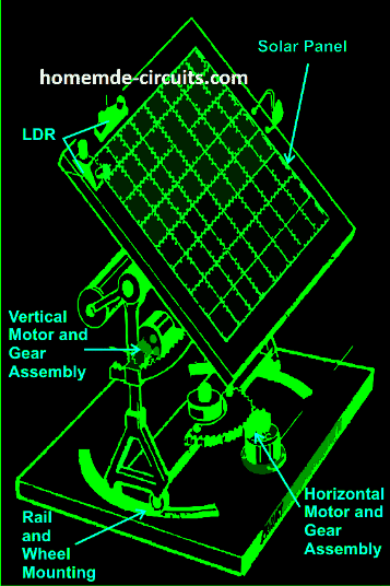
As shown in the figure, a relatively easy mechanism can be witnessed here. The solar tracker is basically mounted over a couple of stand with a central movable axis.
The pivotal arrangement allows the panel mounts to move on a circular axis over almost 360 degrees.
A motor gear mechanism as shown in the diagram is fitted just at the corner of the pivotal axis in such a way that when the motor rotates the entire solar panel shifts proportionately about its central pivot, either anticlockwise or clockwise, depending upon the motion of the motor which in turn depends on the position of the sun.
How the LDR Circuit Works
The position of the LDRs are critical here and the set of LDR which corresponds to this vertical plane movement is so positioned that it senses the sun light accurately and tries to keep the panel perpendicular to the sun rays by moving the motor in the appropriate direction through a definite number of stepped rotations.
The LDR sensing is actually accurately received and interpreted by an electronic circuit which commands the motor for the above explained actions.
Another mechanism which is quite similar to the above vertical setting, but moves the panel through a lateral motion or rather it moves the whole solar panel mount in circular motion over the horizontal plane.
This motion takes place in response to the position of the sun during the seasonal changes, therefore in contrast to the vertical movements; this operation is very gradual and cannot be experienced on a daily basis.
Again the above motion is in response to the command given to the motor by the electronic circuit which operates in response to the sensing done by the LDRs.
For the above procedure a different set of LDRs are used and are mounted horizontally over the panel, at a specific position as shown in the diagram.
How the Solar Tracker OpAmp Control Circuit Functions
A careful investigation of the circuit shown in the diagram reveals that the whole configuration is actually very simple and straightforward.
Here a single IC 324 is utilized and only two of its op amps are employed for the required operations.
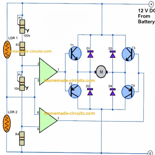
The op amps are primarily wired to form a kind of window comparator, responsible for activating their outputs whenever their inputs waver or drift out of the predetermined window, set by the relevant pots.
Two LDRs are connected to the inputs of the op amps for sensing the light levels. As long as as the lights over the two LDRs are uniform, the outputs of the op amp remain deactivated.
However the moment one of the LDRs senses a different magnitude of light over it (which may happen due to the changing position of the sun) the balance over the input of the opamp shift toward one direction, immediately making the relevant opamps output go high.
This high output instantly activates the full bridge transistor network, which in turn rotates the connected motor in a set direction, such that the panel rotates and adjusts its alignment with the sun rays until uniform amount of light is restored over the relevant set of LDRs.
Once the light level over the relevant LDR sets is restored, the opamps again become dormant and switch off their outputs and also the motor.
The above sequence keeps on happening for the whole day, in steps, as the sun alters its position and the above mechanism keeps shifting in accordance to the suns position.
It should be noted that two sets of the above explained circuit assemblies will be required for controlling the dual actions or simply to make the above discussed dual tracker solar system mechanism.
Parts List
- R3 = 15K,
- R4 = 39K,
- P1 = 100K,
- P2 = 22K,
- LDR = Normal type with a resistance of around 10 K to 40K in daylight under shade and infinite resistance in complete darkness.
- Op-amps are from IC 324 or separately two 741 ICs may also be incorporated.
- T1, T3 = TIP31C,
- T2,T4 = TIP32C,
- All diodes are 1N4007
- Motor = As per the load and size of the solar panel
How to Add a Set/Reset Facility in the Above Circuit
At the first glance it might appear that the above circuit does not incorporate an automatic resetting feature.
However a closer investigation will show that actually this circuit will reset automatically when dawn sets in or in the morning daylight.
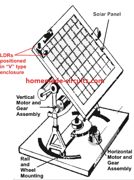
This might be true due to the fact that the LDRs are positioned inside enclosures which are specfiially designed in a "V" shape for facilitating this action.
From the reflection of of the rising sun light, during morning hours the sky gets more illuminated than the ground.
Since the LDRs are positioned in "V" manner, the LDR which faces more toward the sky receives more light than the LDR which faces toward the ground.
This situation activates the motor in the opposite direction, such that it forces the panel to revert in the early morning hours.
As the panel reverts towards the east, the relevant LDR begins getting exposed to even more ambient light from the rising sunlight, this pushes the panel even harder toward the east until both LDR are almost proportionately exposed toward the east rising sunlight, this completely resets the panel so that the process begins all over again.
Set Reset Function
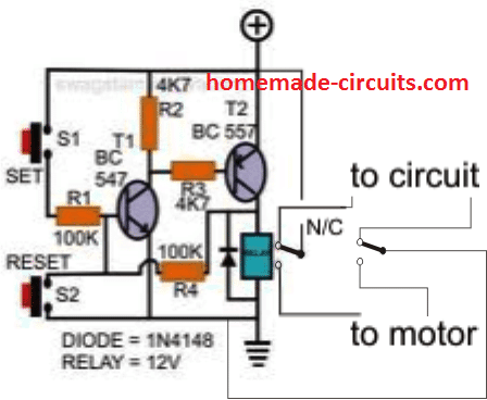
In case a set reset feature becomes imperative, the following design may be incorporated.
The set switch is placed at the "sun-set" end of the tracker, such that it gets depressed when the panel finishes it's days tracking.
As can be seen in the below given figure, the supply to the tracker circuit is been given from the N/C points of the DPDT relay, it means when the 'SET" switch is pushed, the relay activates and disconnects the supply to the circuit so that the entire circuit shown in the above article now gets disconnected and does not interfere.
At the same time, the motor receives the reversing voltage via the N/O contacts so that it can initiate the reversing process of the panel to its original position.
Once the panel finishes its reversing process toward the "sun-rise" end, it pushes the reset switch placed suitably somewhere at that end, this action deactivates the relay again resetting the entire system for the next cycle.



Questions & Answers
Solar energy is an efficient green energy which we should dig more t o be educated also we should no more aboult feuless generator
You are correct, appreciate your feedback.
Hello,
I am a beginner at electronics and I am trying to understand this circuit. Could you please help me understand the purpose of the diodes? Won’t the circuit work the same if they were just excluded altogether.
Thanks!
Hello, the diodes are for protecting the transistors from the motor’s reverse spikes or back EMFs. The diodes short circuit the spikes preventing them from entering the transistors from emitter to collector
Thank you! That makes sense
Hi Swagatam. I’m a new commer actually I’m learning electronics, please tell me the operating current for both circuits. I can run on 12volts DC current. Thanks
Hi Asim, the current will depend on the motor current specification, and on the solar panel weight
Hi Swagatam,
Do you think heat sinks are necessary for the transistors in this circuit? I only ask because I noticed that they get very hot even after only a minute or so of operation. If so, would simply bolting a piece of aluminium to each measuring approx. 20mm x 20mm x 1.8 thick be sufficient or would a finned heat sink be required?
Also is it okay to connect two transistors onto one larger heat sink of say 40mm x 20mm?
Thanks again for your help.
Regards,
Jim
Hi Jim, putting maximum heatsink is always a good idea since it guarantees optimal performance from the devices under all circumstances.
However, since here the motor is operated only intermittently, large hetasinks may not be required, and you can safely go ahead with small pieces of aluminum.
That’s great! Thanks for such a prompt response Swagatam.
Regards, Jim
You are welcome!
Hi again Swagatam,
Please ignore my earlier question tonight regarding adding limit switches to the circuit. It’s been some time since I read the details of the circuit as I have been busy with other matters and I had forgotten about the automatic reset feature of the design.
Regards,
Jim
No problem Jim, let me know if you any further problems or questions, I’ll be happy to help,…and glad the circuit worked for you!
Hi Swagatam,
Thank you for providing excellent and easy to follow instructions for a single axis solar tracker! I have made the circuit as described in your article and it works well. I am now in the process of building the physical device, but it has occurred to me that I will need to install limit switches.
My question is :
Could limit switches be wired into your circuit?
One challenge with setting up limit switches on my device is that the motor is a bit too fast (36rpm) so even after the power is cut the 600mm diameter table continues to turn for a few inches past the motor which is mounted at the periphery of the table.
Thanks again for all your generous help!
Regards,
Jim
DEAR SIR,
THE LDR ARE NOT WORK IN DIRECT SUN LIGHT, PLEASE HELP IN THIS QUERY.
Thanks Swagatam!!!
Kashmir, the LDRs must be housed inside tubular enclosure and positioned at a “V” shaped angle, as shown in the 3rd diagram…this ensures that sunlight does not reach the LdRs directly….
buenos dias,
Hi Sir Swagatam, i want to make it a dual axis with the circuits above including the set/reset function,
my question is instead of duplicating the whole circuit above, can i use a single LM324 using all the 4 op amps of the IC,
2 for the vertical axis and the other 2 for the horizontal axis?
If yes, is there any changes on the orientation or any addt’l component to be added on the tracker circuit and set/reset function? by the way im using tip35c and tip36c. what should be the amp/hour of the supply voltage?
im going to duplicate each and every components in the two circuits above except for the LM324
i already have 2 12v geared motor for the horizontal and vertical axis.
Hello Amor,
the above circuit is built with 4 opamps from the LM324, therefore you will also have to use the same IC for making the design. The amp hour of the battery will depend on the solar panel rating, ideally the solar panel must have 75% less current value than the Ah value of the battery, if the battery is 100 Ah, you can have a panel rated at 25 amps, this will handle the charging as well the motor load
Good remark from you which prove that you'r in the field , that's why I prefer using micro controller in such circuits.
Hi Swagatam,
Do you think it would be possible to add some hysteresis to the circuit to save on energy? Would it even be possible to use 555 timer to do this?
All the best,
Brian
Hi Brian, adding hysteresis could stop the panel from adjusting to the best optimized positions, which in turn could cause inefficient charging or inefficient solar consumption…so both ways it would be the same…
I have not yet investigated the IC 555 option, it might be possible.
@Swagatam, In the SET / RESET circuit you have shown, the power to the tracking circuit is disconnected when the SET switch is activated. How can the LDR's work at that point of time with no power applied to the circuit ? Please elaborate.
M&D, the LDR circuit is deactivated when the "set" button is pressed by the panel, but as soon as the panel restores itself back in the original position the "reset" button is yet again "pressed" by the panel which reverts the relay contacts back to the "circuit" position enabling the circuit with the supply voltage
Hi friend
I made this circuit, it is working beautifully and the set/reset switch also working great but only problem is when the sunset limit switch activated it goes reverse and stop but again searching light intensity rotating up and down continually so I have to stop the circuit supply manually. In the night ? time no light condition but this motor works only one direction and stuck then the transistors start to get hot and some times blown up. So my dear friend please help me to overcome this problem.
At night time condition is both LDRs resistance is very high and no center voltage, both presets are not respond motor goes only one direction.
Thanks Ranjith, you can rectify the problem by adding an additional relay driver stage whose relay stays activated as long as the sun light is just sufficient for the tracker to operate….as soon as the sunsets or the light become too low, the relay of this driver stage switches OFF, and in cuts off the battery supply to the motor
Greetings!
I built your circuit and works fine. However, I get "unbalanced" results sometimes. Can you tell me how to adjust "P1" and "P2" trimpots properly?
Thanks in advance and Mabuhay from the Philippines!
Thank you Swagatam.
Best regards
thanks wasmir, adjust the presets such that when lights are equal in intensity on the LDRs the opamp outputs are identical and become opposite only when there's a slightest difference in the light level on the LDRs
Greetings!
I built your circuit and looks good so far. However, I'm getting "unbalanced" response. How do you adjust the two potentiometers, P1 and P2?
Dear Prashant, I think you are trying to say that the circuit trips automatically to external electrical disturbances….
You can solve this by adding a 1uF/25V capacitors across the S2 terminals
Dear sir i use set reset circuit its work properly but in line if earthing circuit automaticaly on.
plz solve the problem how can i desable earthin for transistor.
PCB
hey @Swagatam could you please give me an estimate of total cost of this sytsem in INR as i am making a solar inverter for my final year project and wish to incorporate this with my solar panel…
Hi Soumitra, I have no idea about it since the design is mostly mechanical and the solar panel cost can vary a lot according to its specs…
also note that this project can be extremely tough for a novice so think twice before you decide on going ahead with it
Do you have a photo of the finished circuit on a breadboard? I'm having trouble getting the circuit to work and I think my problem is in the wiring of the H bridge.
Thanks
the opamps detect the sun light balance on the two LDRs and accordingly command the H bridge to switch the motors and restore the panel position until the light balance on the LDRs become equal.
it's impossible to use use LDRs directly with the Hbridge for getting the same results…not sure how you did it.
What purpose do the op amps serve? I was able to get a functioning circuit by connecting the LDR's to the H bridge directly.
Thank you
sorry, I do not have the picture of the finished prototype, the idea was taken from an old elektor electronics magazine.
you can isolate the H bridge section and check it separately using manually triggered signals across the transistor bases in order to simulate and troubleshoot the fault….
Dear Swagatam:
Many thanks for the circuit.
I built the circuit and have noticed the following.
(a) A possibility exists that both outputs are switched ON. How can we avoid this?
(b) When powering down, the motor rotates in one direction for a small amount of time and then stops. What could be the reason ?
Please comment.
Dear M&D,
both outputs ON is very unlikely, you might be witnessing a leakage voltage issue across both the opamp outputs during the transitions, even that's not possible because the switching thresholds of the two opamps are assumed to be set wide apart.
Connect a 3V zener and a LED in series with the output terminals of the opamps… this would possible solve all the encountered issues.
The LEDs would also provide the relevant indications.
I give you the credit for having tonnes of patience.
thanks very much!!
My set reset circuit is working. I checked by connecting red and green leds at N/C and N/O positions its working perfectly but when I connected a 12v motor it is not working.
When set is touched motor rotates one direction when reset is pressed the motor should rotate in opposite direction even reset switch is released but this is not happening when I released the reset switch direction is same as initial. It should rotate in reverse till again set is pressed actually.
Should I have to change the transistors with high current ratings
……..remember the tracker circuit receives power from the N/C contacts of the set/reset circuit shown in the last diagram above.
In the last circuit given in the above article, the motor will rotate only when the set button is pressed…the relay is not wired to rotate the motor in the opposite direction because we need only to set the panel back to its original position in one direction only, so the motor does not need to rotate on both directions.
When the set button is pressed and while the motor is rotating, the relay N/C contacts makes sure that the tracker circuit is switched OFF from receiving voltage and thus does not react in any manner while the above is taking place.
how to do…. anybody
can explain about it
hi, i have try this its working but a bit problem it runs only tape recorder motor, i want to run gare motor but i think there is a problem of current i have use bc 547,557 instead of tips what to do now?? regards
Ok I got the output.
working perfectly.
My next step is to implement simple mppt circuit to the solar panel output
Yes I did the same but not working
it means there's something wrong with the transistor connections, because as can be seen the circuit is very simple and should start working immediately.
Worked a lot on set/reset circuit but not working. I checked the base current of t1 when set is on and even off there is no difference showing 0mA. What to do ?
Are the resistors values to be changed?
the SET switch must be connected with the positive supply, and the reset switch must be in a switched OFF condition only then the circuit will operate..
how the relay and transistors are working
when set is pressed, T1 gets latched with R4
when reset is pressed the latch is broken.
Can you briefly explain the working of set/reset circuit
I am not getting the connection to 12v 8 pin relay. In the circuit 'to the circuit' means where to connect. I am usig KT 450 relay it has pins 1 4 6 8 9 11 13 16. Pins 1 16 coil 4 14 com 6 11 N/O 8 9 N/C. Guide me how these tins are connected in 2nd circuit please
………in the diagram the upper relay contacts (small white circles) are the N/C while the lower ones are the N/O
it means to the circuit supply rails (+) and (-)
you will have to find it by yourself with the help of a meter. find the common pole, the N/C and N/O contacts by trial and error or by referring to some relevant online relay diagram.
N/C will show continuity with the pole when power is not applied to coil, and N/O will connect when the coil is powered up.
please explain the design of circuit.Why should we take resistor values to compare with reference voltage.
For what purpose p1 and p2 adjusted.
you will have to learn how an opamp functions as a comparator for understanding the above circuit.
Briefly when the (+) inputs are high with respect to the (-) input the output of that particular opamp will be high and vice versa.
LDR in light will increase the voltage level across the relevant pin of the relevant opamp and when in dark will do the opposite with respect to the other pinouts reference voltages.
Thanks,
I meant to ask about the design and working of the circuit.
In case of op-amp 1, pin 2 is connected to 12v with the voltage divider setup consisting of resistors 13K,100K & 22K,by voltage divider method voltage at pin 2 is
= 12*(115/115+22)=10v is reference voltage. and op-amp 2 with reference voltage 4.3v
when LDR is in dark setting resistance is 12K.
When light falls on LDR which op-amp gets activated and how?
you will have to learn how an opamp is used as a comparator first to understand this fully, you can check out this article:
https://www.homemade-circuits.com/2012/03/how-to-use-ic-741-as-comparator.html
Can you tell me how the 5 pins of 12v relay is connected in second circuit
there are 8 pins, it will depend on the selected relay pin config.
Which type of relay is used in second circuit
DPDT
In the 2nd circuit R2 and R3 are given as 4k7 is it right or is it 47k
4k7 = 4.7k
Is ther any other easy circuit for set reset operation
pls read the section" How to Add a Set/Reset Facility in the Above Circuit"
Do you have any light sensor circuit for set reset operation because at sunset illumination is absent and morning sunlight will be present so if we use sensor for set reset can there be any circuit be designed
For set reset operation is there any sensor circuit which can be operated automatically
Why the need of variable resistors p1 and p2
p1 for crude adjustment
p2 for fine tuning.
there are two motors to be used one for east-west and other for north-south,the same circuit is used for two motors.i am not getting clarity about the above circuit is used for one motor functioning or both plz explain me
one circuit for one motor system, that means two of these circuits will be needed for the proposed dual axis operation.
actually i also assemble one circuit like this but part are different i use BD 239 BD 240 & BD 139 BD 140 at T1 T2 parts & IC LM 324. It is also same but when it start to track i adjust pot resistor but here some difference as one ldr get more light then motor moves slowly. ldr not giving balance resistance at same amount of light. I tried both small & medium LDR but both not working giving better result as excepetd so can circuit work better than my circuit. because im not electronic engg for reading the circuit. Caqn you give me suggetions & guidance. please reply.
you will have to set the presets by exposing the LDRs to same amount of artificial light.
the above setting should be tried until the motor completely shuts off or shows no response. Once this is set and confirmed, you can use it for the actual sun tracking implementation.
I understood the concept of tracker circuit,
can you explain the concept of set/reset circuit?
does the 12v supply to tracker circuit is related to rating of the motor?
it's already explained at the bottom section of the article.
the motor rating should be sufficiently large to handle the load of the panel while moving it
Sir,
we could like to implement this project.
can we be sure that this set/reset facilty work
you will have to confirm it by practical testing after understanding the concept.
PLS CAN I USE THE SET/RESET CKT TO CONTROL AN AUTOMATED GATE MOTOR(S), SO THAT WHEN THE MOTOR ROTATES TO OPEN THE GATE IT TRIGGERS OFF, AND THE OPPOSITE DIRECTION (WHEN THE GATE IS CLOSED) THE CKT TRIGGER OFF AUTOMATICALLY, AND HOW IS CONFIGURED……….. PLS SIR SWAGATAM, I WOULD LIKE TO ADD THAT TO MY FINAL YEAR PROJECT WORK, OR IF THERE IS A CKT THAT OPERATES THAT WAY…..THANKS, WAITING FOR YOUR RESPOND.
Christopher, please explain your requirement in a more elaborate and clear way, so that i can get the whole procedure accurately.
I have idea about reversing the panels. if we connect the relay supply form panels wires. in day time the relay will on and supply current to circuit and during night when panels stop supplying current the relay will Off and supply current to the motor so the panels will reverse..
Thanks! Yes, it's a good idea, worth trying.
shape memory alloy in series with pv control panels to create motion