In this article we are going to see, what force sensing resistor is, their construction, specification and finally how to interface it with Arduino microcontroller. We will also study a couple of comparator circuits based on 741 and LM311 ICs, for operating a relay using force sensitive resistor.
What is Force Sensing Resistor
A force sensing resistor senses the force applied to it and correspondingly changes its resistance. The resistance is inversely proportional to force. This means when the applied force high, it reduces its resistance and vice-versa.
The “force sensing resistor” or FSR is not an ideal term, since it is actually sensing the pressure and the output is dependent on the pressure on the surface of the resistor. The more appropriate name would be pressure-sensitive resistor. But force-sensing resistor became common term to refer it.
It has a wide range of resistance, it can vary from few ohm to >1M ohm. An unloaded FSR would have around 1M ohm and fully loaded would have around few ohm resistance.
The force-sensing resistor comes in various shapes; the common shapes are circle and square. It can sense weight ranging from 100g to 10Kg. The major disadvantage is that, it is not very accurate and has very high tolerance value. The accuracy reduces overtime due to usage. But it is reliable enough to be used for hobby projects and non critical industrial measurements. It is not suitable for high current applications.
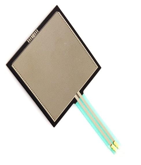
Specifications:
The device measures from 20 x 24 inches to as small as 0.2 x 0.2 inches. The thickness ranging from 0.20 mm to 1.25mm depending on the material used.
The force sensitivity is from 100g to 10Kg. The pressure sensitivity ranging from 1.5psi to 150 psi or 0.1Kg/Cm square to 10Kg/Cm square.
The response time of FSR ranges from 1-2 milliseconds. The operating temperature is from -30 degree Celsius to +70 degree Celsius.
The maximum current is 1 mA/Cm square. So handle this resistor carefully, do not apply huge current through this resistor.
The life time of FSR is greater than 10 million actuations.
The brake force or minimum force to respond by FSR must be from 20-100 gram. The resistance is not affected by noise or vibration.
Working of FSR:
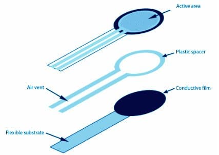
The force sensing resistor consists of three layers: an active area, plastic spacer and conductive film.
The active area where the force is applied, the plastic spacer which isolates the two layers and an air vent is provided for discharge of air bubbles. The accumulation of air bubble leads to unreliable results.
The conducting film consists of both electric and dielectric particles which are suspended in matrix form.
When force is applied it changes its resistance in predictable manner. These are microscopic particles ranges few micrometers. The conductive film is basically a kind of an ink coated on plastic film. When pressure is applied the conducting particles come close together and reduce resistance and vice-versa.
Basic circuits using force sensitive resistor:
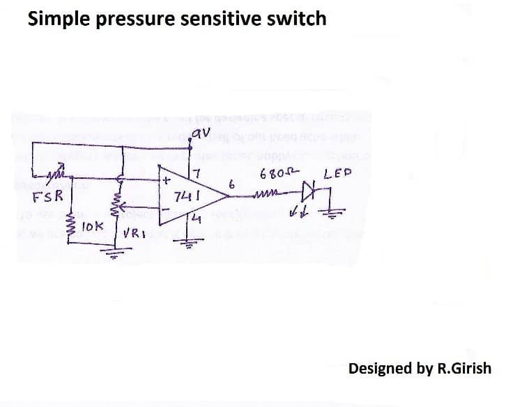
You can use this resistor for any application to detect changes in force. For instant, you can make a pressure sensitive switch by paring FSR with op-amp.
Interfacing with Ardiono
You can set threshold by adjusting 10k potentiometer. When you apply force to the resistor and reaches above threshold voltage the output goes high and vice-versa. Thus we can obtain digital outputs from it; this output can be interfaced to digital circuits.
Here is another circuit using arduino which measures different pressure level:
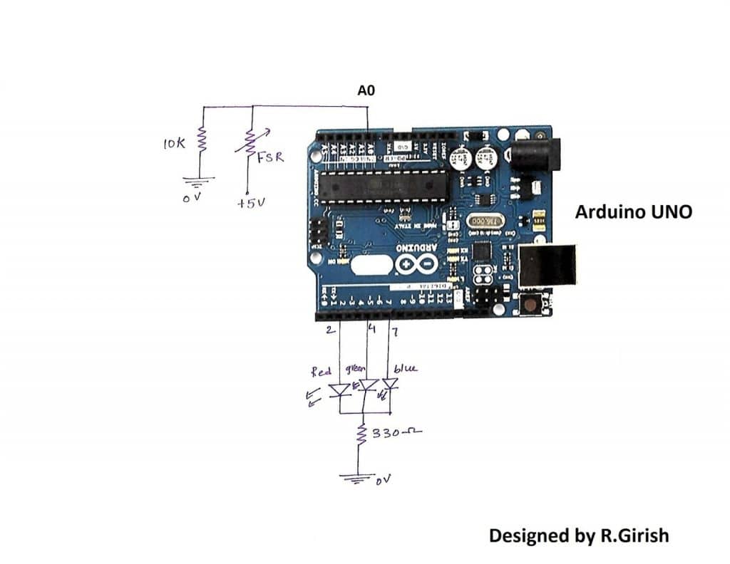
The input is fed to analog read pin, which takes different voltage levels digitally from 0 to 255.
User can set their own threshold level in the program.
When light pressure is given blue LED turns ON, when medium pressure is given green LED turns ON, if high pressure is applied red LED turns ON.
Just use your imagination to find new applications and it’s endless.
Program Code
const int LED1 = 2; // define LED1 pin
const int LED2 = 4; // define LED2 pin
const int LED3 = 7; // define LED3 pin
const int FSR = A0; // define FSR analog input pin

int fsrValue = 0; // variable to store the FSR value
int ledValue = 0; // variable to store the LED value

void setup() {
  pinMode(LED1, OUTPUT); // set LED1 pin as output
  pinMode(LED2, OUTPUT); // set LED2 pin as output
  pinMode(LED3, OUTPUT); // set LED3 pin as output
}

void loop() {
  fsrValue = analogRead(FSR); // read the FSR value
  ledValue = map(fsrValue, 0, 1023, 0, 255); // map the FSR value to LED brightness (0-255)

  if (ledValue > 170) { // if the LED value is greater than 170, turn on all LEDs
    digitalWrite(LED1, HIGH);
    digitalWrite(LED2, HIGH);
    digitalWrite(LED3, HIGH);
  } else if (ledValue > 85) { // if the LED value is between 85 and 170, turn on LED1 and LED2
    digitalWrite(LED1, HIGH);
    digitalWrite(LED2, HIGH);
    digitalWrite(LED3, LOW);
  } else { // if the LED value is less than 85, turn on only LED1
    digitalWrite(LED1, HIGH);
    digitalWrite(LED2, LOW);
    digitalWrite(LED3, LOW);
  }
}
This above code scans the pressure applied on the force sensitive resistor attached to the A0 analogue input pin, translates it to LED brightness, and then activates the LEDs depending on the translated value.
If the translated value is larger than 170, all three LEDs will light up; between 85 and 170, only LED1 and LED2 will light up; if it is lower than 85, only LED1 will light up.
In the configuration functioning, the LEDs are hooked up to digital pins 2, 4, and 7 and configured as outputs.
Using LM311 Comparator IC
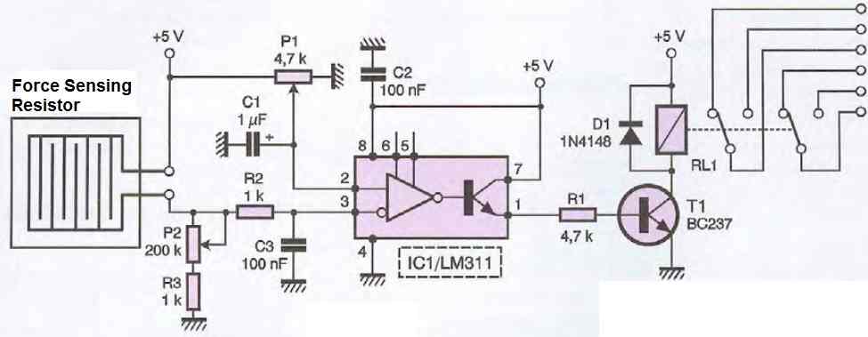
The force-sensing resistor (FSR) is connected between the positive supply and pin 3 of the LM311 IC. The resistance of the FSR changes with applied force, thus changing the voltage at pin 3 of the IC.
A 200K preset is connected between pin 3 of the IC and ground. This resistor acts as a reference voltage for the LM311 IC.
Another 4.7K preset is connected between pin 2 and the positive supply. This resistor sets the threshold voltage at which the comparator switches state.
The LM311 IC compares the voltage at pin 3 (which is the voltage across the FSR) with the voltage at pin 2 (which is set by the 4.7K preset). If the voltage at pin 3 is higher than the voltage at pin 2, the output of the IC (pin 1) goes high, otherwise, it goes low.
The output of the LM311 IC (pin 1) is connected to a transistor relay driver. This driver amplifies the signal from the LM311 IC and drives a transistor that switches the relay ON/OFF.
So, when a force is applied to the FSR, the resistance of the FSR changes, which in turn changes the voltage at pin 3 of the LM311 IC. If this voltage is higher than the threshold voltage set by the 4.7K preset, the output of the LM311 IC goes high, and the transistor relay driver switches the relay ON. If the voltage at pin 3 is lower than the threshold voltage, the output of the LM311 IC goes low, and the transistor relay driver switches the relay OFF.
In summary, the circuit senses the force applied to the FSR and uses the LM311 IC to compare the force with a preset threshold. If the force exceeds the threshold, the circuit switches ON the relay.


Questions & Answers
I have an issue in my code for FSR with arduino.
below is my stackoverflow question link.
https://stackoverflow.com/q/76833422/20893331
Thanks in advance.
Sorry, my Arduino coding is not good, so I am unable to solve your query
Hi: Would your circuit for the “simple pressure sensitive switch” work to activate a micro vibrating motor between low and high force (resistance) thresholds? Thanks.
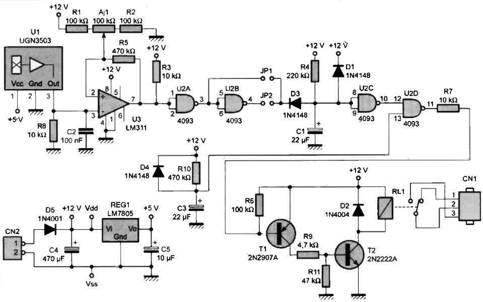
The last circuit should work. Just replace the relay RL1 with your motor.
Thanks much!