• Skip to main content
  • Skip to primary sidebar

Homemade Circuit Projects

Need circuit help? Post them in the comments! I've answered over 50,000!

Blog | Categories | About | Hire Me | Contact | Calculators-online
You are here: Home / Audio and Amplifier Projects / Extended Telephone Ring Amplifier/Repeater Circuit

Extended Telephone Ring Amplifier/Repeater Circuit

Last Updated on May 15, 2026 by Swagatam 2 Comments

Table of Contents
  • Circuit Operation
    • Circuit Diagram
      • List of components for the proposed Telephone repeater circuit

The discussed phone repeater circuit can extend the range of your land line ring sound from the phone such that one is able to make a call heard in another room or even in another house.

By: R.K. Singh

Circuit Operation

The circuit can be connected with an attached buzzer, the buzzer with a driving circuit is then further used to expand the range of it. Even a warning light (a light bulb / bulb for example) when be connected in case a person with hearing impairment was to use the device. To achieve multiple units one may connect more than relay output contacts for the respective loads.

How the phone repeater works:

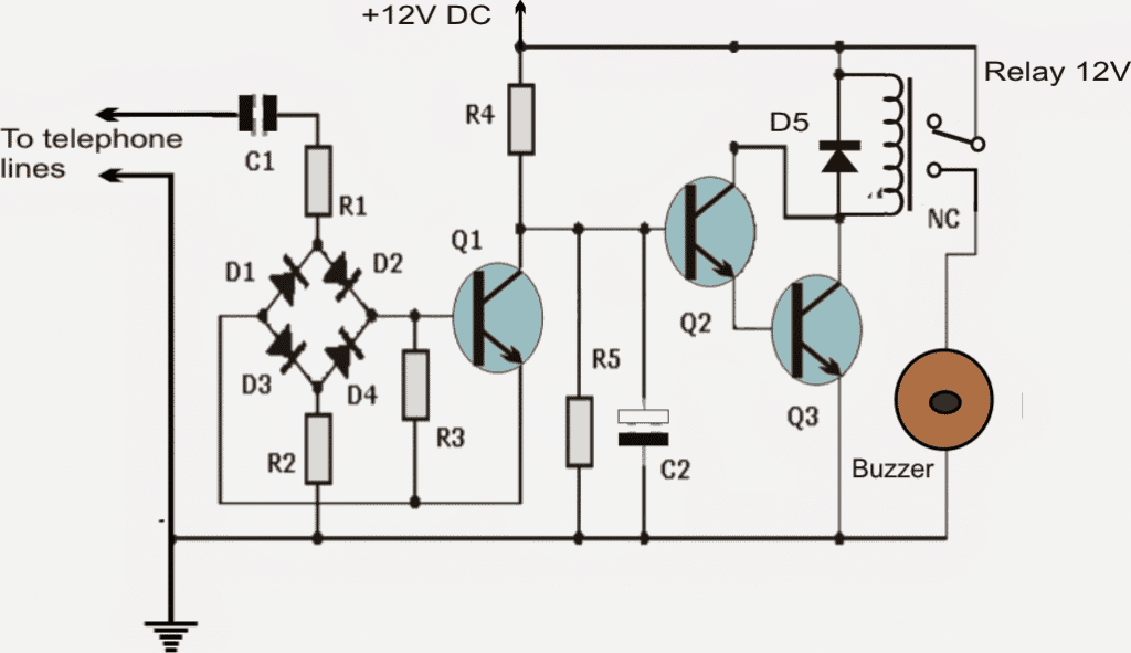
The signal is derived directly from the telephone lines. The current from the lines passes through a set of capacitor C1 and resistors R1, R2, R3 and a rectifier bridge formed by diodes D1, D2, D3, D4. Thus a filtered DC signal is achieved which is then applied to the base of transistor Q1 in the form of a positive pulse signal.

The transistor Q1 responds to the rhythmic pattern of the signal received at its base, resulting in an inverted and amplified signal across its collector resistor.

This amplified collector signal is restricted by the set of resistor R5 and capacitor C2 network making sure that the signal is not pulsed rather direct and straight.

This modified DC is then applied to the set of Q2 and Q3 transistors connected in Darlington configuration for further amplification so that the final output is able to actuate the relay to activate the buzzer. D5 is used to protect transistors Q2 and Q3 for reverse relay coil back EMFs.

Circuit Diagram
List of components for the proposed Telephone repeater circuit

- 2 transistors Q1, Q2: BC547B
- One transistor: Q3: BC337
- Five diodes D1, D2, D3, D4, D5 1N4148
- One capacitor C1: 0.033uF
- 1 electrolytic capacitor: C2: 1uF, 50V
- Two resistors R1, R2: 100K
- 1 resistor R3: 8.2K
- 1 resistor: R4: 180K
- 1 resistor: R5: 39K
- 1 relay (relay) 12V
- 1 12V loud buzzer

Caution: Do not reverse the polarity of the telephone wires to the repeater.

You'll also like:

  • hum filter graphSimple Hum Filter Circuit for Amplifiers
  • Table 1Parametric Equalizer Circuit
  • cartridge5 Simple Audio Mixer Circuits Explained
  • amp fuse protectorPrevent Amplifier Fuse from Blowing During Power Switch ON

Filed Under: Audio and Amplifier Projects Tagged With: Amplifier, Extended, Repeater, Ring, Telephone

About Swagatam

I am an electronics engineer and doing practical hands-on work from more than 15 years now. Building real circuits, testing them and also making PCB layouts by myself. I really love doing all these things like inventing something new, designing electronics and also helping other people like hobby guys who want to make their own cool circuits at home.

And that is the main reason why I started this website homemade-circuits.com, to share different types of circuit ideas..

If you are having any kind of doubt or question related to circuits then just write down your question in the comment box below, I am like always checking, so I guarantee I will reply you for sure!


Previous Post: « Simple Thermostat Circuit Using Transistors
Next Post: Make this Simple Music Box Circuit »

Reader Interactions

Discussion & Solutions

Total Posts: 2
Newest Oldest
STEFAN
July 10, 2022 • 4 years ago #131464

Good evening,
I have been following you for a long time and I especially appreciate your activity, which opened my appetite for electronics, but especially for multiples and extremely useful applications even for self-taught beginners like me.
But, related to the circuit described above, it reminded me that I have several electronic landlines, from which I would like to use parts of the assemblies (keyboard, amplifier, bell, etc.); can you help me with schemes of such devices?
Thanks

Reply
SwagatamAdmin
July 10, 2022 • 4 years ago #131473

Hi, sure, I can help you with common electronic circuits which can be built using common spare parts from electronic devices like telephones etc. If you can tell me which parts you have gathered I will try to figure out which small circuits could be built using those parts.

Reply

Need Help? Please Leave a Comment! We value your input—Kindly keep it relevant to the above topic! Cancel reply

Your email address will not be published. Required fields are marked *

Primary Sidebar


My Youtube Channel

Circuit Simulator

circuit simulator image


Subscribe to get New Circuits in your Email


Categories

  • Arduino Projects (95)
  • Audio and Amplifier Projects (134)
  • Automation Projects (18)
  • Automobile Electronics (103)
  • Battery Charger Circuits (88)
  • Datasheets and Components (109)
  • Electronics Theory (149)
  • Energy from Magnets and Earth (40)
  • Games and Sports Projects (11)
  • Grid and 3-Phase (20)
  • Health related Projects (27)
  • Home Electrical Circuits (13)
  • Indicator Circuits (16)
  • Inverter Circuits (99)
  • Lamps and Lights (162)
  • Meters and Testers (72)
  • Mini Projects (28)
  • Motor Controller (68)
  • Oscillator Circuits (28)
  • Pets and Pests (15)
  • Power Supply Circuits (91)
  • Remote Control Circuits (50)
  • Security and Alarm (65)
  • Sensors and Detectors (107)
  • SMPS and Converters (45)
  • Solar Controller Circuits (60)
  • Temperature Controllers (43)
  • Timer and Delay Relay (50)
  • Voltage Control and Protection (44)
  • Water Controller (37)
  • Wireless Circuits (31)


Other Links

  • Privacy Policy
  • Cookie Policy
  • Disclaimer
  • Copyright
  • Videos
  • Sitemap

People also Search

555 Circuits | 741 Circuits | LM324 Circuits | LM338 Circuits | 4017 Circuits | Ultrasonic Projects | SMPS Projects | Christmas Projects | MOSFETs | Radio Circuits | Laser Circuits | PIR Projects |


Recent Comments

  • Swagatam on 5 Useful Power Failure Indicator Circuits Explained
  • Swagatam on Simple 20 watt Amplifier Circuits
  • David Lloyd on 5 Useful Power Failure Indicator Circuits Explained
  • Dale on Simple 20 watt Amplifier Circuits
  • Swagatam on Blood Electrification Circuit: Explanation And Working Principle

Social Profiles

  • Twitter
  • YouTube
  • Instagram
  • Pinterest
  • My Facebook-Page
  • Stack Exchange
  • Linkedin

© 2026 · Swagatam Innovations