A very simple 2 watt audio amplifier circuit has been presented here which can be constructed by all new electronic hobbyists for amplifying small signal frequencies and for other similar experiments.
Circuit Operation
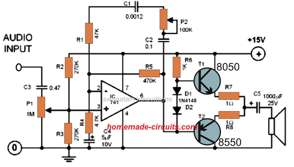
- This mini cellphone music amplifier circuit utilizes just a single IC 741 and a few other passive electronic components, making the entire working very easy.
- Being small doesn’t limit its dynamic features which can be compared to a standard amplifier specs. Though the power output is not more 2 watts only, becomes sufficient loud for applications like a radio pick up amplifier or a traveler’s ipod amplifier unit.
- The pot VR1 is used for adjusting the volume of the amplifier while the pot P2 is used for rectifying high frequency interventions if they are above 20dB. The IC 741 here actually acts as low gain amplifier and is responsible for stepping up the amplification just to a level that might be enough for driving the output power transistors.
- The two diodes D1 and D2 have a specific role and help to fix an ideal quiescent current level for both the transistors. The output transistors are arranged in a push-pull manner, as the name suggests they operate in tandem, generating a powerful push and pull of the amplified audio into the connected speaker.
Questions & Answers
What should I do make this circuit produce 200w from a 14v DC supply? Also what happens if the 8050 transistors were to be replaced with n channel MOSFETs?
I am not sure whether the amp can be upgraded to 200 watt simply by replacing the transistors. However, MOSFET will work in place of BJTs since the supply is 15 V.
For getting 200 watts at 14V would require current of 200 / 14 = 14 amps
can we connect this circuit with COB Audio circuit and get sweet sound.
I bought a Chinese New Year “Electronic Firecracker Display” It is quite interesting. We perform Chinese Lion Dances and at the end of the performance we press a button to set off the simulated fireworks display. Nice. Except they are not very loud and can barely be heard from 30 feet away with crowd clapping and yelling congratulations etc.
Can you recommend one of your circuits that I can build,, put a microphone near the firecracker speaker thingy and boost the sound with a bigger – stronger speaker?
Thanks in advance.
Dale
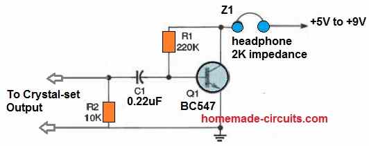
OK, you will have to first build a MIC preamplifier circuit such as this one:
Next, you will have to configure the output from the above circuit with the input of a power amplifier for the desired amplification. You can select any one of the following amplifiers as per the required power output specifications:
https://www.homemade-circuits.com/category/amplifiers/
yes you can use it, here are some more options:
https://www.homemade-circuits.com/lm4862-amplifier-circuit-better-lm386-alternative/
https://www.homemade-circuits.com/usb-5v-amplifier-circuit-for-pc/
https://www.homemade-circuits.com/6-watt-audio-amplifier-circuit-using/
https://www.homemade-circuits.com/ic-lm-386-datasheet-explained-in-simple/
I am in electronic Engineer student currently in 4th semester our teacher gave us project which is make audio amplifier using LM741 ic and power should between 5 to 50 watt can you please help me
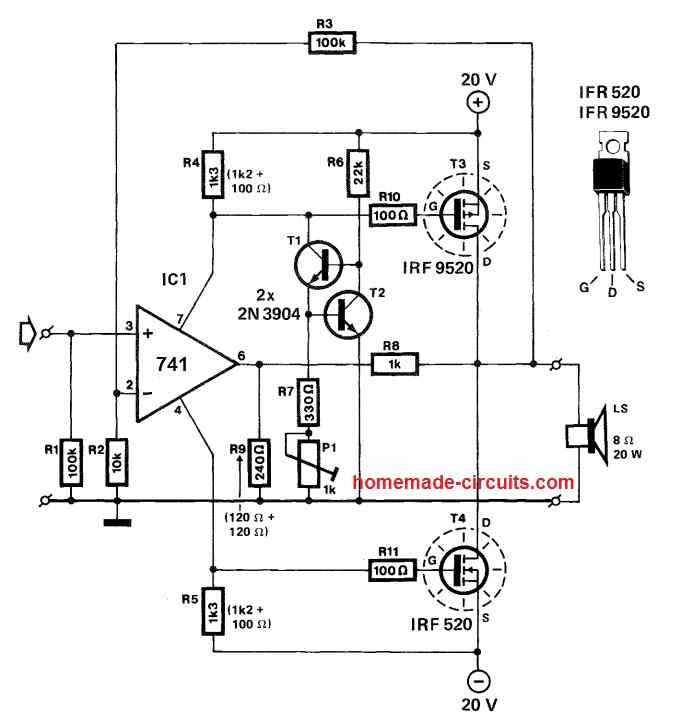
you can try the circuit explained above with some modifications. Change the 8050 to TIP122, and 8550 to TIP127, and reduce R7, R8 to 0.22ohm 2 watt.
Thank you sir for reply
i am sharing you project details,
IC Should be LM741 & LM324
PRE-AMPLIFIER
TRANISITOR should be Emitter follower.
and power between 5 to 50 watt
Hi EH, the above diagram is exactly as per your specifications.
Hello
I am an electronic student nd I must prepare my license project I choose creating an alarm security system with an pir detector a buzzer and a led
however my teacher asked me.to amplify the buzzer spund could I install this.circuit.to amplify d buzzer sound
You can use it, but I would recommend using a single IC based circuits such as these:
https://www.homemade-circuits.com/6-watt-audio-amplifier-circuit-using/
https://www.homemade-circuits.com/ic-lm-386-datasheet-explained-in-simple/
https://www.homemade-circuits.com/usb-5v-amplifier-circuit-for-pc/
Tnx
One more question pls if u don’t mind
If I decide to link this amplifier to a buzzer How much should b d current I(in)of d pin 3 that’s linked to a 1ok potentiometer
In other meaning should I use a current amplifier between d buzzer and d audio amplifier imput or reduce d current ou just link it directly
Please tell me which buzzer are you using, provide the current and voltage specifications I’ll try to help!
If your buzzer wattage matches the amp wattage, then no need of any other circuit in the middle. Make sure the buzzer wattage is less than the amplifier wattage rating
Hello
Well I am trying to Create a arduino based security system I started from studing a simple.circuit using an arduino uno ,an ir captor ,a buzzer and a led
However my teacher recommend me to increase d led brightness and amplify d sound of a buzzer or just change.it so I thought making an audio amplifier would b d best solution
If am mistaken pls recommend me a circuit that could b linked to my circuit
If you are using a piezo buzzer, it cannot be amplified, in fact buzzer with internal oscillator cannot be amplified. You will have make a small oscillator, then connect the output of this oscillator to an amplifier.
If your requiremenet is s simple buzzing sound, you an do it with a IC 555 astable oscillator and connect a 2 watt or 5 watt speaker through a transistor
you can try this:
Replace 5K pot with 100k pot, replace 1nF capacitor with 0.1uF, replace EM with a 5 watt speaker
By the way the right way to configure is to add an oscillator at the input of the amp and a speaker at the output. A readymade buzzer won’t work with an amplifier
Hi bro, can i use 9v battery for this ckt or whether dual pwr spply is required???
Hi Bro, dual won’t be required, a single power supply will do, but a 9V PP3 won’t last very long….
sir..
how can i numbering the pin of IC…
plz help me..
I wnt to make that circuit. Can the layout of this circuit also available. Please tell me Asap.
sorry PCB layout is not available.
Where will the 2nd input be?
My circuit isn't working
there's no second input, it's a mono amp.
Sir, Those non-electrolytic capacitor i'm not getting them, are they in f or uf?
For the pot 2; can i use 100k or 200k
those are in uF, for pot2 both will work.
Welldone sir.
Sir; I cant find Pot2 1M , i have 100k, should i fix 10k in series with d middle pin of the pot?
Is it neccessary to let the pot2 protrude out like the volume
thanks madamidola,
10k in place of 1M will not work, you will have to procure the labelled pots only.
P2 could be a preset or a pot and may be hidden, but if it's fitted outside like a pot it may give the unit an added feature.