The presented circuit of a musical greeting card circuit was requested by one of the keen readers of this blog, so I designed this interesting little circuit, which is simple and easily gets embedded inside any standard greeting card fold.
Looking at the given circuit diagram, we see a design consisting of a very few number of components, rigged via connecting wires.
The design may be understood with the following explanation:
Circuit Operation
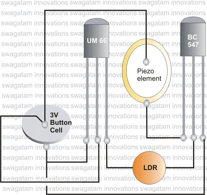
The main music generating component is the IC UM66, which has a digitally processed music data embedded inside it.
The IC just requires a 3 volt supply for reproducing the content over an appropriate speaker.
Since the output from the above IC is pretty low, it requires some kind of amplification before it can be practically heard, a transistor stage needs to be introduced.
The BC547 transistor performs this function well and is therefore positioned for amplifying the tiny music info inside the IC.
To keep things extremely thin and slim, a piezo is incorporated as the speaker as these devices require hardly any space to sit and also operate with nominal signal outputs.
The amplified music from the transistor is though not too powerful, is significant enough to drive the connected piezo element so that the user is able to hear it at reasonably good volume.
Now the main criterion with a musical greeting card is that, the music should play only when the card is opened and should shut off when it's closed.
In order to implement this we need some kind of trigger arrangement, a leaf switch could have been a good option, however employing an LDR looked more technical and solid state.
An LDR here becomes the base bias resistor for the transistor. When the card is opened, ambient light falls over the LDR lowering its resistance value which in turn switches the transistor and music starts playing.
The moment the card is closed, LDR is inhibited from the ambient light, it's resistance shoots up in Mega Ohms choking up the transistor conduction and instantly switches OFF the music from the piezo.
A 3V button cell becomes enough for sustaining the functioning of the system almost forever.
The entire shown circuit should be carefully fixed inside a good quality greeting card, making sure that the LDR is able to "see" the ambient light whenever the card is opened.

Questions & Answers
I am Jonathan I have created a doorbell from the circuit that amplifies the sound to a speaker with a hundred decimals and can be connected directly to a existing doorbell switch replacing your fashioned solenoid doorbell by reading your web thank you
Can you email me a diagram of how to put the components on a perf board as I’m a complete novice to electronics and have bought every tool and component and watched lots of videos on YouTube but still don’t know how to go about making circuits that could be easy to make…thanks in advance
Sorry, I do not have a diagram to show how to put components in perfboard. I think you can find the answer through YouTube videos, so I would recommend you to search this on Youtube.
Can you please contact on 9158846000 for providing me specialized musical greetings cards circuit in 8 to 10 days
Sorry, I don’t manufacture and sell electronic circuits from this website.
Where can I get the parts?
How do we connect the button cell?? Could you please upload the video?
scratch clean both positive/negative surfaces of the cell, apply little solder flux, and tin the area with little solder….after this you can connect flexible wire ends to these surfaces by soldering, and use other ends of the wire for supplying the circuit
How much does this COB cost? Need them in bulk.
around Rs 500/- for 100 pcs,
Dear Swagatam,
Can I get the programmable cob somewhere in Mumbai? Got to use it for my wedding cards in bulk quantity. Please help
Regards,
Manish Chavan.
Dear Manish,
Please inquire in Lamington Road, you'll surely find an appropriate guy who'll be able to do it for you.
Dear Sir, This COB is not available at my place and online sites. So, can this be made?
Thanks
Dear Ankit, In that case you might have to visit Mumbai…..sorry it cannot be made at home.
Dear Sir,
1.Can a circuit be designed (operating on 12V) which generates speaking sound such as "Welcome" or other simple sentences.
2.Further, as mentioned above, What is a COB, where can we get one.
Thanks
Dear Ankit, yes it can be done by using a COB which might have an embedded programmed audio to reproduce the particular length of speech.
COB or chip on board are programmed music or speech ICs available in electronic markets….for example in Lamington Road Mumbai
for a 12V circuit you might need elaborate modifications in the above circuit
which are programmable IC's? and can we put a switch instead of LDR? how much power it consumes?
you can use any 3V operated COB in place of the shown UM66 IC. consumption will be around 2 to 5mA