In this post I have explained a simple fused or blown car brake light indicator circuit using a single IC 555 and a few other passive components. The idea was requested by Mr. Joel Bayongasan
Technical Specifications
You innovations are great! Thanks for this blog. May I request something please? I was searching for a circuit that will detect a blown brake lamp.
A car normally, there two connected in parallel or sometimes four.
I am looking for a circuit that would light an led indicator if one of the bulbs is busted. I hope you can help.
Thank you.
The Design
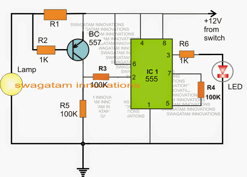
By introducing the above shown circuit between the lamp and the supply, the intended blown brake light bulb indicator can be easily built and implemented in any vehicle.
The functioning is quite straightforward:
The IC 555 is configured as a simple voltage comparator, where its pin2 becomes the sensing input.
The BC557 along with the associated R1, R2 resistors forms a current to voltage converter stage.
Using Resistor Sensor
As long as a working bulb lamp stays connected across the shown points, a small negative potential corresponding to the bulb current consumption is developed across Rx.
This potential becomes sufficient to keep the BC557 triggered and conducting which in turn keeps pin2 of the IC high.
With the above conditions, pin3 of the IC stays low and the LED remains shut off.
However in an event the car bulb fuses or stops illuminating, the potential across Rx vanishes or reduces to an extent where the BC557 just stops conducting.
This instantly renders pin2 of the IC high and the LED begins glowing indicating the blown brake light bulb situation to the user.
The above design can be also effectively used in many different applications which require some kind of current (amp) monitoring such as an over-current or over-load cut off etc.
R1 may be calculated as follows:
R1 = 0.7/bulb current rating
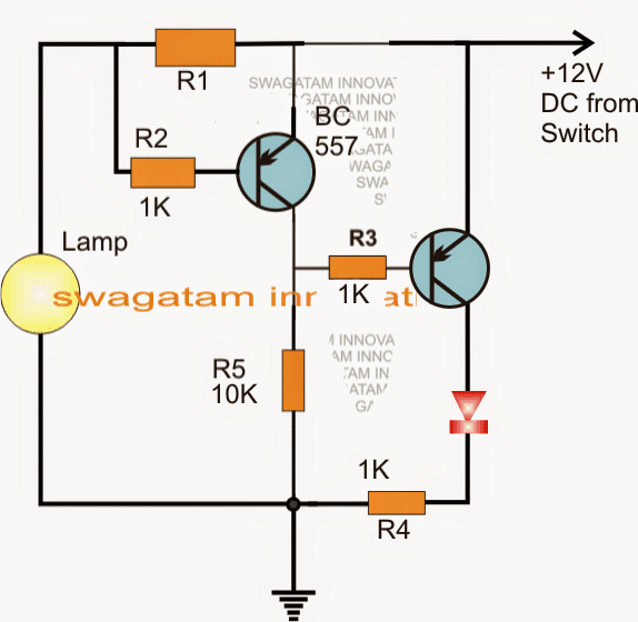
The above explained circuit can be much simplified through the following configuration:
Simplified Schematic
Using Reed Relay Switch
The above discussed blown car lamp, broken car lamp indicator circuit can be also implemented using a simple reed relay circuit as I have explained below:
How the Circuit Works
The reed circuit I have explained in this article, is made up only one reed-relay, a single LED and one resistor. It offers a less expensive blown lamp alert technique.
A LED is installed in a appropriate place around the dashboard, and it is switched OFF as soon as the concerned lamp malfunctions. It is obviously feasible to utilize many such circuits to keep track of various lamps or sets of lamps. The circuit (figure 1) functions by supplying the current to a lamp via the working coil of a reed-relay.
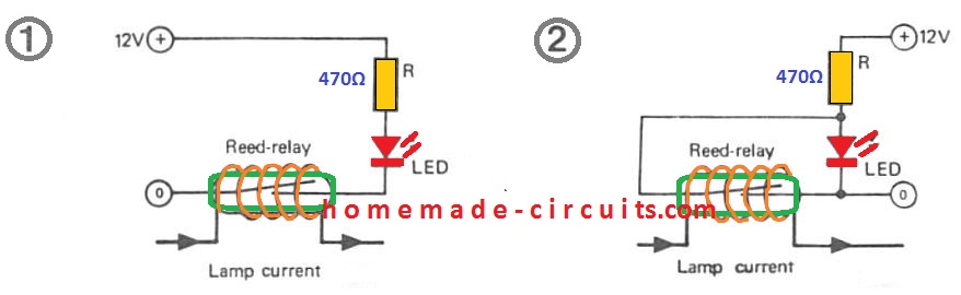
In case a specific lamp fuses, the current immediately drops, causing the reed relay to open up and switching OFF the LED. The quantity of wire turns on the working coil must be such that its closes the reed contacts efficiently through the standard working current of the lamp, and still small enough to ensure that the reed relay is able to opens out when of lamp happens to blow.
Usually, a reed relay needs around 30 to 100 AT (ampere turns = current x no. of turns). Therefore, considering the reasonably high level of currents utilized by car lamps, within this specific application the coil on the reed may contain just a few turns only. For instance, the two car headlamps pull a current of around. 7.5 A (at 12 V).
A reed-relay having specification of 50 AT might consequently need just seven turns to display the current of each headlamps. If either of the lamps burn, then the current via the reed coil drops to around one half, resulting in the reed to deactivate and the dashboard LED to become switched OFF.
The circuit demonstrated in figure 2 is an alternate model that makes the LED illuminate if a lamp requires replacing.
This allows a bolder warning specifically at nighttime. Nevertheless the circuit in figure 1 is also failproof.
To make sure that the caution technique works correctly, it's advocated that an independent reed relay is employed to keep track of lamps of varying wattage, i.e. separate reed switches for the back lights, brake lights, headlamps etc.
Additionally it is likely to utilize a solitary relay to screen each right and left turning signals with a double winding around the coil.
Nevertheless, it isn't recommended to make use of one particular relay to monitor a circuit or combined circuits that has in excess of two lamps can be ' turned ON ' at the same time, the circuit of figure 2 is utilized then the supply to the LED must be obtained from the switched part of the lamp supply.
This makes sure that when the relay disconnects out because of the lamp getting powered down the LED doesn't illuminate, because its power is additionally shut off. It is essential to notice that the winding thickness employed to wrap the relay coil must be a minimum of as heavy as that found in the actual car wiring, to reduce the voltage drop over the coil and likely overheating.
Brake Light Failure Monitor Circuit
Below shown is another blown brake light indicator using the IC NE555 timer. When the two brake lamps are functioning, the lamp LP remains illuminated. However when any one of the lamps or both the brake lights tend to be burn creating an open circuit the lamp LP begins blinking at 2Hz frequency, which is enough to signal the driver regarding a brake light failure.
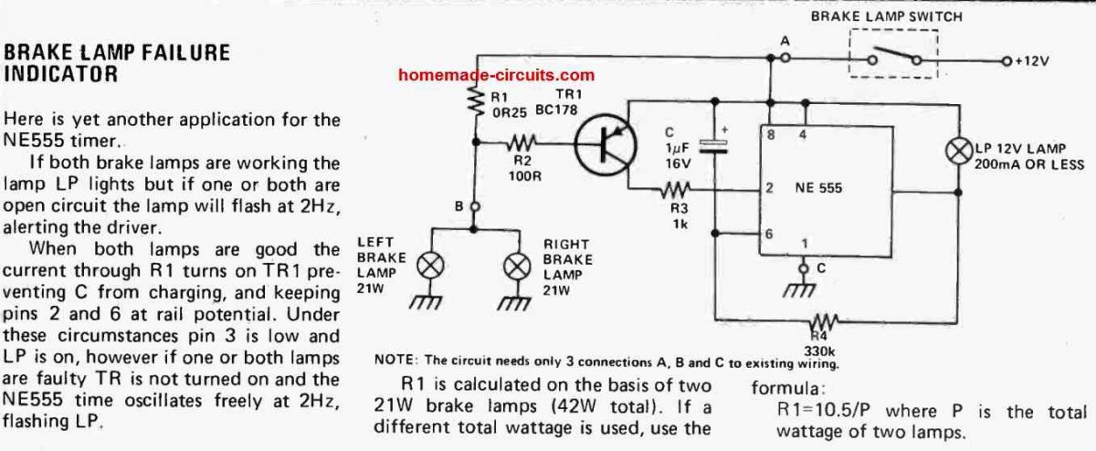
When both the rear lamps work in a sound condition, the current passing by means of R1 activates TR1 blocking capacitor C from charging, which allows the pins 2 and 6 at the supply potential. In these situations pin 3 of the IC is held low which keeps lamp Lp illuminated. On the other hand if a single or the two lamps become faulty TR does not get switched on, which allows the NE555 IC to oscillates continuously at 2Hz, causing the lamp LP to flash.


Discussion & Solutions
Thanks a lot!
Okay sir.Thank you so much.
Good day!i am doing this project.My only problem is the led light still remains on when i connect and disconnect it to the lamp.can anyone help me?thanks…
which circuit did you try? you will have to calculate Rx properly and make sure that it develops around 1V across it
I have tried the 1st circuit with ic555 and one more thing is:
1) i have used the L.E.D. brakelights instead of filament bulb for the lamp.
2)my led brakelight is 0.07ampere so i got 10ohms for my r1.
3)If i want to use filament bulb,how many watts of bulb should i use?Thank you.
you can use the bulbs which are normally used in motorcycle break lights, the auto spare part shopkeeper will be able to guide you correctly
I see…One more thing sir,is it only one bulb used in this circuit ?Thank you.
a motorcycle break-light will have only one lamp so yes only one bulb is shown here…
Hi! Great tutorial!
How about if the bulb would be power up by 220v in AC? Which modifications I have to do? Thank you so much!
Thanks, it can be done by replacing the sensing resistor and the associated transistor with an opto-coupler, bridge rectifier and a sensing resistor
Could you explain the calculation of the R1 resistor, is that R1=0.7 divided by bulb wattage, ie a 5 watt tail lamp, equals 0.14 ohm.
R1 = 0.7 / bulb current
If I want add this bulb light indicator in my car(12v) ,how I do this circuit on the vehicle.
Hi.
Great article. I was going to mention the reed relay method as I have used this many years ago on several cars I have owned. But I see you saved me the trouble.
I got a reed relay from Tandy (MANY years ago, 40+!) and simply wound the brake light wire that came with the car, around a 2 inch reed switch. There was a section of wiring that had enough slack to allow me to do this. When I pressed the brake, the current through the wire was sufficient to energise the reed switch.And I didn’t need to make sure my wire was thick enough, and because the wire was standard to the car, the voltage to the brake light was the same as standard.
An added advantage of this is the reed switch can be placed under the dashboard near the brake pedal (or anywhere the brake light wires are) and so no need to run long wires to the brake light/s (or anywhere).
I also used this principal when I designed an built a drag racing timing system. I installed a reed switch with a few turns of 240 volt wiring warpped around it (one in each dragstrip lane) to sense when the cars reached the finish line. A simple 240Volt sensor and finish light was installed at the finish line (one for each lane, with seperate actives). So when the cars finished, the finish light came on, drawing current through the reed switch winding, energising the reed switch. This was fed into the timing system to measure ET.
Hi, thanks, yes I agree reed switches are indeed very handy for quickly implementing small projects like the above. Appreciate your valuable feedback.
Hello dear Swagatam!
I’m looking for a bulb check circuit for years, and I found yours here. It is very good, but…
Any controly circuits I found knew one thing. They can check if a lamp is working, or can check the lamp is blown.
I’m thinking on a maximalist control circuit. I thought when I push the brake pedal and the lamps are working, it should give back a green light, and if the lamp blows out, then it should give a red signal. I have modified your first drawing (circuit with 555 ic), with an npn and a pnp transistor on the ic output, and I hope, it may work. 🙂 One of the transistors switches the green, the other switches the red check led.
Could you drop a look at my drawing anyway? Here I can not post my drawing. I draw it in Eagle.
My disatvantage is I’m not experienced in electronics, I’m only a hobbyist.
Thank you for your attention in advance.
Thank you Hajdubela,
If you want to show your diagram, you can upload it to any “free image hosting site” and send me the link here, I will check it out. Makes sure to remove the https from the link while sending it here.
Hello dear Swagatam!
Here I’m sending the link to my drawing.
I wasn’t give values to the R6-7-8-9, because I did not want to write numb numbers. 🙂
Please evaluate my idea, and solution, to check in one step the working, and faulty rear lamps.
Hello Hajdu,
Your circuit looks correct to me except the R1 resistor.
R1 must be positioned exactly as shown in the first diagram of the above article.
You can also remove the emitter resistors of Q2, Q3, they are not required.
Actually the transistors are simply not required. The two LEDs can be configured directly across pin#3 of the IC for the indications.