• Skip to main content
  • Skip to primary sidebar

Homemade Circuit Projects

Need circuit help? Post them in the comments! I've answered over 50,000!

Blog | Categories | About | Hire Me | Contact | Calculators-online
You are here: Home / Electronics Theory / Capacitive Voltage Divider Calculator

Capacitive Voltage Divider Calculator

Last Updated on October 21, 2026 by Swagatam 2 Comments

This capacitive voltage divider calculator helps us to find the C1 and C2 capacitor values for dividing an AC input voltage into a lower AC output voltage. We just have to enter the input AC voltage and the required output AC voltage. We also have to enter the AC frequency and the assumed AC current for which we want to calculate the capacitor values.
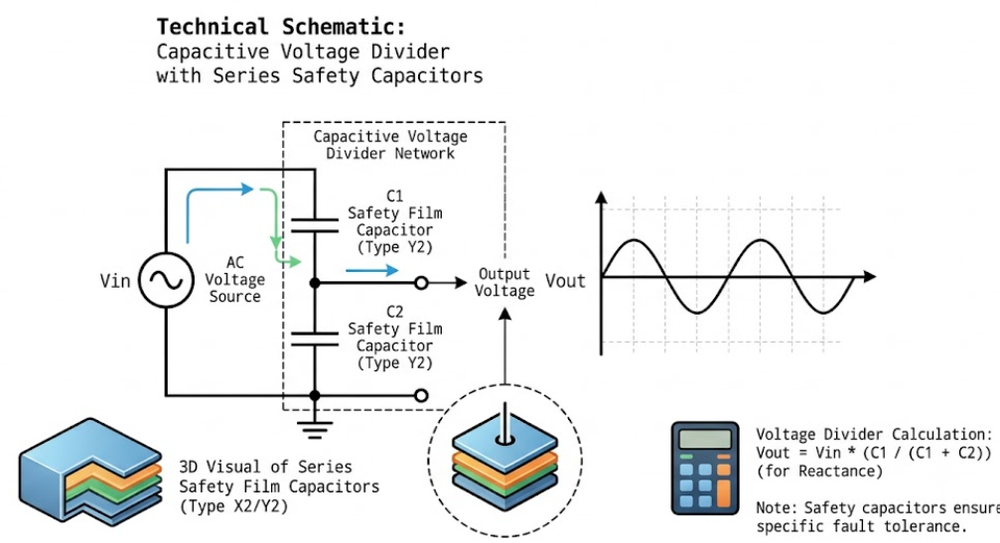
Table of Contents
  • Capacitive Voltage Divider Calculator
  • How it Works
    • Difference Between Resistive Voltage Divider and Capacitive Voltage Divider

Capacitive Voltage Divider Calculator

This calculator finds the theoretical capacitor values required to divide an AC voltage using two capacitors connected in series.

Safety warning

A capacitive voltage divider does not provide electrical isolation. Its output voltage can change with the load. The calculations below are based on an ideal unloaded divider and do not certify a circuit as safe for practical use.

Enter the values and click Calculate.

The calculator uses the ideal unloaded voltage ratio Vout / Vin = C1 / (C1 + C2). The assumed current sets the theoretical capacitance scale.

Actual output voltage and current depend on the connected load and circuit conditions. The calculated values are theoretical and are not a substitute for proper circuit design.

How it Works

After entering all the values we can click the calculate button and the calculator will show us the required C1 and C2 values in microfarads.

C1 is connected in series with the AC input supply and C2 is connected between the output point and the return line. Both capacitors work together to divide the AC voltage. The ratio between these two capacitors decides how much voltage will appear at the output point.

The input AC voltage and output AC voltage decide the required voltage ratio. The frequency also affects the capacitor values because the capacitive reactance changes with frequency. The assumed AC current is used to decide the approximate size of the capacitors.

For example if we enter 230V AC input and 110V AC output along with 50Hz frequency and 50mA assumed AC current then the calculator will work out the theoretical C1 and C2 values for these conditions.

The calculated values are only for an ideal unloaded capacitive divider. When we connect a load to the output the voltage can change and the actual current may also be different. So these values should not be taken as guaranteed working values for a practical circuit.

One important thing to remember is that this type of capacitive divider does not provide electrical isolation from the mains supply. So the output can be dangerous even when the voltage looks low. So the calculator is mainly meant for understanding the capacitor voltage divider principle and doing theoretical calculations.

Difference Between Resistive Voltage Divider and Capacitive Voltage Divider

Resistive voltage divider: This uses simple resistors and basic ohms law. For DC, it drops voltage nicely depending on the resistor ratio. For AC, it works too but the moment you hook up a real load to the output, then that load draws current and messes up the resistor balance, dragging your output voltage down. Also resistors turn that extra voltage into heat, so they waste a lot of power.

Capacitive voltage divider: They use capacitors instead of resistors. For DC, it blocks it completely because once a capacitor charges up to the DC voltage, it stops all current. It only works with AC because AC keeps oscillating back and forth which creates a kind of resistance called capacitive reactance. But it has big dependencies: it depends entirely on the frequency, so a circuit built for 60 hz will give a different voltage on 50 hz. And just like resistors, if you put a load on it, the output voltage collapses because the output impedance is very much high.

You'll also like:

  • digital bufferDigital Buffer – Working, Definition, Truth Table, Double Inversion, Fan-out
  • howtostopmosfetfromburningHow to Protect MOSFETs – Basics Explained
  • current sensor circuit moduleHow to Make Adjustable Current Limiter Circuits
  • arduino ledLearning Basic Arduino Programming – Tutorial for the Newcomers

Filed Under: Electronics Theory Tagged With: Calculator, Capacitive, Divider, Voltage

About Swagatam

I am an electronics engineer and doing practical hands-on work from more than 15 years now. Building real circuits, testing them and also making PCB layouts by myself. I really love doing all these things like inventing something new, designing electronics and also helping other people like hobby guys who want to make their own cool circuits at home.

And that is the main reason why I started this website homemade-circuits.com, to share different types of circuit ideas..

If you are having any kind of doubt or question related to circuits then just write down your question in the comment box below, I am like always checking, so I guarantee I will reply you for sure!

Previous Post: « Basic 555 IC Inverter Circuit Diagram Explained: 12V DC to 220V AC
Next Post: Capacitive Dropper Calculator Tool for Transformerless Power Supplies »

Reader Interactions

Questions & Answers

Total Posts: 2
Newest Oldest
David
October 24, 2026 • 7 hours ago #213823

How do I know how much continuous RMS voltage or continuous RMS current it can handle?
I assume there is a way it can be done with any type of capacitor if an additional fuse or current limiter is used?

Reply
SwagatamAdmin
October 24, 2026 • 3 minutes ago #213836

Every capacitor will have a voltage rating, so you just have to make sure the input AC peak voltage spec is well below this max voltage rating of the capacitor.

Reply

Need Help? Please Leave a Comment! We value your input—Kindly keep it relevant to the above topic! Cancel reply

Your email address will not be published. Required fields are marked *

Primary Sidebar

Categories

  • Arduino Projects (95)
  • Audio and Amplifier Projects (134)
  • Automation Projects (18)
  • Automobile Electronics (104)
  • Battery Charger Circuits (90)
  • Datasheets and Components (109)
  • Electronics Theory (153)
  • Energy from Magnets and Earth (43)
  • Games and Sports Projects (11)
  • Grid and 3-Phase (20)
  • Health related Projects (27)
  • Home Electrical Circuits (13)
  • Indicator Circuits (16)
  • Inverter Circuits (104)
  • Lamps and Lights (171)
  • Meters and Testers (72)
  • Mini Projects (28)
  • Motor Controller (68)
  • Oscillator Circuits (30)
  • Pets and Pests (15)
  • Power Supply Circuits (92)
  • Remote Control Circuits (50)
  • Security and Alarm (65)
  • Sensors and Detectors (107)
  • SMPS and Converters (46)
  • Solar Controller Circuits (62)
  • Temperature Controllers (44)
  • Timer and Delay Relay (51)
  • Voltage Control and Protection (44)
  • Water Controller (37)
  • Wireless Circuits (31)

People also Search

555 Circuits | 741 Circuits | LM324 Circuits | LM338 Circuits | 4017 Circuits | Ultrasonic Projects | SMPS Projects | Christmas Projects | MOSFETs | Radio Circuits | Laser Circuits | PIR Projects |

My YouTube Channel

Circuit Simulator: Draw and Simulate Schematics

circuit simulator image

Subscribe to get New Circuits in your Email

Other Links

  • Privacy Policy
  • Cookie Policy
  • Disclaimer
  • Copyright
  • Videos
  • Sitemap

Recent Comments

  • Swagatam on Capacitive Voltage Divider Calculator
  • Swagatam on Resistive Voltage Divider Calculator
  • David on Capacitive Voltage Divider Calculator
  • David on Resistive Voltage Divider Calculator
  • Swagatam on True MPPT Solar Controller Circuit using IC 555

Social Profiles

  • Twitter
  • YouTube
  • Instagram
  • Pinterest
  • My Facebook-Page
  • Stack Exchange
  • Linkedin

Calculators

  • ZVS Induction Heater + Tank Calculator Tool
  • Zener Diode Calculator
  • Wire Current and Thickness Calculator (Ampacity Calculator)
  • Resistive Voltage Divider Calculator
  • Transistor Base Resistor Calculator
  • Transistor Astable Multivibrator Calculator
  • TL431 Calculator
  • Solar Panel, Inverter, Battery Calculator
  • Ferrite Core Air Gap Calculator Tool
  • Parallel MOSFET Calculator Tool: How to Connect MOSFETs in Parallel Safely
  • LC Resonance Calculator for EV Battery Charger Circuits
  • LED String Series Resistor Calculator
  • PFC (Power Factor Correction) Calculator Tool: 3kW
  • Passive Power Factor Correction (PFC) Calculator
  • LM567 IC Calculator Tool
  • SMPS Flyback Boost Converter Calculator
  • Shunt Resistor Calculator for Ammeters
  • SCR and Triac Gate Resistor Calculator
  • Battery Back up Time Calculator
  • Boost Converter Calculator (Non-Isolated)
  • Bootstrap Capacitor Calculator
  • Buck Converter Calculator
  • Buck-Boost Converter Calculator
  • Capacitance Reactance Calculator
  • DCM Flyback Transformer & Wire Gauge Wire Size Calculator Tool
  • Filter Capacitor Calculator
  • IC 4047 Calculator (Frequency and PWM)
  • IC 4060 Calculator
  • IC 555 Astable Calculator
  • IC 555 Monostable Calculator
  • IC SG3525, SG3524 Calculator
  • Inductance Calculator
  • Induction Heater Inductor and Resonant Frequency Calculator
  • Induction Heater Work Coil Calculator
  • Inverter LC Filter Calculator
  • LC Resonance Calculator
  • LED Current Calculator
  • LM317, LM338, LM396 Calculator
  • NAND/NOT Gate RC Values Calculator
  • NOT, NAND Gate Frequency Calculator
  • Notch Filter Calculator Tool
  • Ohm’s Law Calculator
  • Phase Angle Phase Shift Calculator
  • Power Factor (PF) Calculator
  • RC Filter Calculator
  • Reactance Calculator
  • Sine Table Calculator for SPWM Arduino Code
  • Small Signal Transistor(BJT) and Diode Quick Datasheet
  • SMPS Calculator for Toroidal Ferrite Transformers
  • SMPS Flyback Transformer Calculator – Design by Target Duty Cycle
  • TL431 Calculator
  • Op-Amp Hysteresis Resistor Calculator

© 2026 · Swagatam Innovations