In this post I have explained a simple LED flashing beacon circuit which exactly simulates a rotating police beacon light by generating alternating pulses of suddenly rising and fading illumination effect on the connected LED. The idea was requested by Mr. Ankit Agarwal
Technical Specifications
Can you advice on how to make the following circuit A single flashing LED circuit, in which the LED flash simulates that of beacon ie when the LED flashes, first it glows slowly, then to full intensity, and then fades.
This gives the effect of a rotating beacon OR just like the lights on an aircraft tail.The circuit is intended to be used in the car (as a flashing rear light) so the circuit may function on 12v and the LED may be bright enough to be visualized clearly so it may be 1 watt smd led.
Kindly advise
Thanks
The Design
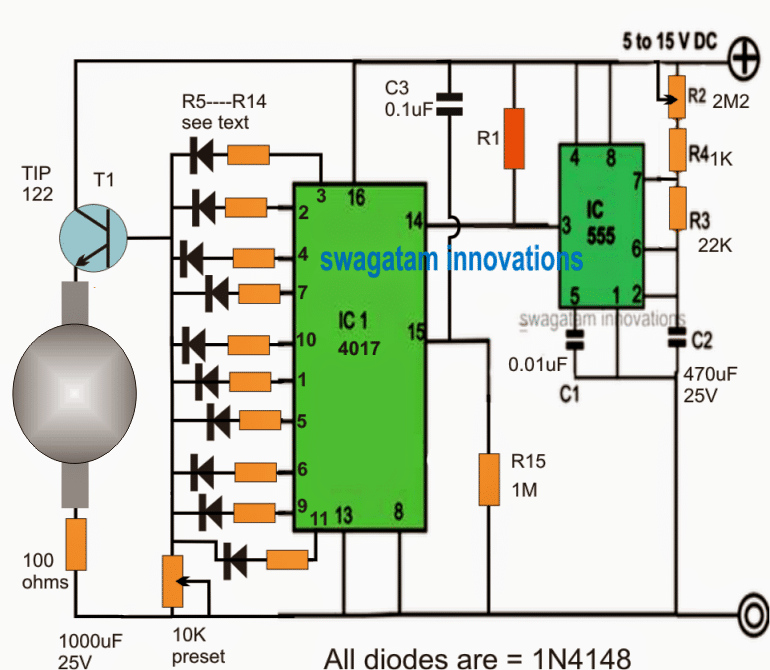
The proposed idea of a single LED rotating beacon lamp simulator can be implemented using the above shown circuit.
Here the IC 4017 and the IC 555 together are configured to generate a sequential chasing high logic across the 10 pinouts of the IC 4017.
The IC 555 is wired as a standard astable which feeds the clock or the flashing signal at pin14 f the IC 4017.
The IC 4017 responds to these clocks and generates a shifting high logic across its 10 outputs from pin#3 to pin#11.
These pinouts are integrated via individual diodes, and the common terminal can be seen connected with the base of a TIP122 transistor.
This transistor includes a 1 watt LED across its base emitter points which enables it form an emitter follower configuration with the LED.
This means that the LED will be supplied with a voltage level that may almost equal to the base voltage of the TIP122, and if this varies, the LED supply can be expected to vary accordingly.
The resistors connected across all the shown outputs of the IC 4017 is selected with an incrementing order or in way such that it forms an incrementing potential divider with reference to the preset resistance which may be seen across the base and ground of the TIP122.
Therefore as the 4017 IC generates the shifting or chasing high sequence across its pinouts, the resistors with reference with the preset resistance value generates a correspondingly increasing or decreasing potential difference at the base of the TIP122 transistor.
This effect in turn allows a varying potential difference to develop across the LED, which responds to this and produces the required sudden rise and decay effect and viec versa on the LED simulating a rotating beacon light.
The speed at which this happens can be set or adjusted with the help of R2.
The light intensity on the LED can be adjusted by suitably setting up the preset at the base of the TIP122 transistor.
The values of the resistor across the pinouts of the IC 4017 may be selected and swapped as per the user preference for generating different random flashing effect with due experimentation.
A rough simulation effect of the above explained rotating beacon simulator circuit using LED may be witnessed as given below.
An easier and cheaper alternative for a revolving LED beacon light can be seen below, although the effect may not be as impressive as the above design.
Please note that you may have to play with the 10K, 1K and the capacitor values to get the most desirable revolving lamp effect from the above circuit.
Simple Emergency Flasher
The next emergency lamp flasher can be used for distress calling, during a car accident or car breakdown:
A 3 LED Police Light Beacon can be also simply built using the following 4017 IC based circuit:
Simple Solar Beacon Strobe Light Circuit
This is a simple solar flashing strobe light circuit, which is self sustained. It will charge the battery automatically during daytime using sunlight, and the stored energy in the battery can then be used at night to power the flashing beacon.


Questions & Answers
Similar effect can be achieved by comparing two triangle waves, one at blink frequency, the other at a high enough frequency not to see the flickering. The output of the comparator is a pwm signal that rises and decreases with the lower frequency period. You can adjust the duty cycle by offsetting either wave with a DC component prior to the comparator. I used this to simulate a rotating beacon on a model aircraft to achieve a close simulation to the beacon on my real airplane which is actually a flashing incandescent bulb.
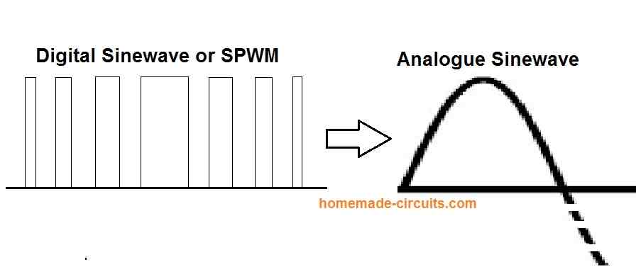
Yes, the output will be actually an SPWM (rough sine wave equivalent) with the following waveform, and will imitate a rotating beacon effect nicely.
I am a 79 year old modeler. Can I expand the three LED beacon to six or eight LED’s? I want to attempt to create some effects on my star ships. Thanks
Hello, Yes, you can do that, just make sure to connect the 1M from pin#15 with the pinout that comes next to the last pinout for the LED.
Also, you can try connecting a 100uF/25V capacitor across each LED to give it a fading ON/OFF effect.
I am looking for a relatively low priced app or pc program in which I can design circuits using 4017 IC and 555 and other ICs. I would then like to simulate the operation of that circuit. Any help?
There are actually plenty of them, you can search it online, you may come across many options.
Thank you so much for the help you have provided so far. I have another circuit I’m looking for.
I am in search of a group (5 on each side) of yellow/amber LED (smd) that start in the middle and sequentially light up to the outside.
Thank you.
Thank you! You can try the following design:
For the 3 led police light beacon what kind of 4017 IC is used?
All types of 4017 ICs will work.
Thank you.
Hello. I am looking for a circuit that does not require coding to make 3 small LEDs flash in sequence. When they are placed together they will create a rotating effect as in an old police light beacon.
Hi, you can try the following circuit:
Thank you for the website! Very educational for a novice like me. I’m looking for a circuit that will “fade” up a single LED and then “flash” at the end of the sequence. Imagine a laser cannon building up power then firing. I believe this circuit will accomplish this with the exception of only wanting the sequence to run one cycle until it is manually reset (a button is pushed). Is there a better alternative circuit.
Thank you, and glad you liked the website. Do you mean, the LED must first illuminate brightly, then fade, then flash, then manually reset for a new cycle?
Just the opposite. Start off dark then gradually brighten with a flash once it reached the brightest illumination.
I have designed it, you can see it in the following diagram:
Thank you! I’ve compared this with the original design and now have a better understanding.
Thanks! Glad to help!
First of all, thank you for putting this out here and helping fellow enthusiasts. I was wondering if there is a video of the actual circuit running? Before buying the parts and building it, I’d like to make sure the effect is what I am looking for. Thank you.
There’s no video at this moment, however The circuit should work perfectly according to my understanding.
Appreciate if you could update the circuit achording to comments.Hence we can assemble without hazzle.Expecting the updation soon.
I have updated the drawing at the bottom of the post!
Sir,
Thanks for your prompt and swift reply. My requirement was bit different, ie, two numbers of LED lamps of 10 Watts each working in a flip flop manner. kindly suggest the modification to be carried in your given circuit.
Thanks
Pradeep, you can try the following concept:
https://www.homemade-circuits.com/led-obstruction-light-circuit/
Eliminate the entire LDR stage along with D1/D2.
And replace R9/R10 with 10uF capacitors for getting a slow fade effect
Sir,
Can I have a modified version of above rotating beacon circuit with two numbers of 10 watts or less LED lamps with adjustable/selectable On/Off (ie 20 or 30 flashes etc) period?
Hi Pradeep, you can use two TIP142 in parallel and put two 10 watt LEDs at their emitter terminals for getting the effect. For speed adjustments you can tweak the R2 pot.
que valores son las resistencias 5 17
You can use 1K for R5—R14
Can I connect a 6no 4pin RGB LEDs in place of 1Watt led. What modification to do for that?
please first build and confirm with a 1 watt LED then we will proceed with RGB
Cuyler, sometimes this happens, if you refresh the page and try then mostly it will start loading normally again, anyway I am glad you found the solution
Swagatam, this post section was not loading and I posted my question in the simple wind generator post.Now I think I have my answer after reading Nelio's comments! Thanks for your time
Hi,
In the original circuit you miss a 1000uF capacitor, but present in the simulation! Is it needed? Since I'll be using 2 standard LED's, can I replace TIP122 by another ref., smaller, that can withstand both LED's?
Best Regards.
Nélio.
the 1000uF could be experimented for smoothing the fading effect, although it's not so crucial….
Hi,
Thanks for your replay. I remember this circuit. Replacing R5-R14 with trimmers what would be the maximum value? 10K? Considering TIP122, I can connect 2 LEDs in series, right?
Best Regards.
NA
Hi, yes the preset can be 10K, it's basically for setting up the base voltage for the TIP122 such that it varies from the minimum LED fwd drop value to the max LED fwd drop value….for two LEDs this could be from minimum 5V to a maximum 7V
the above range should be uniformly distributed across the 10 outputs of the 4017.
Hi Swagatam,
What is the value of R1 in the circuit?
Best Regards,
Nélio.
Hi Nelio, R1 is not required, you can do without it, I lifted the drawing from one of my other application designs, and forgot to remove it for this design.
Thanks you sir for answer.
Hello sir,
Please sir can you modify this
Circuit to controll Ac 220volt bulb
Ubaid, it can become much complicated due to the inclusion of a PWM stage and a MOCxx opto coupler stage…
Sir I am interested in circuit design. I want to know more from you .
Dear Swagatam
Please inform the function of R1, C3, R15 and 1000µF.
Dear Abu-Hafss,
the 1000uF is not required, I forgot to remove it in the simulation.
C3 is for resetting the IC 4017 on power switch ON, but here this may not be required so it may be removed…R15 is for enabling the C3 resetting action, therefore it can also be removed and pin15 can be directly connected to ground
Dear Sir, many thanks for promptly building the schematic.
If the desired effect is 1 cycle of flash then a pause for 10-15 sec or more, then again a cycle of flash and so on, what probable alteration shall be done in the component values
you can add the last circuit from the following link and use it to keep the above circuit switched OFF during daytime
https://www.homemade-circuits.com/2012/01/how-to-make-light-activated-day-night.html
Can an LDR be added in this circuit so that the flasher functions automatically after dark.
Kindly advise
Dear Ankit, for that you may do the following steps:
remove the diode and resistor from pin11, and make it blank
next, connect pin13 to ground through a 2.2M resistor
Now connect pin11 with pin13 via a 470uF capacitor, (+) to pin11, (-) to pin13