In this post I have explained how to assemble IC 555 for generating interesting LED circuits with blinking, flashing and fading light effects with some minor modification and enhancements.
Why use an IC 555 Astable
The astable multivibrator mode is the most fundamental mode of operation of the IC 555. In this mode it basically functions like a free running oscillator. If this oscillator rate is reduced sufficiently, can be used for driving LED lights.
The wiring at the output can also be further modified for achieving interesting variations and light illumination patterns over the connected LED.
Some of the practical ways of this is explained here, circuits diagrams of LED flasher, ghost effect generator, alternate blinker, light fader etc are also included.
In this article I have explained a few interesting and simple LED blinker circuit configurations using the ubiquitous IC 555.
The basic flashing mode has been kept intact yet various different attributions are provided to the circuit with its flashing rate and pattern.
The IC 555 is a complete package for the hobbyists. You can build numerous interesting circuits with this chip and make it to work as virtually any way you desire.
Though the circuit provides us with many application ranges, flashers configurations are more commonly associated with these chips.
These can be made to blink all types of lights at different rates depending upon individual preferences.
You can flash LEDs, torch bulbs, string lights or even mains AC lamps with circuits incorporating this IC.
Basically, to configure the IC as a flasher or blinker, it’s connected with its fundamental astable mutivibrator mode.
This configuration in fact requires just a couple of resistors and a couple capacitors to kick start the said functions.
Once the chip is assembled as an astable, we can go ahead and enhance the output in many different ways to get outstanding visual treats.
Let’s learn how a few fabulous IC 555 circuits with LED can be built with the following discussions, but first we would like to know what materials are needed for this.
Being a hobbyist you would want to have a bunch of assorted resistors in your box of goodies and also some selected values of capacitors.
For the present projects you would require a handful of different value resistors and capacitors.
Parts List for the proposed flasher and fader circuit using IC 555
- Resistors rated at ¼ watt, 5 %, unless otherwise stated.
- Resistors – 1 K, 10 K, 680 Ω, 4.7 K, 100 Ω, 820 Ω, 1 M etc. = 1 each
- Capacitors – 0.01 µF, 470 µF, 220 µF, 1 µF = 1 each
- Zener diode – 5.1 volts, 400 mW = 1
- LEDs – Red, Green, Yellow 5mm
- IC 555 = 1
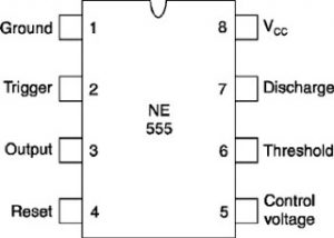
IC 555 Pinouts
Video Demo
Creating Flashing and Fading LED Effects using IC 555 Circuit
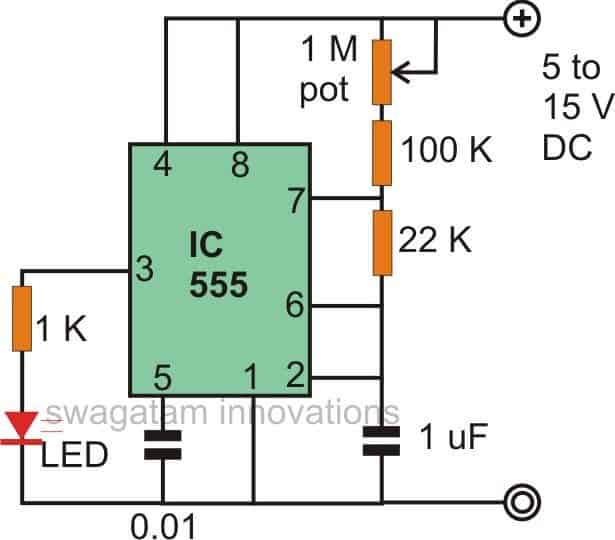
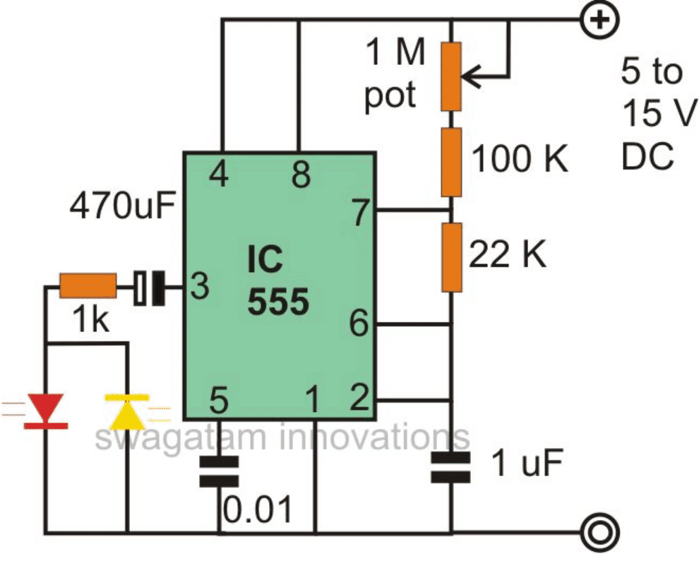
The first figure shows the basic configuration associated with a 555 IC LED circuit. Here it is connected as an astable multivibrator.
The resistors and the capacitor 1 uF can be experimented with to get different rates of blinking over the connected LED.
The LEDs can also be used with other colors.
The 1 K resistor can be replaced with lower values for increasing the intensity of the LED, however it should not be reduced below 330 Ohms.
Alternatively the 1 M resistor can be interchanged with a pot for attributing the circuit with variable blinking rate feature.
Making a Police Revolving Light Effect
The above circuit can be suitably modified for producing a revolving, flashing police light effect to the above constructed circuit.
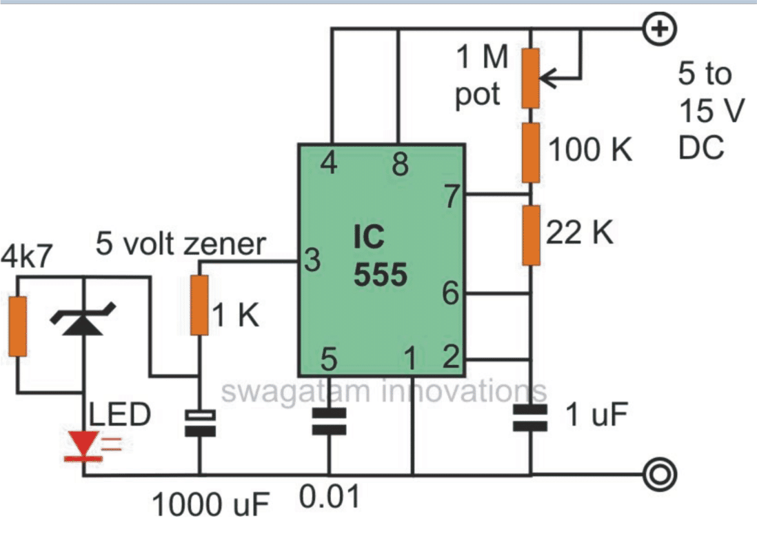
Here by adding a network of a zener diode / resistor / capacitor, to the output of the circuit, just as shown in the figure, we can acquire a very peculiar effect with the generated illuminations of the LED.
The LED initially glows bright, then slowly dies down, but intermittently gives a high intensity pulse producing the discussed police warning roof light indicator illusion.
Random Light Effect Generator Circuit
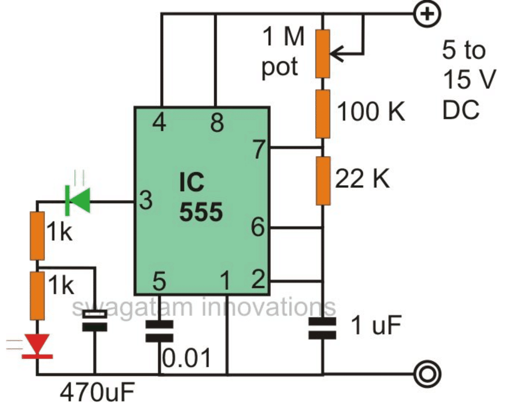
The 555 LED configuration shown in this figure enables us to use the circuit to generate random light patterns over the connected group of LEDs.
As shown, three LEDs are connected in conjunction with a couple of resistors and a capacitor.
The two LEDs connected in parallel but with opposite polarity, flash alternately at a particular rhythm while the third LED fluctuates at some other random rate.
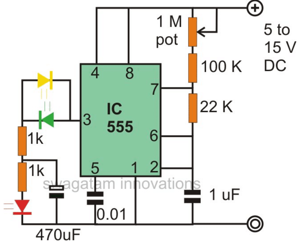
The above effect can be simplified by the circuit shown below.
Here, the LED which is connected to the 1 K resistor blinks at the fixed blinking rate, but the next LED which is connected to the ground switches rapidly at some other defined rate.
Adding a Spooky Effect to the LED
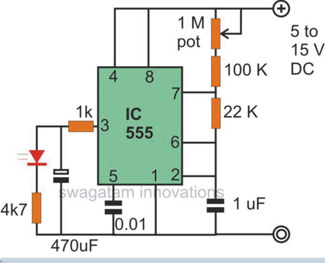
If you want to produce some strange illumination pattern over the LED discussed through the above circuits, them it can be simply done using just a couple of resistors at the output of the IC.
As can be seen in the figure, two resistors and a single resistor are connected at the output of the IC in a special way.
The network switches ON the LED sharply, but switches it OFF slowly, producing quite a creepy visual effect.
Alternate Flasher Circuit
This IC 555 LED circuit configuration is pretty straightforward, as we all know; two LEDs can be connected to the IC output for generating an alternate blinking pattern over the connected LEDs.
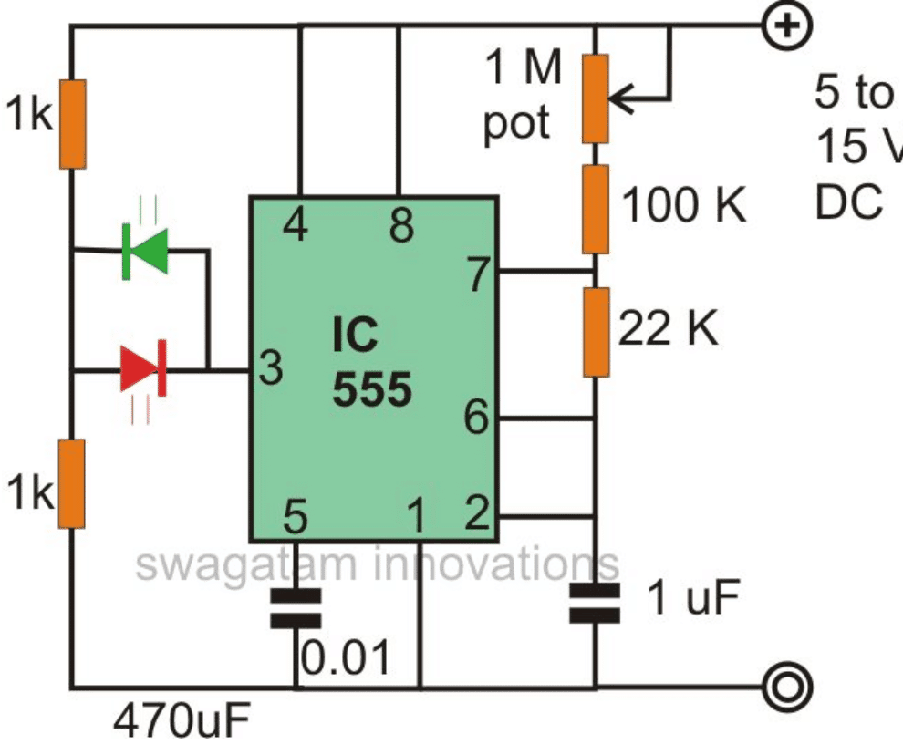
The above circuit can be further modified as shown below by complely disarranging the network with the shown type.
Here the LEDs though blink alternately, the intensity may fluctuate from dim to bright over the LEDs.
Light Fader Circuit Using IC 555
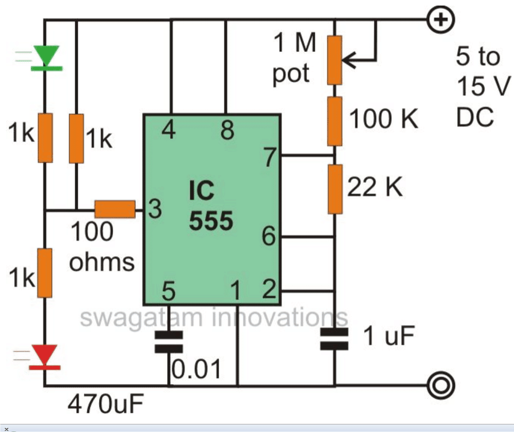
A very interesting light fading effect can be achieved by wiring up the IC 555 circuit as per the diagram shown below.
The circuit switches ON the LED very gradually and does the same while switching it OFF, that is instead of shutting it off abruptly, does it very slowly.
555 Strobe Light Circuit
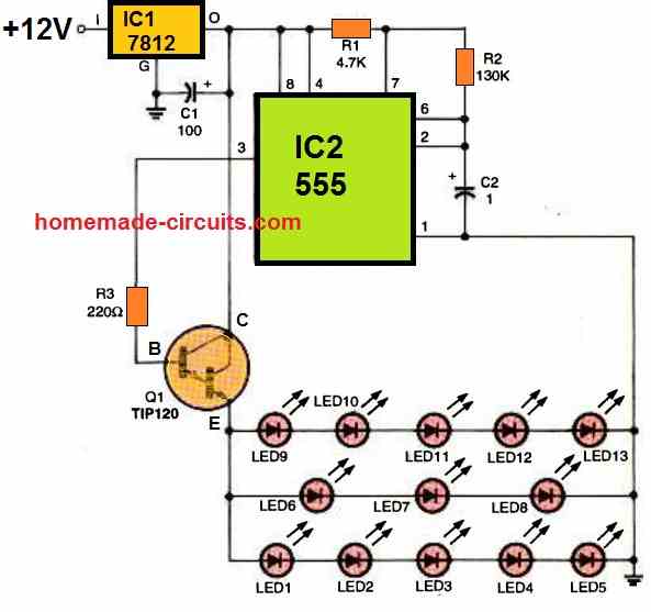
The next 555 LED circuit depicts a schematic design of the strobed-LED lighting system, which is based on a pair of commonly accessible integrated circuits (IC1, an LM7812 fixed 12 volt regulator, and IC2, a 555 oscillator/timer).
It is necessary to calculate the optimal duty cycle and frequency for the oscillator (IC2).
In other words, we're trying to perfect it when it comes to optimal frequency and duty cycle.
The circuit is set to run at a frequency of 3 Hz with a duty cycle of 50%. The operating frequency of this 555 strobe light circuit was determined with the help of a handy 1 uF capacitor C2 connected between pin6/2 and ground of the 555 timer/oscillator.
The 555 output (pin 3) is linked to the base of Q1, a TIP120 NPN Darlington transistor. The transistor, works like a switch and switches current to cause a strobing effect on the LED lighting module in response to the oscillator output (555 IC2).
Another Strobe Light Circuit using Two IC 555
The captivating strobe light circuit showcased below was generously shared by one of our dedicated blog readers, Mr. Vee.
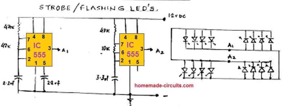
This design employs two IC 555 astable circuits, each operating at slightly distinct flash rates, resulting in a fascinating alternating strobe light effect across two sets of LEDs.
This striking LED strobing pattern not only captures attention but can also serve various purposes, including advertising displays, warning signal devices. It can be also used for automobile applications, for example as a car reverse alert lamp flasher, where the strobing LEDs warn the users regarding the reversing car.
Video Demonstration
555 Firefly Light Flash Simulator Circuit
It's not always the most elegant method to use a flashlight to attract fireflies for summertime evening entertainment with the kids.
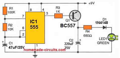
This straightforward circuit comes in handy by more accurately simulating a firefly flash in terms of color, attack and decay times, brightness, and frequency.
Our 555 LED firefly circuit is customizable to mimic the flashing attributes of any of the 125 varieties of fireflies prevalent across the country, seems to last eternally, avoids damp soil, will not really eat bugs (but uses electrons provided by a 9-volt battery).
R1, R2, and C1 control the timing of a 555 timer, which produces a 0.25 Hz, high duty cycle square wave.
A low duty-cycle signal is produced by inverting the output using the PNP transistor. The green LED's green luminous intensity slowly fades as the 220 uF capacitor discharges via the 680 ohm resistor (R4) and capacitor (C2).
An electric firefly that shines every four seconds is the final outcome. The green flash has distinct attack and decay characteristics and can last for around half a second.


Questions & Answers
hi sir,
sir i need your kind support regarding 12 volt led fade out and fade in circut, also required another circut for 12 volt trafic signal light plz
Hi Ghulam, for fade in fade out, you can try the following circuit:
https://www.homemade-circuits.com/wp-content/uploads/2020/05/fade-circuit.jpg
For traffic light, you can refer to the following article:
https://www.homemade-circuits.com/traffic-light-controller-circuit-signal-red-green-amber/
Hi Sir, I constricted a two alternate on/off led circuit with 555 IC which actually is driven by a bc 547 of a simple ldr circuit using bc547 and a preset. The emitter of the 547 is connected to the 4,8 pins of 555 so that the 4;8 pins get voltage only when the ldr circuit transistor is ON.The 555 is wired as typical PWM control circuit using two diodes and a preset connected to 6 and 2 pin of 555. The two leds are connected at the out pin 3 of 555 so as to get alternate flashing of leds. But sir how can I add a fading effect on the two leds without altering the other circuitry or is there any other simple circuit to get this. The circuit should work as day light becomes dim.
Hi Binoj, You can try adding a 220uF/25V capacitor parallel with each LED and check the response. Make sure to have a resistor in series with each LED.
Hello, I’m looking to make a circuit with 3 LEDs (red , blue and yellow) who will randomly blink from each other (not alternations, but random). With maybe a pot to adjust the speed of changes.
Any advice welcome
Cheers
Hi, you can try the “Random Light Effect Generator Circuit” from the above article.
Good day, my friend Swagatam!
I don’t like fast blinking LEDs. Therefore, I wanted to ask you about the circuit for 10-20 very slowly fading LEDs. What do you advise?
I have some 1206 SMD Leds. I want to adapt them for decorative lighting of mini Christmas trees or glue transparent balls with these diodes to make beautiful New Year’s toys.
Here is a toy I have already made: https://www.homemade-circuits.com/wp-content/uploads/2022/12/Christmas-toy.jpg
Respectfully,
Jorge
Thank you My friend Jorge,
The toy looks so cute and beautiful.
I think you can try building the following concept and see if it helps to fulfill your requirement or not:
https://www.homemade-circuits.com/alternate-onoff-led-fader-circuit/
The following 555 circuit might also work for the specified applications:
https://www.homemade-circuits.com/wp-content/uploads/2011/12/555-7-2.png
Thank your for these examples!
Have a question.
I’m interested in your opinion as an engineer. What can you say about this scheme?
Pls, see photo: https://ibb.co/gMH0sLg
I understand that there may be certain drawbacks in it, for example, I see that the chain of diodes D11-D20 must clearly be connected to the minus power supply.
Do you think this scheme works?
Respectfully,
Jorge
Hi Jorge,
The link is not opening in my computer browsers. Could to try uploading it to some other image hosting site?
OK!
New link: https://www.homemade-circuits.com/wp-content/uploads/2022/12/LED-fader.jpg
I checked the schematic, it looks like it will cause the LEDs to light up slowly when power is switched ON, but it will not flash the LEDs ON/OFF.
It has a current mirror circuit and a Darlington emitter follower, but there’s no feedback circuit anywhere to generate the ON/OFF flashing effect.
Hi, i am looking for a 555 led flasher circuit to be connected tyo a home alarm system with external leds that will indicate when the alarm system is disarmed/armed and when the alarm has been triggered.
When disarmed, led must flash at a specific rate. When armed, the leds must be constant on. When alarmed is triggered, the leds must flasher at a much faster rate.
Please advise which pin on the IC is connected to the alarm system for the trigger when alarm is activated when home is broken into.
Thanks
Hi, this will require a complex circuitry using more ICs or transistors, this cannot be achieved with a single 555 IC.
Can the 555 flasher circuits above have a string of leds added, that is stacking the led side of the circuit with other led circuits, so that a panel of leds could all be doing the same thing, or combining the above circuits so that some flash, others pulse, etc?
Yes that’s possible, you can put a couple of LEDs in parallel, or a couple of in series to the existing ones, and replicate the performance across the connected LEDs
I have a castle sculpture that has 6 acrylic spheres on the tip of 6 of the spires on the castles. I would like a 6 bulb slow blinking circuit designed (I don’t want them to all blink at the same time). I would like to remove the spheres, insert small led bulbs, the smaller the better, (recommendations?) then reset the spheres on the tip of the LED’s to simulate the spheres blinking. The sculpture reminds me of the castles you see in the movie Wizard of Oz.
Please let me know if you can help me out, and thank you for your time.
I think the following design might fulfill your requirement:
https://www.homemade-circuits.com/wp-content/uploads/2011/12/555-7-2.png
You can use 1 watt LED on each of the positions, and replace the 1k resistor with a 22 ohm 1 watt resistor.
You can build 6 of these units and use them inside the relevant spheres.
I am interested in making the fader circuit. Using the potentiometer to slow the fade rate. In your diagram, it looks like you substitute the potentiometer for the initial resistor from the positive pole. Is this correct? I am a novice so do potentiometer come in different values? Maybe you could send a revision to your diagram showing how to attach the potentiometer and any other resistors.
Thanks
Chuck Reed
The 1M pot is for adjusting the flashing rate, if you want to adjust the fading rate, you can add a 4k7 pot in series with the 1k shown at pin3 of the IC
What is 1M ? Which resistor or capacitor we use for it?
1M = 1 Meg Ohms (potentiometer)
sorry but the “Light Fader Circuit Using IC 555” doesn’t work at all.
In the video you can see all the circuits working….try changing the capacitor, or try finding why the current is not reaching the LEDs.
There is no video about the Light Fader Circuit Using IC 555.
Please see the attached video fully, the fading effect is included in the video.
Tryed the “Light Fader Circuit Using IC 555” one, but the output voltage from the capacitor on pin3 is only about 2.50V and I need at least 3.1V. What can I do?
what supply voltage did you use.
5V max. Please note that I need a very smooth effect or alternating “breathing”. I want to connect two 3.2V 150mA LED strings.
Please check the voltage without the LEDs, and directly across pin3 and ground. During the ON periods, the voltage should be almost 5V, if not then it could be the fault of the IC, because there are no external components that can affect the pin3 voltage
Without the capacitor (an electrolitic one) at pin3 the voltage is almost 5V. If I connect the leds directly at pin3 one string only turn on and off but without breathing effect. I’ve tryed to put two transistors at pin3 after the capacitor (one NPN and the other PNP) but the effect is horrible and one string doesn’t even turn off
Without the capacitor there won’t be any fading effect, I told to remove it only to confirm the pin3 voltage.
If 5V is available without the leds and the capacitor, then the IC is OK.
However, with the capacitor initially the LEDs will get full 5V, and then gradually the 5V will diminish as the capacitor charges, that’s how the fading effect is created.
with a 470uF capacitor the 3.3 V LED must light up initially and then gradually fade off
Thank you very much sir,
I want to make a police revolving light effect for large Christmas lights, what should I add to the 555 output for 12v and 300W led lights?
Thank you
Tirta, you can modify the design in the following manner
for 300 watt replace the TIP122 with mosfet IRF540.
Hi dear Swagatham
I assembled the 2nd circuit (Making a Police Revolving Light Effect). It is working perfectly as said in the explenation.
Following are the changes that I had made in the circuit.
1)Supply ….12VDC
2)LED…..Old type 5mm YELLOW LED.
3)Inplace of 1mfd, I used 10mfd.
4)I don’t had 0.01mfd at that time, so I used a 0.015mfd polyester capacitor.
5)I simply avoided 1M POT.
6)I just swapped the 22K and 100K.
(I will replace the old type YELLOW LED with a high brightness RED (for Police vehicle dom light effect) / WHITE LED (for LIGHT HOUSE effect), when it is available. Then only I will get the exact revolving light effect…..!!!!!)
Thank you Dear Anil for your valuable feedback, Appreciate it very much.
Ok sir thank u very much
Thank you very much sir, please one more question, is it increase in values, increase in flash rate or decrease in values increase in flash rate?
it is the opposite, you can easily experiment all these by practically testing it…
Thank u sir,
1. what is the function of 1M Pot?
2. In the link you referred me to, Which capacitor and resistor determine the flash rate?
The 1M pot and the 1uF capacitor values determine the flashing rate
Questions sir,
1. for 4th circuit you referred me to, can i add red LED to say 4 or 5 and connect them in series, and add the green also?
2. Does the two LEDs (red and green) swap their illumination? At which time interval?
yes you can do that if the supply is 12V.
yes they will swap at a rate decided by the capacitor and resistors values
please use the following design
https://www.homemade-circuits.com/wp-content/uploads/2011/12/555-5-2.png
Hello sir, i greet u. Am interested on this article, i need a circuit whereby i will connect 8 LEDs in series 4 red 4 green, the red LEDs will illuminate for 5 seconds as soon the time elapsed, it will shut off then the green LEDs will also illuminate at the same time interval alternating, which of the circuit you posted should i use?
Solomon, please try the 4rth design for your requirement…
So on the Light fader circuit I need 9pc LED do i just add them in array replacing the 2 led in your example using 5v input, or do i have to add 100 ohms resistor on each led I add?
9 may not work at 12V, you can add at the most 4 to 5 LEDs, high bright 3.3V rated 20mA type