The following article discusses a simple automatic micro UPS circuit which can be used with modems for acquiring uninterrupted power from a DC source, and battery during mains power failures. The circuit also incorporates an automatic over charge cut off, and a low battery indication feature. The circuit was requested by Mr. Kapil Goel.
Technical Specifications
Hi Swagatam, How are you, and was really happy to read your blog as I was scrolling through circuit sites for my requirement.If you can help me out for that, I have a requirement:
This is exactly what my requirement is: I have a 12volt operated device, it consumes approx 35 watts right now I power it up using a 12volt adapter, but when main power fails its get rebooted..
I wanted to use 12volt 2200mh Li-ion battery pack so that whenever there’s a power cut it will automatically shift to battery.
Also, the circuit should have over charge protection, and low battery indicator.
At last I am not asking this circuit for free, as I am ready to pay for it. Many thanks in advance
Regards, Kapil Goel
UPDATE: New Simplified Micro-UPS Circuit
No need to build the op-amp based complex circuits explained in the following article. You can simply build and the implement the below shown simple micro-UPS circuit for your modem UPS application:
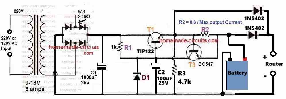
The zener diode D1 value must be selected such that the output voltage across R3 is slightly less than the maximum full-charge level of the battery. For example, if the maximum full charge level of the battery is 14.3V, then select the D1 value appropriately which generates around 14V across R3.
The R2 value can be calculated using the following formula:
R2 = 0.6/Battery charging current.
For lead acid battery, the suitable battery charging current can be around 10% of the battery Ah, and for Li-Ion battery this can be around 50% of the battery Ah.
Micro-UPS Circuit with Battery Over Charge Cut-off using Op-amp
The design was actually presented in one of my earlier posts also, however it does not include an automatic over charge cut off feature.The present design has similar functions, but has an added protection feature in the form of an automatic battery over charge cut off and also an under voltage indicator.
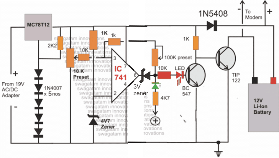
The proposed circuit diagram of an automatic micro UPS may be understood with the following points:
The input supply is acquired from any standard AC/DC adapter rated anywhere within 15 and 19V DC, current at anything above 1.5 amps.
The above supply is regulated via a 7812 IC whose ground pin is elevated to about 2.4V so that the output from the IC gets raised to about 14.4V rather than the normal 12V.
This is required because the attached 12V battery needs to be supplied with a slightly higher potential than its rated value.
How the IC 741 is Configured
The 741 IC stage is configured as a comparator.
Its pin#2 is clamped to a fixed reference voltage of 4.7V using a suitably rated zener diode.
Pin#3 is rigged as the sensing input if the IC via an adjustable preset.
The preset is adjusted such that the potential at pin#3 just exceeds the potential at pin#2 when the battery voltage crosses the 13.5V mark.
As long as the above situation is not sensed, the output of the IC at pin#6 sticks to it initial zero voltage level which in turn keeps the BC547 transistor switched OFF. With BC547 being switched OFF, the TIP122 gets a chance to conduct via the 1K resistor and charges the connected battery.
The battery terminals are directly connected with the modem which is being used for some application.
This allows the modem to remain powered via the external AC/DC adapter while the battery gets charged simultaneously.
The battery is allowed to charge freely until it reaches the over charge threshold when the output at pin#6 of the IC goes high, switching ON the connected BC547 transistor.
The above switching cuts off the base bias to the TIP122 transistor and stops the battery from getting further charged. This does not affect the modem as it continues to acquire power from the external power supply.
During mains failure, the supply from the external adapter gets inhibited, and the modem starts receiving back-up supply from the battery.
Since no relays are used the transition is within micro seconds which keeps the supply to the modem interrupted during power failures or even under heavy power fluctuations.
If the mains stays absent for long, and the battery reaches its over discharge threshold, the situation is immediately indicated with the green LED, which can be also replaced with a buzzer. The modem should be switched OFF then, to stop damage to the battery due to over discharge.
The adjustment of the 100K preset determines the low voltage threshold mark or the lower indication. level.
Once the green LED is lit, it will remain lit until the battery is fully charged, similarly once the red LED illuminates, it will stay illuminated until the green LED lights up or when the battery voltage level falls below the set lower threshold.
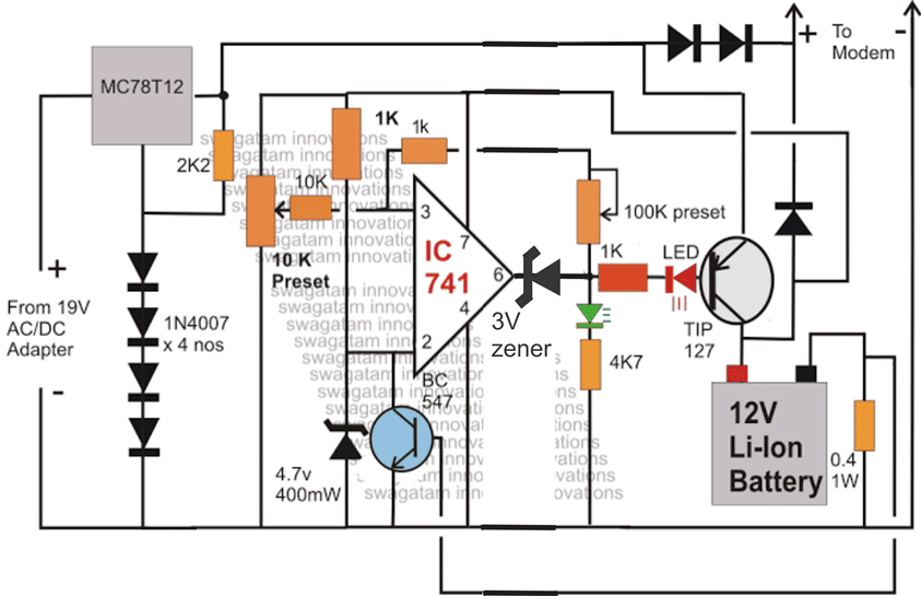
Using a PNP BJT for the above Charger Circuit
The above circuit can be also configured in the following manner, here the LED indications get reversed, meaning red LED shows low voltage while the green LED indicates high voltage threshold.
The following circuit also incorporates a current limiting facility which can be used for providing a current controlled charging to the connected battery.
FEEDBACK from Mr. Kapil
Hi Swagat,
Thanks for the circuit.. I really appreciated your swift and kind response..
I have couple of questions on the same.
1) What will be the max current it will support, my device requires atleast 5 amps 12 volts, will this be able to handle that.
2)As per the circuit, I can see, you have directly connected the modem to the battery, but if I am not wrong, this means that modem will keep on taking the power from battery, and battery will not get charged?
Please I clear out this confusion.
Also I am using a li-ion battery, which has a voltage of 12.6 volts on full charge and 11 when discharged.
Also my input volt is also 12volts, I cannot use a higher volt rated adapter.. will it be able to charge my battery at fullest.
Regards,
Kapil Goel
My Reply
Hi Kapil,
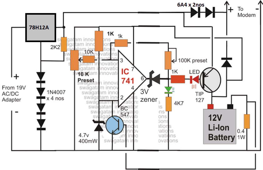
Presently the above shown circuit is rated at 3 amps maximum, so I may have to amend the design to suit your requirements, however the input voltage will need to be above 13V otherwise the battery will never get optimally charged.
The direct connection of the battery with the modem will not affect the battery charging as long as the input source power is active....both outputs will be simultaneously taken care of.Regards.
The modified 5 AMP micro UPS circuit design:


Questions & Answers
yes it's automatic. cell phone battery will not be suitable for this application.
i have only battery and solar unit.how can i get it charged and low battery cutoff…and also how to stop the over charging????
what are the ratings of battery and solar panel?? Please specify them.
best circuit i have tryd this its working well thanx dear……, can u tell me the function of 100k vr???? regards
thanks, it's for setting the under charge cur-of limit for the battery
Hi,
Very useful circuit, thanks for sharing it, I want to ask that What is the difference between 0.4 ohm resistance and 100 K Var? 0.4 ohm resistance determines battery charge current, But i dont understand what is main function 100 K variable resistance?
Regards,
Hi thanks, the 100k pot sets the low voltage restoration threshold for the battery…it decides when the charging needs to be restored for the battery
Hello Swagatam Majumder sir , please help me i want to adjust your two circuit https://www.homemade-circuits.com/2013/08/3v-45v-6v-9v-12v-24v-automatic-battery.html and https://www.homemade-circuits.com/2013/04/automatic-micro-ups-circuit.html so please can u send me or post a combined circuit.
Hello Shawon, how do you want both the circuits to be combined?
I want to use this automatic micro ups circuit but the cutoff overcharge,over discharge and battery charge level-indicator like https://www.homemade-circuits.com/2013/08/3v-45v-6v-9v-12v-24v-automatic-battery.html should included
auto cut off is already included in the above circuits, for indications you can integrate the following circuit with the battery:
https://www.homemade-circuits.com/2013/08/make-this-10-step-battery-voltage.html
dear swagatam desighn a circuit that would drive a cell phone camera, i have a vga camera
hello, can use battery 12 vlt 7 ah ? gel?
Dear, another query. I can use instead of a red LED indicator low loads a relay to make the outage charge the battery to avoid damage?. I contribute it as an idea and at the same time consultation. thank you!
Yes a 7ah gel battery can be used here.
I did not understand your second question.
asks is: if instead of using red to indicate low battery LED, use a relay to cut the supply battery.
the transistor will cut off the supply on battery full charge
bottom right that says 0.4 1w resistor is 400 ohms 1w?, thanks!
hi can u please tell me about any mini projects in which op amp ic 741 is used???
bottom right that says 0.4 1w resistor is 400 ohms 1w?, thanks!
it's 0.4 ohms
HI Swagatam
Do you have any circuit to get 12V (1.5 – 2A) from USB supply?
Hi Abu-Hafss,
you can use a 555 boost circuit for it, I have already published a few of those in this blog, and guess you have read them all
Hi,
my English is not so good. I have four questions to the last schema (5 Amps).
1. If I am correct, this circuit keeps battery in safe – it prevents battery from overcharging, when battery is fully charged, it cut off from power. And when battery voltage drops down under given threshold it starts charging. Am I right?
2. I see in your schema Li-Ion battery. Can I use for example Lead Acid battery 12V/1Ah?
3. Battery voltage should not drop under given threshold for avoiding damaging. This circuit does not cut off battery when it happens, right? RED led will lit instead, right? If I put to RED led some kind of relay or one or two MOSFETs to cut off battery, it could work?
4. Can you confirm me that RED led will lit only when battery voltage is low under safe limit and GREEN led will lit only when battery is fully charged?
Thank you!
Hi
1) yes that's right.
2)All types of rechargeable battery can be used here for the required actions.
3) yes that's correct
4) yes that's correct too!
hello Swagatam..
i have 2 questions please:
1. can i make this circuit without the charger part?? cuz i have an automated charger.. so i dont like it to be charger twice..
2. can i use an acid lead battery with 70 amp "car battery" instead of the one you recommneded..
thank you a lot
hello Ahmad, do you mean you want to replace the MC78T12 section with you charger output?? yes it can be done.
any battery can be used here as long as the voltage specification is 12V
hi again..
please i want to make a 12v charger from a laptop adatpter with 19v/3.5amp
how to regulate 19v to 14 or 13.5 to make it charge the battery??
and would it cut off if the battery is full ?? i mean how to make a simple overcharge protection circuit??
thank you a lot
You can use a LM338 variable voltage regulator circuit and use it for getting the required 13.5V from the 19V input.
after adjusting it to 13.5V you will need to operate the above circuit with this voltage for acquiring the automatic high/low cut-offs.
Sorry for the inconvenience
but what is the difference between LM338 and LM317?
bucause i tried to get 13.5 volt with LM317 but no success..
and please what resistor should i use with LM338?
and what resistor should i use with LM317??
thank u again
LM317 will allow a maximum of 1.5amps for the connected load.
LM338 will allow 5amps max, and LM196 10amps max.
the basic configuration will be the same for all the above ICs.
you can make the first circuit shown in the following post, applicable to all of these ICs:
https://www.homemade-circuits.com/2012/04/ic-lm338-application-circuits-explained.html
Use 10k pot instead of 5K for getting a wider range of control.
thank u again Swagatam
i used lm317 because i want the max 1.5amp and i got everything ok
i got 13.6 v but the ic get too hot.. is that normal?? of course i installed a heat sink but it still get hot and the volt is decreasing slowly.. should i install a fan ??
or should i use lm338 ??
thaaaaaaaaaaank you a lot
you are welcome Ahmed,
you may increase the heatsink dimensions, or as you said use LM338 which would run much cooler…
hi Swagatam..
1) i replaced the lm317 with lm338 and installed a biger heatsink with fan and it worked,, but the question is.. why do i have only 1.63 amp output?? since the laptop charger is 3.4amp.. why don't i have the complete 3.4amp when i charge a 12v battery?? in the other hand when i used lm317.. it gaves 2.0 amp 😐 !! how did that happen ??
2)can i get an overcharge protection circuit but simpler than the one above… for 12v battery and for 6v battery..
thanks again
Hi Ahmad,
How did you measure the current, in series with load or with battery, or by directly putting meter prods across the output?
A simpler circuit is shown here, you can try this one as well.
https://www.homemade-circuits.com/2011/12/self-regulating-lead-acid-battery.html
i measured in series with empty battery.. it started with 0.5amp and increased to 1.63 and never increased again..
and another questions.. since its a laptop charger.. does it have an overcharge protection feature already ?? or should i build a circuit because i modified the output to 14v ??
thanx
That's strange, the current consumption should be high when the battery is first connected and should gradually become less as it charges, at full full charge it should almost become zero amps…I think something may be not correct either with your circuit or the meter you are using.
The charger will never have any protection feature, but your laptop will certainly have a built-in over charger cut off included.
hi mr.Swagatam how can i use this circuit with 4v battery ???
Hi Ahmad, use 7806 for the input IC and don't use the diodes with its ground pin, connect the ground pin directly with the ground, rest everything remains as is.
set the preset for a 4.2V cut off
how can i control the charging current in circuit 2???
the current may be controlled by appropriately selecting the 0.4 ohm resistor value (in the last diagram)
Hey Mr. Swagatam,
If I want to charge a lead acid battery 1,2ah, I need to change the value of 0.4 ohm to 3 ohm resistor for 1/10h battery charge?
Hi Elber, yes that's right!
Hi Swagatam,
I would like to know if acid-lead battery can be used with this circuit, for example 2 pieces of 6v 4.5 ah batteries. My power requirement is 12v, 1ah for D-link 2750u adsl router+modem. Thanks.
Hi Roney, yes definitely lead acid batteries can be used with the above circuits.
Hi Swagatam,
I would like to know what is the variable resistances total value? You said (for left one) preset 10 K ohm, what is the total value of this one? I mean, is the total value is 50 K ohm and we set it to 10 K ohm?
Regards,
Hi Cem, the total value is 10K, it's a 10k preset or trimpot
Hi Swagatam
Is it normal that regulator gets hot during battery charging?
regards.
Hi Francisco, yes it's very much normal for any voltage regulator to become hot while driving any load
Thanks Swagatam.
Probably you Can help me. I am facing some issues to set the trimpots correctly. I am using a 7808 voltage regulator and a 6v/1a battery to be charged. How can I calculate the trimpots and zener values to adjust the correct voltages on pin3 and 2 from 741?
Regards.
Thank you for your attention.