In situations as critical as a COVID-19 pandemic, a doctor is the one personnel who is the most susceptible to getting infected by the virus from a patient.
Therefore, doctors are being continually offered and equipped with many advanced and high tech devices in an effort to guarantee maximum safety to their life and health.
The PPE kit as we know is the primary, first line of defense that the doctors get to safeguard them from a COVID-19 patient. However, despite of this doctors can get infected due to one basic reason which is their frequent close proximity with patients, while diagnosing.
The most basic diagnosing procedure that any doctor has to implement is the checking of the heart rate of a patient with a stethoscope.
And while using a stethoscope the doctor has to inevitably come at a precariously close distance to the patient's mouth and body.
This can definitely pose a high risk for the dictor especially if the patient is a COVID suspect.
However, science and technology is one field which is never out of ideas, and the above situation is no exception to it.
A bluetooth stethoscope can be one such device that can enable a doctor or any medical staff to check the heart beat of a patient from a safe distance using an ordinary mobile headset.
What you will Need
To make a bluetooth heart rate monitor circuit, you will need the following basic ingredients:
- A Bluetooth transmitter circuit with a 3.5 mm jack adapter
- A MIC amplifier circuit
- Suitable enclosure for the above units, which can be hooked up with a strap belt.
The Bluetooth transmitter can be purchased ready made from any online store. One standard example is sown below:
Working Concept
The following block diagram explains the main essential stages of the MIC amplifier.
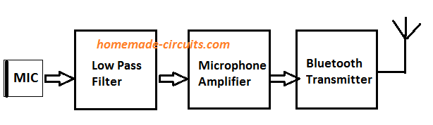
The working concept of the proposed wireless bluetooth stethoscope circuit is rather simple:
- The heart beat sound pulses hit the MIC, which converts them into equivalent electrical pulses.
- These electrical pulses are amplified by an integrated op amp amplifier stage to appropriate levels.
- The amplified signals are fed to a bluetooth transmitter input which converts them into wireless bluetooth signals.
- The transmitted bluetooth signals are captured by a tuned mobile phone which converts it back into audible signals.
- The converted bluetooth data through the mobile headphone is used by a concerned doctor for diagnosing the patients heart rate and the related ailments.
Heart beat Frequency and working
The sound of our heartbeat are in the form of semi-periodical waveforms which are generated due to the turbulent movement of blood when the heart beats.
Normally, a heartbeat sound of a healthy person is generated with two subsequent pulses, termed as the first heart sound (S1), and the second heart sound (S2) as revealed in the following figure:
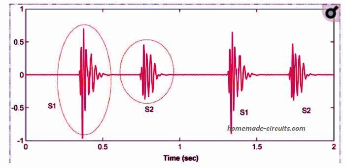
Image Courtesy: heartbeat waveform
Each set of these pulses last for about 100 ms, which is actually quite sufficient for any relevant medical analysis.
Also, because the frequency of the pulses are between 20 and 150 Hz, it becomes convenient to examine the waveform within the 1st and the 2nd music octaves.
This requires a low pass filter designed in accordance with the frequency specifications of the heart rate, as I have explained below:
Designing the Low Pass Filter
Often, a heart sound may be accompanied with various background noises generated from other body organs sounds. As a result, conditioning the data becomes an essential job to ensure that the audio transmission is efficiently processed.
The basic reason of including a low pass filter is to ensure that only the genuine heart beat frequency is amplified by the system, and the other unwanted frequencies are blocked.
Additionally, the heart sounds may contain several higher frequencies having bigger variations. For this reason, filtering and noise cancellation of unpredictable pulses becomes a crucial undertaking. The easiest way to achieve this through a low pass filter.
A low-pass filter designed with a fpass = 250 Hz and fstop = 400 Hz provides a good range for controlling the above explained scenario.
Since, we already have an active op amp based amplifier in the design, the low pass stage could be achieved with an ordinary RC passive filter as given below:
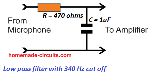
In the above low pass filter circuit any frequency above 350 hz will be severely attenuated.
The cut-off result could be adjusted or verified using the following formula;
fc= 1/(2πRC), where R will be in ohms and C will be in farads.
Designing the Crucial MIC Amplifier
The MIC amplifier design is crucial and must ensure that it amplifies only the low frequency heart rate, and blocks other higher frequency disturbances.
For the MIC, we use the popular electret MIC, which is the recommended device for all microphone based circuit applications.
For the amplifier, we use a standard IC LM386 based amplifier circuit.
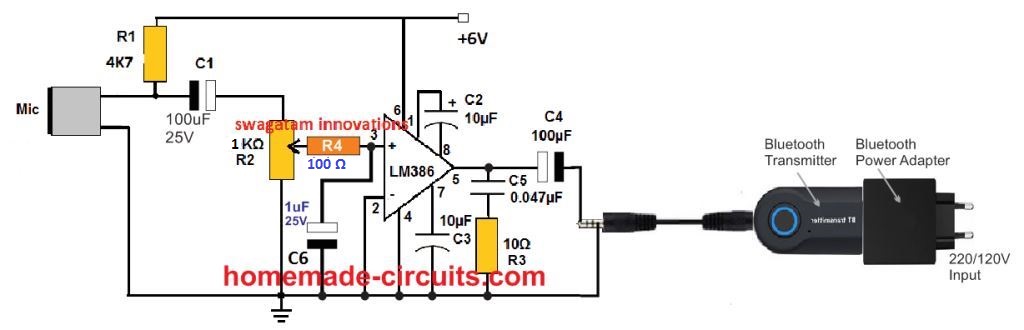
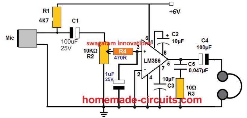
The entire circuit of the bluetooth stethoscope transmitter circuit is shown below:
Parts List
- Resistors 1/4 watt 5%
- 4k7 = 1
- 100 ohm = 1
- 10 ohm = 1
- preset 1k = 1
- Capacitors
- 100uF/25V electrolytic = 2
- 1uF/25V electrolytic = 1
- 10uF/25V electrolytic = 2
- 0.047uF/50V ceramic disc = 1
- IC LM386 = 1
- Electret MIC = 1
- Bluetooth transmitter with audio input pin and adapter as shown
How the Circuit Works
The bluetooth heartbeat sound transmitter works in the following manner:
Heart beat sounds hitting the electrte MIC are converted into tiny electrical signals, at the junction of R1, C1.
R1 works as the biasing resistor for the inner FET of the MIC.
C2 ensures that only the AC content of the MIC pulses are allowed to pass to the next stage, while the DC content is blocked.
The AC pulses equivalent to the heart beat sound is fed to the input of an LM386 amplifier circuit via a volume control pot R2, and the subsequent low pass filter using R4, C6.
The low pass filter ensures that only the true heartbeat frequencies get amplified by the LM386 circuit, and the remaining unwanted entries are suppressed.
The amplified output is generated across the C4 negative terminal and the ground line.
A Bluetooth transmitter can be seen integrated with the output of the LM386 amplifier stage for the intended wireless Bluetooth conversion of the amplified heartbeat signals.
How to Test the Bluetoooth Stethoscope Circuit
Since the Bluetooth transmitter module is a ready made tested unit, its working is assured.
Therefore, the only thing that needs to be tested and confirmed is the LM386 circuit.
This is done by checking the output of the amplifier through a pair of headphones, a shown below.
The MIC must be neatly clamped near the person's chest area where the heart beat sound is most prominent.
Now, as soon as the circuit is powered, the heart beat sound should be audible across the head phones.
If the sound has problems or is not clear, try optimizing the parameters until the sound is distinctly clear. This may be done by adjusting the volume control pot, and/or the the value of the capacitor C2. The supply voltage to the circuit could be also tweaked for the same.
Care must be taken that the MIC does not oscillate or rub against the body of the person to whom it is attached, which may otherwise create a huge amount unnecessary disturbance at the output, obscuring the actual heart beat sound.
Confirming the Results on a Mobile Phone
Once the headphone test is completed successfully, the headphone could be replaced with the Bluetooth transmitter.
Next, the Bluetooth transmitter will need to be paired with the receiver unit which can be a smart phone or any mobile phone.
Once paired, and powered, the signals from the amplifier will be captured by the Bluetooth unit and transmitted into the air for a nearby Bluetooth device for receving the data.
The paired mobile will now work like a remote wireless Bluetooth stethoscope enabling a Doctor or a medical professional to analyse the patients heartbeat without the need of a practical examination of the patient. This device ensures the medical personnel a 100% safety from a possible infection arsing from a patient who may be suffering from a contagious disease like COVID 19 or similar.
- Warning: This concept has not been tested practically, however, since the idea is very basic, the author believes that the circuit will work and produce the intended results with some minor tweaking.
- Also, this circuit cannot be used as a medical device for treating or diagnosing real patients, unless and until the circuit is tested and approved by an authorized laboratory.


Questions & Answers
hello , how to connect it to a phone ? and do you have a code for that ?
You will need to download a Bluetooth oscilloscope app in your mobile phone, then pair it with the Bluetooth transmitter and check the waveform. You can also purchase a Bluetooth oscilloscope separately and do the same procedures for receiving the Bluetooth signals from the transmitter and checking the waveform.
The above article only gives a general idea regarding how to convert the heart beats into Bluetooth signals so that it can received by any Bluetooth waveform processing device for the required inspections.
can we use this circuit to listen baby heart beat which is still inside mother womb.
It will only detect sounds that are audible to human ears, otherwise not
hello , may i know how to connect the bluetooth transmitter to the amplifier ?
hello again , sorry for bothering but if you can put all the materials required to build this prototype here it would be great . thanks
Hello, I have updated the parts list under the diagram.
It is shown in the second last diagram.
I HAVE BEEN LOOKING DIAGRIAM FOR 7 MONTH COULD NOT FIND IT ,IS IT PSSEBLE I CAN PUT PIC ON THE COMENNTS PLEASE THANK AND HOW, REGARDS RUI DE PINHO
You can try the concept which is explained in the above article.
Can I use LM386 audio amplifier module instead of this circuit for Bluetooth stethoscope?
Yes you can!
Do we just connect the microphone to the module or will a separate circuit be required for that ?
You will have to use an electret MIC with the LM386 circuit
How Electret Microphones Work – Full Tutorial and Diagram
Thanks. Do you think this circuit will work. Am planning to make one to check chest congestion.
According to my understanding and knowledge the circuit should work as explained in the article.
I ask you help.
I am trying to develop ventilator and other equipment for Africa, I am a non profit. I want to incorporate some technology . I need help. In this case I would like to narrow the frequency range so as to eliminate spurious signals .
on a wider issue. If you can support me with advice on my ideas I will be very grateful. This covid pandemic is brutal. I need help. But I do not have money
Hi, I do not have much information regarding ventilator electronics, so it will be difficult for me to suggest you an appropriate solution for your query.
This is really informative. At least electronic engineers has a role to play in this critical situation.
Thank a lot .
Thank you very much! appreciate your valuable feedback.