MPPT stands for maximum power point tracker, which is an electronic system designed for optimizing the varying power output from a solar panel module such that the connected battery exploits the maximum available power from the solar panel.
Introduction
NOTE: The discussed MPPT circuits in this post do not employ the conventional control methods like "Perturb and observe", "Incremental conductance, "Current sweep", "Constant voltage"......etc etc...Rather here we concentrate and try implementing a couple of basic things:
- To make sure that the input "wattage" from the solar panel is always equal to the output "wattage" reaching the load.
- The "knee voltage" is never disturbed by the load and the panel's MPPT zone is efficiently maintained.
What's Knee Voltage and Current of a Panel:
Put simply, the knee voltage is the "open circuit voltage" level of the panel, while the knee current is the "short circuit current" measure of the panel at any given instant.
If the above two are maintained as far as possible, the load could be assumed to be getting the MPPT power throughout its operation.
Before we Delve into the Proposed Designs, let's first get acquainted with some of the basic facts regarding solar battery charging
We know that the output from a solar panel is directly proportional to the degree of the incident sunlight, and also the ambient temperature. When the sun rays are perpendicular to the solar panel, it generates the maximum amount of voltage, and deteriorates as the angle shifts away from 90 degrees The atmospheric temperature around the panel also affects the efficiency of the panel, which falls with increase in the temperature.
Therefore we may conclude that when the sun rays are near to 90 degrees over the panel and when the temperature is around 30 degrees, the efficiency of the panel is toward maximum, the rate decreases as the above two parameters drift away from their rated values.
The above voltage is generally used for charging a battery, a lead acid battery, which in turn is used for operating an inverter. However just as the solar panel has its own operating criteria, the battery too is no less and offers some strict conditions for getting optimally charged.
The conditions are, the battery must be charged at relatively higher current initially which must be gradually decreased to almost zero when the battery attains a voltage 15% higher than its normal rating.
Assuming a fully discharged 12V battery, with a voltage anywhere around 11.5V, may be charged at around C/2 rate initially (C=AH of the battery), this will start filling the battery relatively quickly and will pull its voltage to may be around 13V within a couple of hours.
At this point the current should be automatically reduced to say C/5 rate, this will again help to keep the fast charging pace without damaging the battery and raise its voltage to around 13.5V within the next 1 hour.
Following the above steps, now the current may be further reduced to C/10 rate which makes sure the charging rate and the pace does not slow down.
Finally when the battery voltage reaches around 14.3V, the process may be reduced to a C/50 rate which almost stops the charging process yet restricts the charge from falling to lower levels.
The entire process charges a deep discharged battery within a span of 6 hours without affecting the life of the battery.
An MPPT is employed exactly for ensuring that the above procedure is extracted optimally from a particular solar panel.
A solar panel may be unable to provide high current outputs but it definitely is able to provide with higher voltages.
The trick would be to convert the higher voltage levels to higher current levels through appropriate optimization of the solar panel output.
Now since the conversions of a higher voltage to higher current and vice versa can be implemented only through buck boost converters, an innovative method (although a bit bulky) would be to use a variable inductor circuit wherein the inductor would have many switchable taps, these taps may be toggled by a switching circuit in response to the varying sunlight so that the output to the load always remains constant regardless of the sun sunshine.
The concept may be understood by referring to the following diagram:
Circuit Diagram
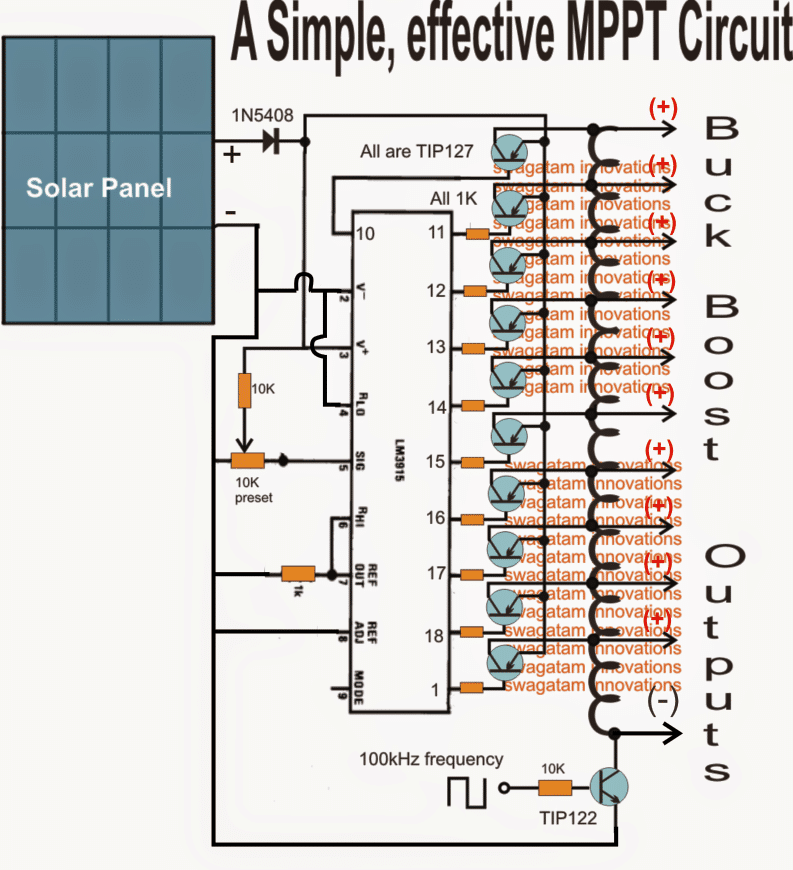
Using LM3915 as the Main Processor IC
The main processor in the above diagram is the IC LM3915 which switches its output pinout sequentially from the top to the bottom in response to the diminishing sun light
These outputs can be seen configured with switching power transistors which are in turn connected with the various taps of a ferrite single long inductor coil.
The lower most end of the inductor can be seen attached with a NPN power transistor which is switched at around 100kHz frequency from an externally configured oscillator circuit.
The power transistors connected with the outputs of the IC switch in response to the sequencing IC outputs, connecting the appropriate taps of the inductor with the panel voltage and the 100kHz frequency.
This inductor turns are appropriately calculated such that its various taps become compatible with the panel voltage as these are switched by the IC output driver stages.
Thus the proceedings make sure that while the sun intensity and the voltage drops, it's appropriately linked with the relevant tap of the inductor maintaining almost a constant voltage across all the given taps, as per their calculated ratings.
So I have explained the functioning with the help of the following scenario:
Suppose the coil is selected to be compatible with a 30V solar panel, therefore at peak sunshine let's assume that the upper most power transistor is switched ON by the IC which subjects the entire coil to oscillate, this allows the entire 30V to be available across the extreme ends of the coil.
Now suppose the sunlight drops by 3V and reduces its output to 27V, this is quickly sensed by the IC such that the first transistor from the top now switches OFF and the second transistor in the sequence switches ON.
The above action selects the second tap (27V tap) of the inductor from top executing a matching inductor tap to voltage response making sure that the coil oscillates optimally with the reduced voltage...similarly, now as the sunlight voltage drops further the respective transistors "shake hands" with the relevant inductor taps ensuring a perfect matching and efficient switching of the inductor, corresponding to the available solar voltages.
Due to the above matched response between the solar panel and the switching buck/boost inductor...the tap voltages over the relevant points can be assumed to maintain a constant voltage through out the day regardless of the sunlight situation....
For example suppose if the inductor is designed to produce 30V at the topmost tap followed by 27V, 24V, 21V, 18V, 15V, 12V, 9V, 6V, 3V, 0V across the subsequent taps, then all these voltages could be assumed to be constant over these taps regardless of the sunlight levels.
Also please remember that these voltage can be altered as per user specs for achieving higher or lower voltages than the panel voltage.
The above circuit can also be configured in the flyback topoogy as shown below:
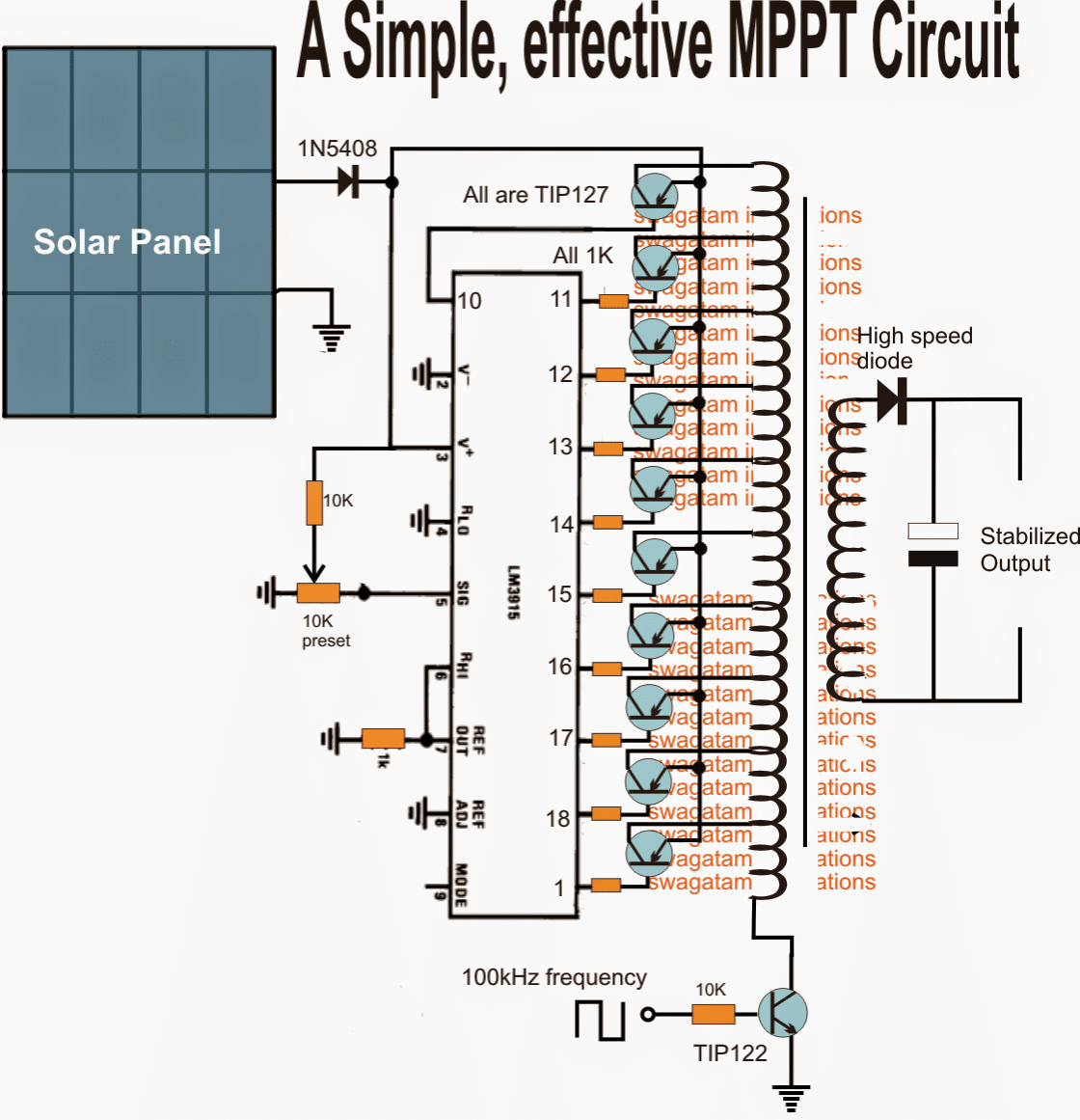
In both the above configurations, the output is supposed to remain constant and stable in terms of voltage and wattage regardless of the solar output.
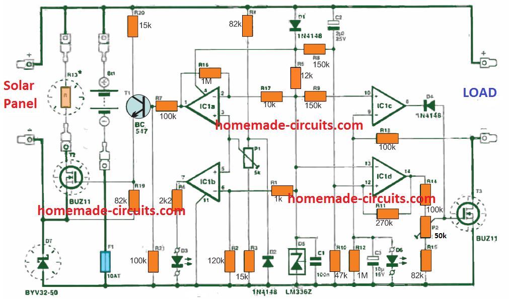
Using I/V Tracking Method
The following circuit concept ensures that the MPPT level of the panel is never disturbed drastically by the load.
The circuit tracks the MPPT "knee" level of the panel and makes sure that the load is not allowed to consume anything more which might cause a dropping in this knee level of the panel.
I have explained how this can can done using a simple single opamp I/V tracking circuit.
Please note that the designs which are without a buck converter will never be able to optimize the excess voltage into equivalent current for the load, and might fail in this regard, which is considered as the crucial feature of any MPPT design.
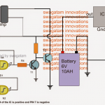
A very simple yet effective MPPT type device can be made by employing a LM338 IC and an opamps.
In this concept which is designed by me, the op amp is configured in such a way that it keeps recording the instantaneous MPP data of the panel and compares it with the instantaneous load consumption. If it finds the load consumption exceeding this stored data, it cuts off the load...
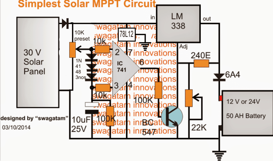
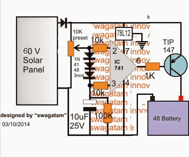
The IC 741 stage is the solar tracker section and forms the heart of the entire design.
The solar panel voltage is fed to the inverting pin2 of the IC, while the the same is applied to the non-inverting pin3 with a drop of around 2 V using three 1N4148 diodes in series.
The above situation consistently keeps the pin3 of the IC a shade lower than pin2 ensuring a zero voltage across the output pin6 of the IC.
However in an event of an inefficient overload, such as a mismatched battery or a high current battery, the solar panel voltage tends to get pulled down by the load. When this happens pin2 voltage also begins dropping, however due to the presence of the 10uF capacitor at pin3, its potential stays solid and does not respond to the above drop.
The situation instantly forces pin3 to go high than pin2, which in turn toggles pin6 high, switching ON the BJT BC547.
BC547 now immediately disables LM338 cutting off the voltage to the battery, the cycle keeps switching at a rapid pace depending upon the IC's rated speed.
The above operations make sure that the solar panel voltage never drops or gets pulled down by the load, maintaining an MPPT like condition throughout.
Since a linear IC LM338 is used, the circuit could be yet again a bit inefficient....the remedy is to replace the LM338 stage with a buck converter...that would make the design extremely versatile and comparable to a true MPPT.
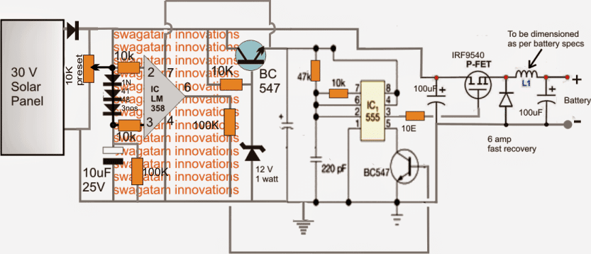
Below shown is an MPPT circuit using a buck converter topology, now the design makes a lot of sense and looks much closer to a true MPPT
48V MPPT Circuit
The above simple MPPT circuits can be also modified for implementing high voltage battery charging, such as the following 48V battery MPPT charger circuit.
The ideas are all exclusively developed by me.
Discussion & Solutions
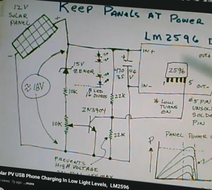
Good morning, it’s been a long time I spoke to you last, sir. i hope everything is doing great. I built a solar charge controller(steping doewn higher DC voltage to 5v DC) using lm2596 and some other components to see input and output voltage, my solar panel is three panel(9v, 9v, 6v) panell connected in series, under open circuit the voltage is 30v. now after the project has been completed I noticed the heatsink i attached to lm2596 is very hot, I checked online and I was due to large voltage ratio(30v : 5v), so I want to implement crude mppt and maybe even uvlo, I found a circuit on YouTube so I want you to check it sir, change all components to work for my solar spec.
this is the image:
https://drive.google.com/file/d/1A5M-chQPYavZD20b4SkqPXvOXlvHCvFy/view?usp=drivesdk
Hi Jerry, the LM2596 is a buck converter, not a linear regulator, so it should not heat up too much even if the voltage differential is large. However it may heat up if the load current draw is large.
What is your load current?
By the way you can try the following version if your current requirement is bigger:
https://www.homemade-circuits.com/0-to-50-v-adjustable-switching-power-supply-circuit-using-ic-lm2576/
The linear regulator at the input side is simply not required, because then your linear regulator will start dissipating heat, and the whole purpose of using the buck converter would be defeated…
pls pardon me, I meant a buck converter that use of lm2596, also I intend to implement a crude mppt by adding this circuit I found on YouTube, pls sir help check it out will it work? my load current is just under 2A.
Yes, it should work to control and maintain the MPP level of the solar panel…
Dear Swagatam
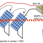
I hope you are doing fine. I have seen several MPPT circuits from your site however in local market I have seen another one which is going strong as far as its specs are concerned.
The setup is where 7 Solar plates are connected in Series and returning 48 Volt + 7 = 336 Volts total. This voltage is given as Input to a so called MPPT local device (a locally made Desi version) and its output is 230V 7 to 10 kva. The AC and fridges are connected at its output.
My understanding is since higher DC voltage is connected and used so copper in transformer (if any) should be minimal and so the ratio of primary and secondary and power conversion losses are lowest as well but I am not sure what circuit is actually used. Can you suggest as what might be used or can create one.
Regards
Thank you Abdus, for your interesting question.
The copper that you are suggesting is the copper winding I guess.
The copper winding should be as per the calculations and the operating frequency, which must be precisely implemented.
To minimize losses the copper wire can be in the form of multiple thin wire strands instead of a single thick wire, which minimizes skin effect and increase efficiency. The core of the transformer is mostly ferrite so the core losses are already minimal.
Commercial MPPT circuits can be quite complex and sophisticated, which might be beyond the reach of my expertise, so designing them could be difficult for me.
Dear Swagatam
Thanks for your quick response.
No I am not expecting some very sophisticated device but I love your home grown solutions so just a little understanding for something quick trick may work for me. You can direct me to some already made schematics or a group of schematics so I can start experimenting with it. Moreover in starting version it may not be a very powerful device but rather a proof of concept version for 1KVA or similar and I can later experiment with it for more power. Its for my personal endeavor so need to be a commercial project.
Local commercially sold unit cannot be said to be professional one either for instance there are No charging batteries etc. Local community is using it till 4PM with said load and turns off AC after that and after 5PM turns off fridges as well but fans etc. are working till 6PM and after that whole system is turned off. This turnoff of loads as discussed above is done manually.
Still if it is not viable as a personal project then its fine. I shall still search for it and if found out then I shall also share it with you.
Thanks for your co-operation and responses.
Regards
Thank you Abdus,

If you want to experiment with an MPPT concept then I would recommend you the second design from the above article.
It is the most viable looking MPPT design because it exploits the basic voltage/current conversion principle of a transformer, which makes sense.
You can initially experiment using a small iron core transformer for a small 100 watt load, just to check if the concept really works or not.
Although the results might not be too accurate, still it should be good enough.
For an iron core transformer the switching frequency to the TIP122 must not exceed 60 Hz.
I have a 560ah 24V LiFePo4 battery. I have a BMS that monitors each cell and will disconnect the panel from the battery if any one cell exceeds 3.5V. There is no charge controller. I want to try your circuit to see if it will do a better job of matching to the panel’s optimum power output. The battery is typically at 27V and the panel’s optimum is 33V, so I am probably not getting as much power as possible.
Note, I don’t need the MPPT to taper the current to achieve max charge, because the Sun does the tapering for free each day. I just need the MPPT to deliver as much power as the panel will provide, and of course shut off when the BMS opens a circuit.
Am I correct to conclude that the “Simplest Solar MPPT Circuit” will do the job?
Is the version with the buck converter only more efficient? In that circuit what should L1 be?
Thanks for this excellent article!
Thank you for visiting this site! The opamp based simple MPPT circuit is designed to cut off the load whenever it tries to exceed the MPP specifications of the panel, preventing the solar panel from dropping below the MPP level. The cut off and restoration process is switched continuously ensuring that the panel output always remains within the MPP zone. You can try it and check the response.
The buck converter is presented only as a concept, the actual part values are not known. You can try integrating some other buck converter circuit with known part values.
Oh hang on, this is not going to do the T part of MPPT. It won’t track, right? I will only maintain the panel at a set voltage. MPP specifications includes temperature, which means that this circuit will match the MPP only if the temperature matched, right?
Have you designed a circuit that will hunt for the max power?
Yes that’s correct, the op amp circuit will only make sure that the load does not destroy the knee voltage of the panel at any instant.
For hunting max power the first two circuits can be used. But even these circuits simulate MPPT, they are not real MPPT. The first two circuits will continuously track the panel voltage and try to match it with the transformer winding voltage levels to ensure that the output load is able to extract the maximum power from the panel.
We have a crank/pedal powered device that outputs 300 watts (50 volts). We intend to recharge two 12 volt 65 AH batteries by channeling the output through an MPPT. As the generator is pedal powered, power generation will not be constant but will vary with the pedalling, which is why we thought of the MPPT.
We think that the output from the MPPT should be sent to each battery separately for charging.
Can you help us with a design for a circuit for this purpose, or is a readily available MPPT capable of handling the outpower appropriate for the job.
I don’t think MPPT would be required in your case. If your pedaling speed reduces the MPPT will not be able to increase the current from the system.
Instead, you can try a buck converter circuit for converting your 50V to 14 V, that will be very efficient.
My thinking was:
If the generator output is 300 watts, and charging a 12v 65AH battery requires only 78 watts (12 x 6.5, ie 10% though I am told we can charge up to 20% of 65, ie 13), the excess power would be unutilised. If I connect two batteries in parallel to the MPPT I can charge two similar batteries at the same time.
A buck converter will reduce the voltage but will it enable charging of two batteries? We think we will be able to keep the voltage from going below 50V
An MPPT also uses a buck converter which makes sure that the excess power is not wasted. 10% rate is the recommended rate for a lead acid battery which ensures an increased life for the battery. If you use a buck converter then the 50 – 12 = 38V would be converted into excess current so that you can even charge 3 batteries in parallel at 6.5 amp rate.
I can’t figure out how an MPPT could be used with a generator.
please how can I make a good buck converter for 60v 10amps to 24v battery system
You can try the following design:
https://www.homemade-circuits.com/lm317-variable-switch-mode-power-supply/
Replace the PNP transistor with TIP36.
Make sure the IC is LM317-HV, the HV version can handle upto 60V input.
I didn’t know that a buck converter would convert excess voltage into amps, I thought only MPPTs did that.
So I can connect 3 batteries of equal voltage to the output of the buck converter to charge them?
Yes, that’s the main purpose of a buck converter. If your buck converter is highly efficient then 3 batteries may be possible otherwise only 2.5 batteries.
Thanks for the reply. I have not yet connected the MPPT. I spoke to a manufacturer. The idea is to convert the generator output to DC using diodes, then from the diodes to the input of the MPPT.
I have no electrical or electronics background. Just an idea I am pursuing.
I checked online and found that yes MPPT works with generators, but buck converter is a much easier and cheaper option. However you can try a readymade MPPT circuit with your generator it will work.
Hi, thanks for the inspiration.
Regarding the circuit for the following,
How to achieve the final setting for the 10k preset?
Do you have guidelines for sizing the choke L1?
After revising the details I realize that the 10K preset should not be there. The inverting input of the op amp should be directly connected with the solar panel.
However, for this to work, the op amp rating must be higher than the solar voltage. For example any op amp with 32V rating could be selected and a solar panel lower than 32V could be used with the op amp circuit.
How hard is it to dsign a 12 kW DC-DC converter to convert power from an Electric Vehicle battery (325-400VDC) to 138.6VDC to run my APC Symmetra UPS on DC?
Fantastic article! Thank you for contributing!
How can I contact you to discuss a custom MPPT? Cannot post the details of the project publicly now.
I prefer discussing through comments only, sorry about it.
Hi,I will build this circuit any modifications?
Thank you for your projects..
Hi, I’m trying to build an all in one inverter+charger with 48V solar input with MPPT and battery and grid bidirectional converters so I can charge the batteries and once they’re full redirect power to grid. be able to get power from the grid and the batteries
Something like a Eg4 3000 ehv-48
I would like to know if you have any circuits for this
Hi, that appears to be quite complex and big, I do not have this design with me at this moment.
I have 36volt solar (4.4amps) and I want to charge a 12v battery which will be connected to an inverter (150 watt), which of the circuit can I use to achieve an mppt output from the panel.
You can try the second design, or you can also try the following design:
https://www.homemade-circuits.com/0-to-50-v-adjustable-switching-power-supply-circuit-using-ic-lm2576/
Hi:
I am trying to build a DC MPPT controller of a sort. Probably better to call it a MPPT limiter. I want to power an electric oil radiator type heater (no fans, manual thermostat) directly from a small solar array (3 x 500w panels in series). Panels are rated at 545W, OCV 49.6V, MPPV 41.8V, SCI 13.92A, MPPI 13.04A. This would give max power output at about 125 vdc and about 13A. I need to keep the panels as close as possible to MPPT at full output, of course if the solar output is lower it would just run at the available voltage and current. I don’t want to use a voltage boost converter, I just want to limit the maximum output of the solar array to the MPPT. Load resistance would be around 10 ohms for a 1500w heater. Maximum efficiency without inverters or boost converters is the goal.
The 48v circuit is interesting, but I don’t see how it maintains a constant charge voltage for the battery or even senses battery voltage at all. Could I simply substitute an SSR for the TIP147 to handle the appropriate load current and just have a bang bang controller?
Hi,
I agree with you…the last circuit which is a 48V battery MPPT type charger does not have a voltage regulator. The circuit only detects an over current and cuts off the supply. It makes sure the panel voltage is never allowed to drop below its maximum rated output except a margin of around 2%. I will try to upgrade the last circuit with a voltage regulator soon.
However for a crude load such as a heater coil the voltage regulation may not be crucial, and only the MPPT regulator as suggested in the 48V circuit should be enough.
Sir:
The circuit as it stands does not monitor current, only panel voltage, so it can’t directly “detect an over current”, other than indirectly by detecting the panel voltage dropping.
I assume you set the pot so the circuit trips at or just below the MPP voltage of the panel(s). You didn’t address my question about the SSR. The TIP147 does not have the current or voltage capacity to handle a 120VDC solar array at 13A, but a 25A or 40A SSR with an DC rating of 220v would easily handle this load. What kind of frequency does this oscillate at when switching? It looks like it would sort of output a variable frequency PWM while it is regulating, the SSR would need to be able to operate at this frequency. I assume the 100K/10uF time constant would affect this?
Would this rapid switching of load current on the solar panels generate a lot of EMI/RFI? Or cause some detrimental effect on the system?
Silicon Alchemist, the 48V circuit will cut off the supply to the load when the panel voltage starts dropping, which can only happen when the load draws high amount of current. So indirectly the circuit will monitor an excess current consumption by the load. The pot actually can be used to determine the output voltage but ideally it should be used to fine-tune the MPP cut off.
You can replace the transistor with an SSR which can be used to handle higher voltages easily.
The output oscillation will be a kind of variable frequency PWM and will depend on the load current consumption and the panel voltage level. There could be some EMI generated just as we have in zener diodes.
If the load is a sensitive CMOS device or an audio amplifier then this frequency might have some effect on it.
Hi Swagatam,
Can we use the last 48v circuit without a buck on a resistive load like a water heater without a battery? I do PV direct water heating at the moment using a 48vdc element and was wondering if this design can improve the efficiency and maintain my input PV voltage.
Regards
Musa
Hi Musa,
yes, you can use the last circuit for resistive loads effectively. The circuit will cut off whenever the load tries to consume excess power beyond the capacity of the solar panel and thus will maintain optimal power output from the panel
Hi Swagatam,
Tried it with my setup and realized my current is a bit more than what the circuit can handle. Some smoke came out and there was a little bit of heat. I need to change some components to accommodate my 43V and 20A open from my panels.
Please advise on which components to modify to accommodate my input (43V and 20A).
Regards
Musa
Hi Musa,
The 7812 IC can handle a maximum of 35V, it will burn at anything above 35V. I am not sure if your 741 IC is also burned or not?
You can replace the 7812 with the following transistorized regulator circuit and check if this helps. The zener diode value can be a 12V 1 watt zener. Also the transistor TIP147 can handle a max current of 2 or 3amps without heating up.
GOOD job bross , I can see that knowledge is there for u
If I may ask you can you be supplying me some of these designs in which I we just be housing them here.
I,m from Nigeria here ?
No problem Akintunde, let me know what exactly you want, I will try to help…
I have the following setup: 204Vmp(max) x 25A PV + 100.8V(max) x 30A 24S Li-Po + 5kW(98V) BLDC.
I cannot find an MPPT for the above. Would it be possible to make my own? Any schematics? Thanks.
(I’m a Mech.Engr.& programmer, not Electrical Engr.)
Sorry, presently I do not have an MPPT circuit for the mentioned BLDC motor
If i connect 160v dc to MPPT it will convert 12v with out lose ampere
yes if the inductor transformer is selected correctly