The post presents a simple transformerless 1.5V DC power supply circuit which can be used for powering wall clocks directly from mains, and also keep a stand by back-up cell fully charged for enabling an uninterrupted operation of the clock even during mains failures. The idea was requested by Cheekin
Warning: This circuit is not isolated from mains AC and therefore is extremely dangerous to touch in powered condition, users are advised to apply extreme caution while handling it or testing in an uncovered position.
The Design
The figure shows a simple 1.5V transformerless power supply circuit for wall clocks that would never allow the clock to stop due to a depleted battery as it would keep running from the mains and also be reinforced with a battery power to ensure that the clock does not stop even during a mains failure.
The below shown design is a simple transformerless power supply using a 0.33uF capacitor as the input current limiter component in order to restrict the mains current to a modest 16mA.
Circuit Diagram
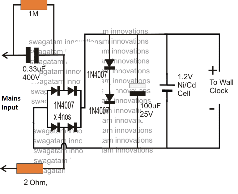
Hopefully this current will keep the clock ticking satisfactorily and also keep the attached Ni/Cd cell trickle charged and ready for an emergency back up.
If the 0.33uF does not provide adequate current for the operations, you can increase it to a higher value which just satisfies the application needs.
The indicated 1.5V transformeless power supply for a wall clock is able to develop the required 1.5V DC at the output with the aid of the two forward biased 1N4007 rectifier diodes across the (+), (-) terminals of the supply, which effectively shunts the massive 330V mains (@ 20mA) to a nominal 1.5V DC.
The inclusion of the two shunting diodes also ensures an entirely surge free supply for the clock and the charging cell, and therefore the design is relieved from other conventional forms of surge protection devices.
How it Works
Briefly the 1.5V transformerless supply circuit for clocks can be explained as follows
The mains input current is dropped to a lower 20mA by the 0.33uF/400V capacitor.
The bridge rectifier converts the above low current input to a low current DC variant, which is further acted upon by the two 1N4007 diodes which shunts the DC to a fixed 1.5V approximately.
This 1.5V / 20 mA DC is finally used for operating the desired wall clock, and also for charging a connected 1.2V Ni/Cd cell which reverts its DC each time mains fails, ensuring a failproof uninterrupted supply for the clock so that the unit never stops due to any adverse reasons.



Questions & Answers
Thank you for the circuit given. May I ask can the same circuit be used in a 3 volts wall clock (2pcs. of 1.5v battery).
yes that's possible by adding two more diodes in series with the existing 2 diodes…..or simply replace them with a single 3V 1 watt zener diode.
Thank you for the reply
What happens if I took out ni/cd cell. Actually I need clock which run on ac supply and stop when ac mains fail so that I can find out for how much time supply was inturpted.
you can do it if the backup facility is not required.
Hi I wish to confirm what you mean by 'yes that's possible by adding two more diodes in series with the existing 2 diodes…..or simply replace them with a single 3V 1 watt zener diode.' is it completely removed the 2 1N4007 doides as shown in the diagram and replace it with the zener diode only. Thanks.
yes if 3V zener is used then no diodes will be required at the indicated position….but make sure that the zener polarity is opposite to the 1N4007 polarity
'but make sure that the zener polarity is opposite to the 1N4007 polarity' do you mean the diode connection in the original circuit, I have to reverse the zener diode opposite i.e the + terminal of the zener diode to the + voltage line. Thanks.
the lead of the zener which has a black band will go to the positive rail and the lead which has no band will go to the negative line.
Thank you very much for the prompt reply.
Hi, I don't have 0.33uf/400v cap. Instead I have a stock of 0.47uf/400v. so can I use 0.47uf/400v instead of 0.33uf/400v? Will it make any difference in the output?
Hi, you can use 0.47uF instead of 0.33uF according to me, that won't cause any harm since NiCd cells are rated to handle much more current than 20mA for charging….
May I know the wattage rating of the two resistors (1M and 2 ohm) which are connected to AC main?
both are 1/4 watt rated
Sir can you please let me know why the circuit as mentioned gave me some problem. After a few days in used the time seem to run faster a few seconds. Thanks.
cheekin, did you confirm the voltage of the supply with a DMM? make sure it is not above 1.5V…
you can also try reducing the 0.33uF to 0.22uF/400V and see if that helps to improve the results.
Thanks for the reply. I will try and get the 0.22uF/400VAC capacitor, my place also hard to find capacitor with this type of voltage. The battery appear warm. By the way do you know any electronics components seller which can deliver Malaysia.
you can try contacting any reputed online spare part store for getting the part sent at your destination….
Thanks.
What's the purpose of the 2 Ohm resistor?
to limit or restrict switch ON power surge current…
After much finding everywhere the nearest capacitor according to them is Cap 470nF 10% 310VAC. which they say is same as 470uF 400VAC but with 310vac. Can this type of capacitor suitable for use in this project. Thanks
470nF = 0.47uF
you can use two of them series to make 0.22uF
or use two 0.1uF/400V in parallel.
Thanks Swagatam Majumdar for the prompt reply. Can I used 470F 310VAC. capacitor instead of 400VAC. I was wondering in some country sourcing for components is a problem. If we used a AC to DC power adapter with a range of 1.5V to 12V.type what way could we modify it to work properly as without modifying I have a problem the clock does not function properly.
470nF/310V will also do.
if you want to use an adapter, you may try it by attaching the following circuit in between the output and the clock
https://www.homemade-circuits.com/2012/08/simplest-dc-cell-phone-charger-circuit.html
replace 220 ohm with 10K, and 9V zener with two 1N4007 in series having cathode towards the ground
the TIP 122 could be replaced with a BC547
correction: the 9V zener must be replaced with three 1N4007 series diodes.
Thanks Swagatam Majumdar may I ask that charger circuit is having 12 volt input, if I used the 12 volt output from my adapter will it be OK for the clock of the 1.5v and 3v.Will be much appreciate if you can let me know what setup for 1.5v and 3v will be to use from the charger circuit.
thanks cheekin, the transistor regulator circuit which I refereed in the link will drop your adapter's 12V to 1.5V after the suggested modifications are done, so it will be fine.
Thanks again for the prompt reply. I just wish to ask at the 12V range setting in the adapter is it I can used it for the 3V used even without any further modification.
sorry I am unable to understand your question correctly…a 12V supply cannot be used for a 3V load in anyway
Thanks for the reply. What I mean is that 'the transistor regulator circuit' if I switch the voltage range from the adapter i.e. say I switch to the range of 3V or any voltage range from the AC to DC adapter it can be used with that circuit.
yes, regardless of the input fluctuations, the output will be regulated to a constant 1.5V using the above linked transistor emitter follower design
Thanks again for the information.
How to modify such that instead of ac 12v-24v dc power supply is given?
if you want to use an adapter, you may try it by attaching the following circuit in between the adapter output and the clock
https://www.homemade-circuits.com/2012/08/simplest-dc-cell-phone-charger-circuit.html
replace 220 ohm with 10K, and 9V zener with two 1N4007 in series having cathode towards the ground
Can you please design a simple touch on/off circuit? Function will be one touched power on and then touched again power off the device.Power supply will be 3 to 9v.Thanks Abu Saeed.
you can try the following circuit
https://www.homemade-circuits.com/2016/07/simple-touch-sensor-switch-circuit.html
It is not 3 to 9v operated circuit also can u please make it more simple?
it cannot be simpler than this.
One more question for you to solve for me. The circuit which you provided in 'simplest-dc-cell-phone-charger-circuit' is for 1.5V. Can you give me the circuit for 3V. My adapter output is 1 to 12V with 500ma. Thanks.
you can get it simply by changing the shown zener diode with a 3.6V zener diode
Thanks for your prompt reply. May I ask is the earlier modification as you mentioned using 3 diodes in series, is it for dropping the voltage to 1.5V. My adapter maximum current is 500ma. as stated in the label how much current is it charging the 2 battery using the 3.6V zener diode. I do have 3V zener diode can it be used for it.
yes they are for setting up a 1.5V at the transistor emitter.
the current will be 500mA at the emitter side.
3V zener will not do, but you can add a 1N4007 in series to make a 3.6V equivalent making sure that the polities for the two diodes are opposite with 1N4007 having its cathode towards ground
Thanks for your reply. Do you mean using the 3V Zener plus adding 1 1N14007 diode in series with the zener diode.
yes 3V zener plus 1N4007 in series, as shown below
base—–I<—–>|——-GND
I tried and got this result using the same components (except the zener diode is 3V) in the circuit of 'simplest-dc-cell-phone-charger-circuit'. The voltage in the output is 2V. without load 11V, and with the 10K resistor and the 3V Zener diode in series with 1N14007 I got 1V reading (zener 3V cathode black ring to the base of transistor the other end to 1N14007 anode the cathode white ring to the minus rail. Is there something wrong with component connection or it is normal to get this result. Thanks.
with 3V zener diode the output will be around 2V, that's OK connect a 10K resistor across emitter and ground, this will keep the 2V constant…with 3V+1N4007 the voltage should increase to around 2.7V…verify the base voltage, it will be always around 0.6V more than the voltage at the emitter of the transistor.
Thanks for you speedy reply. I will tried it out as soon as I am home. One last thing I hope you can help me so I could test and see which will be best for me. The original circuit of the transformerless 1.5V Power supply which you have given is OK for the 1 battery used. Can you tell me the components need to change for a 3V battery (2pcs. 1.5V battery.
thanks, for getting 3V you just have to use 4 diodes instead of the shown two diodes in the diagram, just add two more 1n4007 in series with the existing 2 diodes.