The post presents a simple transformerless 1.5V DC power supply circuit which can be used for powering wall clocks directly from mains, and also keep a stand by back-up cell fully charged for enabling an uninterrupted operation of the clock even during mains failures. The idea was requested by Cheekin
Warning: This circuit is not isolated from mains AC and therefore is extremely dangerous to touch in powered condition, users are advised to apply extreme caution while handling it or testing in an uncovered position.
The Design
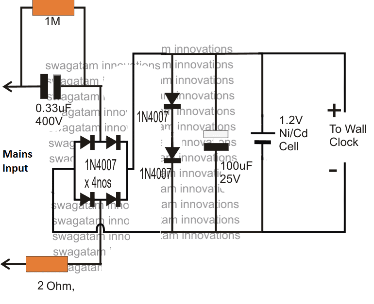
The figure shows a simple 1.5V transformerless power supply circuit for wall clocks that would never allow the clock to stop due to a depleted battery as it would keep running from the mains and also be reinforced with a battery power to ensure that the clock does not stop even during a mains failure.
The below shown design is a simple transformerless power supply using a 0.33uF capacitor as the input current limiter component in order to restrict the mains current to a modest 16mA.
Circuit Diagram
Hopefully this current will keep the clock ticking satisfactorily and also keep the attached Ni/Cd cell trickle charged and ready for an emergency back up.
If the 0.33uF does not provide adequate current for the operations, you can increase it to a higher value which just satisfies the application needs.
The indicated 1.5V transformeless power supply for a wall clock is able to develop the required 1.5V DC at the output with the aid of the two forward biased 1N4007 rectifier diodes across the (+), (-) terminals of the supply, which effectively shunts the massive 330V mains (@ 20mA) to a nominal 1.5V DC.
The inclusion of the two shunting diodes also ensures an entirely surge free supply for the clock and the charging cell, and therefore the design is relieved from other conventional forms of surge protection devices.
How it Works
Briefly the 1.5V transformerless supply circuit for clocks can be explained as follows
The mains input current is dropped to a lower 20mA by the 0.33uF/400V capacitor.
The bridge rectifier converts the above low current input to a low current DC variant, which is further acted upon by the two 1N4007 diodes which shunts the DC to a fixed 1.5V approximately.
This 1.5V / 20 mA DC is finally used for operating the desired wall clock, and also for charging a connected 1.2V Ni/Cd cell which reverts its DC each time mains fails, ensuring a failproof uninterrupted supply for the clock so that the unit never stops due to any adverse reasons.



Questions & Answers
It is difficult to expect anything good from using this circuit. It can cause the battery to overcharge and leak. The output voltage will be more than 1.2. If you use more IN 4007, you can get a voltage output of 1.2-1.4.
The full charge voltage of a 1.2 Nicd is around 1.5V….and also the current here is very low at 20mA. So don’t worry about overcharging.
The only concern is the non-isolated AC 220V floating across the whole battery area…so it is better to go for an SMPS
Hi Swagatam
how can I get pcb for 1.2 volt ni-cd battery for wall clock
Hi Haider, Sorry, It is not available readymade, you will have to contact a professional PCB designer for getting the PCB ready for you.
Hello Again Swagatam,
I hope you are doing well.
I just tried the final 1.2v circuit you sent earlier, and it doesn’t work as expected. The LED is lit okay, but the battery doesn’t charge, and the output is pretty high.
AC input is 220v – 230v
The voltage for the battery is 1.3v DC.
The voltage for the output is 2.3v DC.
Which is entirely wrong! It should be 1.5V or 1.6V for the battery and 1.2V for the output load.
Here is the final circuit I just made:
final-circuit-not-working-as-expected
Thank you Waleed,
You are saying the following circuit is wrong:
I am sure you have understood the technical aspects of the design, so I am interested to know how the output to the load can be 2.3V?
And how the voltage to the battery can be 1.3V?
Let me explain you how it works, for your understanding.
You can see the bottom 3 diodes in series, together they clamp the output voltage to 0.6 * 3 = 1.8V. The series diode near the switch deducts 0.6V again, making the output voltage to the load 1.8 – 0.6 = 1.2 V.
Since the battery is connected before the above diode, it gets the full 1.8V, which is OK, because the 10 ohm diode limits the current to the battery and restricts it to the required safe limit.
By the way how did you measure the voltages?
You must measure the voltage without the actual load and the battery, in the following manner:
Replace the battery with a 1k resistor and replace the load also with a 1k resistor, and now measure the respective voltages across these 1k resistors.
There may be some differences in the above explained voltage levels… because the 1N4148 may not drop the exact 0.6V across them.
The link you provided is not opening in my computer, please upload it some other image hosting site, I will check it out.
Hi Swagatam,
Thanks for the quick reply.
First, I tested without connecting the SPDT button to check the output voltage.
As you said, I double-checked and tested before connecting the battery without a load connection.
The battery’s voltage is 1.3v, and the load is 2.3v even after connecting the battery, but not the load.
Here are the hosted images:
Final Circuit:
https://drive.google.com/file/d/1eIlkEUWOSQXNEuIo21mf5t8uhH1Y6XFM/view?usp=sharing
With the battery:
https://drive.google.com/file/d/16T3Umn0FN_hwy6FYKnp4xQ36yYKGNJUH/view?usp=sharing
Without the battery:
https://drive.google.com/file/d/1TnkBNK2xR1_4je-6FDbARO2wUjuMuk0P/view?usp=sharing
Please check if I connected something wrong.
I appreciate any help you can provide.
Hi Waleed,
You circuit connections are correct.
Now please replace the battery points with a 1k resistor and check the voltage across this resistor and let me know.
Remember, the output voltage will ultimately depend on the individual diode’s forward voltage drop specifications, which is beyond our control.
Hi Swagatam,
I have connected 1k resistor and the voltage between it is only 1v DC but when turn the motor on the voltage drop to 0.9v or less.
I also tried to remove the led and the same output still occur 😔
Thank you Waleed,
As I said earlier, the final voltage will depend on the diode forward drop specifications. 1V instead of 1.2V is OK, because it is just 0.2V less, it is impossible to get exact 1.2V using diodes only.
If your trimmer working without issues then it is fine. The 0.9V drop also looks fine to me.
If the trimmer is not working good, then you can try increasing the input capacitor value to 1.5uF/400V, or add a 474/400V (0.47uF/400V) cap to the existing 1uF/400V.
Hi,
Maybe calculations are a thing, and real-life testing is another thing.
I said the battery’s charging voltage now is 1v or less not for the load, and you said it takes 8 hours to charge!! I know it takes that long, well, but the charging voltage should be at least 1.5v, so now the battery does not trigger the charge action.
Get my point?
I know the charging voltage must be 1.5V, that’s why i have tapped the voltage after series 3 diodes. Each diode drops 0.6 to 0.7V, so adding them gets over 1.5V.
You must first check whether the 3 series diodes are generating the voltage above 1.5V or not.
Did you check by connecting a 1k first?
Yes, I checked before and after connecting the 1k resistor, and it generates from 1v – 700mv – 400mv. Can you please re-check the required components and the connection once again? Is it possible to apply it yourself? I know you don’t have enough time.
I have explained you the function of the diodes, so please check the voltage across the 3 series diodes, and then across each of those 3 diodes. Do this with the 1k connected and without any battery or motor connected.
This will tell you why your circuit is generating 1V only.
By the way the voltage should not fluctuate between 1V, 0.7V. 0.4 V, otherwise it means something’s not right with your components.
The circuit diagram is correct.
I completed the circuit by connecting the 1.2v battery and the DC motor, but the battery was still not charging, and the motor stopped after the battery died. Ok, I’ll connect the 1k resistor and tell you the voltage.
Here is another image of the completed circuit:
https://drive.google.com/file/d/1GU3YsGjSm7ufsTMRqYtDY9eggwhAbWy4/view?usp=sharing
The battery will take 7 to 10 hours to charge and during this time the motor should not be used with the battery.