An ultrasonic water level controller is a device which can detect water levels in a tank without a physical contact and send the data to a distant LED indicator in a wireless GSM mode.
In this post I will show how to construct a ultrasonic based solar powered wireless water level indicator using Arduino in which the Arduinos would be transmitting and receiving at 2.4 GHz wireless frequency. We will be detecting the water level in the tank using ultrasonics instead of traditional electrode method.
Overview
Water level indicator is a must have gadget, if you own a house or even living in a rented house. A water level indicator shows one important data for your house which is as important as your energy meter’s reading, that is, how much water is left? So that we can keep track of water consumption and we don’t need to climb upstairs to access the water tank to check how much water left and no more sudden halt of water from faucet.
We are living at 2018 (at the time of writing of this article) or later, we can communicate to anywhere in the world instantly, we launched an electric race car to space, we launched satellites and rovers to mars, we even able land human beings on moon, still no proper commercial product for detecting how much water left in our water tanks?
We can find water level indicators are made by 5th grade students for science fair at school. How such simple projects didn’t make into our everyday life? The answer is water tank level indicators are not simple projects that a 5th grader can make one for our home. There are many practical considerations before we design one.
• Nobody wants to drill a hole on water tank’s body for electrodes which might leak water later on.
• Nobody wants to run 230 / 120 VAC wire near water tank.
• Nobody wants to replace batteries every month.
• Nobody wants to run additional long wires hanging on a room for water level indication as it is not pre-planned while building the house.
• Nobody wants to use the water which is mixed with metal corrosion of the electrode.
• Nobody wants to remove the water level indicator setup while cleaning the tank (inside).
Some of the reasons mentioned above may look silly but, you will find less satisfactory with commercially available products with these cons. That’s why penetration of these products are very less among the average households*.
*On Indian market.
After considering these key points, we have designed a practical water level indicator which should remove the cons mentioned.
Our design:
• It uses ultrasonic sensor to measure the water level so no corrosion problem.
• Wireless indication of water level real time at 2.4 GHz.
• Good wireless signal strength, enough for 2 story high buildings.
• Solar powered no more AC mains or replacing battery.
• Tank full / overflow alarm while filling the tank.
Let’s investigate the circuit details:
Transmitter:
The wireless transmitter circuit which is placed on the tank will send water level data every 5 seconds 24/7. The transmitter consists of Arduino nano, ultrasonic sensor HC-SR04, nRF24L01 module which will connect the transmitter and receiver wirelessly at 2.4 GHz.
A Solar panel of 9 V to 12 V with current output of 300mA will power the transmitter circuit. A battery management circuit board will charge the Li-ion battery, so that we can monitor the water level even when there is no sunlight.
Let us explore how to place the ultrasonic sensor at water tank:
Please note that you have to use your creativity to mound the circuit and protect from rain and direct sunlight.
Cut a small hole above the tank’s lid for placing the Ultrasonic sensor and seal it with some kind of adhesive you can find.
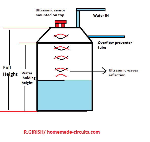
Now measure the full height of the tank from bottom to lid, write it down in meters. Now measure the height of water holding capacity of tank as shown in the above image and write in down in meters.
You need to enter these two values in the code.
Schematic diagram of Transmitter:
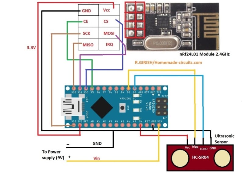
NOTE: nRF24L01 uses 3.3V as Vcc do not connect to 5V output of Arduino.
Power supply for transmitter:
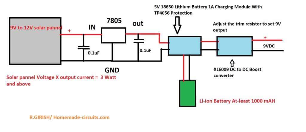
Make sure that your solar panel’s output power i.e. output (volt x current) is greater than 3 watts. The solar panel should be 9V to 12V.
12V and 300mA panel is recommended which you can find easily on market. Battery should be around 3.7V 1000 mAh.
5V 18650 Li-ion charging module:
The following image shows a standard 18650 charger circuit
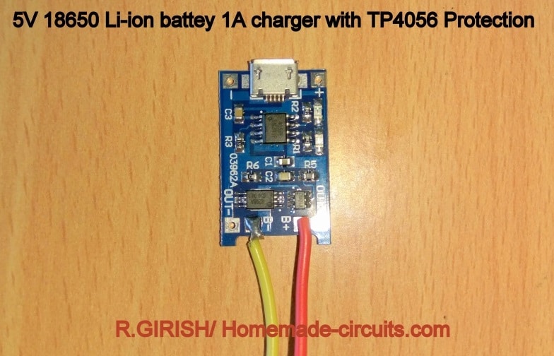
The input can be USB (not used) or external 5V from LM7805 IC. Make sure that you get the correct module as shown above, it should have TP4056 protection, which has low battery cut-off and short circuit protection.
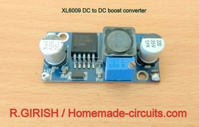
The output of this should to be fed to XL6009’s input which will boost to higher voltage, using a small screw driver output of XL6009 should be adjusted to 9V for Arduino.
Illustration of XL6009 DC to DC boost converter:
That concludes the transmitter’s hardware.
Code for Transmitter:
// ----------- Program Developed by Homemade-circuits.com ----------- //

#include <RF24.h>
#include <SPI.h>

// Create RF24 object using CE = 9, CSN = 10
RF24 radio(9, 10);

// RF address (must match receiver address)
const byte address[6] = "00001";

// Ultrasonic sensor pins
const int trigger = 3;
const int echo = 2;

// Messages to be transmitted
const char text_0[] = "STOP";
const char text_1[] = "FULL";
const char text_2[] = "3/4";
const char text_3[] = "HALF";
const char text_4[] = "LOW";

// Water level reference values (in meters)
float full = 0;
float three_fourth = 0;
float half = 0;
float quarter = 0;

// Ultrasonic timing and distance variables
long Time;
float distanceCM = 0;
float resultCM = 0;
float resultM = 0;

// Calculated water level variables
float actual_distance = 0;
float compensation_distance = 0;

// ------- CHANGE THIS -------//
// Total water holding depth (measured water column)
float water_hold_capacity = 1.0;   // Enter in meters

// Total physical tank height (sensor to tank bottom)
float full_height = 1.3;           // Enter in meters
// -------------------------- //

void setup()
{
  // Initialize serial monitor
  Serial.begin(9600);

  // Configure ultrasonic sensor pins
  pinMode(trigger, OUTPUT);
  pinMode(echo, INPUT);
  digitalWrite(trigger, LOW);

  // Initialize NRF24L01 module
  radio.begin();
  radio.openWritingPipe(address);
  radio.setChannel(100);
  radio.setDataRate(RF24_250KBPS);
  radio.setPALevel(RF24_PA_MAX);
  radio.stopListening();   // Set as transmitter

  // Calculate water level thresholds
  full = water_hold_capacity;
  three_fourth = water_hold_capacity * 0.75;
  half = water_hold_capacity * 0.50;
  quarter = water_hold_capacity * 0.25;
}

void loop()
{
  // Delay between measurements
  delay(5000);

  // Trigger ultrasonic pulse
  digitalWrite(trigger, HIGH);
  delayMicroseconds(10);
  digitalWrite(trigger, LOW);

  // Measure echo pulse width
  Time = pulseIn(echo, HIGH);

  // Convert time to distance (speed of sound = 0.034 cm/us)
  distanceCM = Time * 0.034;
  resultCM = distanceCM / 2;
  resultM = resultCM / 100;

  // Display raw measured distance
  Serial.print("Normal Distance: ");
  Serial.print(resultM);
  Serial.println(" M");

  // Calculate distance offset between sensor height and water depth
  compensation_distance = full_height - water_hold_capacity;

  // Convert measured distance into actual water level
  actual_distance = resultM - compensation_distance;
  actual_distance = water_hold_capacity - actual_distance;

  // Prevent negative water level values
  if (actual_distance < 0)
  {
    Serial.print("Water Level:");
    Serial.println(" 0.00 M (UP)");
    actual_distance = 0;
  }
  else
  {
    Serial.print("Water Level: ");
    Serial.print(actual_distance);
    Serial.println(" M (UP)");
  }

  Serial.println("============================");

  // Transmit water level status
  if (actual_distance >= full)
  {
    radio.write(&text_0, sizeof(text_0));   // Tank overflow / stop motor
  }

  if (actual_distance > three_fourth && actual_distance <= full)
  {
    radio.write(&text_1, sizeof(text_1));   // FULL
  }

  if (actual_distance > half && actual_distance <= three_fourth)
  {
    radio.write(&text_2, sizeof(text_2));   // 3/4
  }

  if (actual_distance > quarter && actual_distance <= half)
  {
    radio.write(&text_3, sizeof(text_3));   // HALF
  }

  if (actual_distance <= quarter)
  {
    radio.write(&text_4, sizeof(text_4));   // LOW
  }
}

// ----------- Program Developed by Homemade-circuits.com ----------- //
Change the following values in the code which you measured:
// ------- CHANGE THIS -------//

float water_hold_capacity = 1.0; // Enter in Meters.

float full_height = 1.3; // Enter in Meters.

// ---------- -------------- //
That concludes the transmitter.
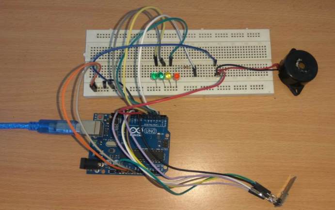
The Receiver:
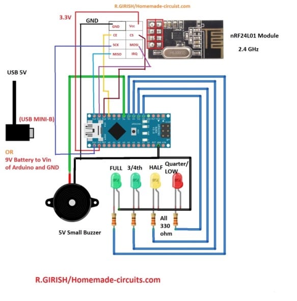
The receiver can show 5 levels. Alarm, when the tank reached absolute maximum water holding capacity while filling tank. 100 to 75 % - All four LEDs will glow, 75 to 50 % three LEDs will glow, 50 to 25 % two LEDs will glow, 25% and less one LED will glow.
The receiver can be powered from 9V battery or from smartphone charger to USB mini-B cable.
Code for Receiver:
// ----------- Program Developed by Homemade-circuits.com ----------- //

#include <SPI.h>          // SPI library for nRF24L01 communication
#include <RF24.h>         // RF24 library

// CE pin = 9, CSN pin = 10 (as per existing circuit)
RF24 radio(9, 10);

// Loop counter used for buzzer alarm
int i = 0;

// RF address (must match transmitter)
const byte address[6] = "00001";

// Output pin definitions (DO NOT CHANGE – tied to circuit)
const int buzzer = 6;
const int LED_full = 5;
const int LED_three_fourth = 4;
const int LED_half = 3;
const int LED_quarter = 2;

// Buffer to store received RF data
char text[32] = "";   // Max payload supported by nRF24L01

void setup()
{
  // Configure output pins
  pinMode(buzzer, OUTPUT);
  pinMode(LED_full, OUTPUT);
  pinMode(LED_three_fourth, OUTPUT);
  pinMode(LED_half, OUTPUT);
  pinMode(LED_quarter, OUTPUT);

  // Power-on indication: short buzzer beep
  digitalWrite(buzzer, HIGH);
  delay(300);
  digitalWrite(buzzer, LOW);

  // LED startup sequence (visual check)
  digitalWrite(LED_full, HIGH);
  delay(300);
  digitalWrite(LED_three_fourth, HIGH);
  delay(300);
  digitalWrite(LED_half, HIGH);
  delay(300);
  digitalWrite(LED_quarter, HIGH);
  delay(300);

  // Turn all LEDs OFF one by one
  digitalWrite(LED_full, LOW);
  delay(300);
  digitalWrite(LED_three_fourth, LOW);
  delay(300);
  digitalWrite(LED_half, LOW);
  delay(300);
  digitalWrite(LED_quarter, LOW);

  // Serial monitor for debugging
  Serial.begin(9600);

  // Initialize RF module
  radio.begin();
  radio.openReadingPipe(0, address);   // Set receiver address
  radio.setChannel(100);               // RF channel (must match transmitter)
  radio.setDataRate(RF24_250KBPS);     // Low data rate = better range
  radio.setPALevel(RF24_PA_MAX);       // Maximum power
  radio.startListening();              // Set module to RX mode
}

void loop()
{
  // Check if any RF data is available
  if (radio.available())
  {
    // Read received message into buffer
    radio.read(&text, sizeof(text));

    // Print received message on Serial Monitor
    Serial.println(text);

    // ---------- STOP command ----------
    // Turns ON all LEDs and activates alarm buzzer
    if (text[0] == 'S' && text[1] == 'T' && text[2] == 'O' && text[3] == 'P')
    {
      digitalWrite(LED_full, HIGH);
      digitalWrite(LED_three_fourth, HIGH);
      digitalWrite(LED_half, HIGH);
      digitalWrite(LED_quarter, HIGH);

      // Continuous buzzer alarm
      for (i = 0; i < 50; i++)
      {
        digitalWrite(buzzer, HIGH);
        delay(50);
        digitalWrite(buzzer, LOW);
        delay(50);
      }
    }

    // ---------- FULL level ----------
    // All LEDs ON
    if (text[0] == 'F' && text[1] == 'U' && text[2] == 'L' && text[3] == 'L')
    {
      digitalWrite(LED_full, HIGH);
      digitalWrite(LED_three_fourth, HIGH);
      digitalWrite(LED_half, HIGH);
      digitalWrite(LED_quarter, HIGH);
    }

    // ---------- 3/4 level ----------
    // Full LED OFF, remaining LEDs ON
    if (text[0] == '3' && text[1] == '/' && text[2] == '4')
    {
      digitalWrite(LED_full, LOW);
      digitalWrite(LED_three_fourth, HIGH);
      digitalWrite(LED_half, HIGH);
      digitalWrite(LED_quarter, HIGH);
    }

    // ---------- HALF level ----------
    // Half and quarter LEDs ON
    if (text[0] == 'H' && text[1] == 'A' && text[2] == 'L' && text[3] == 'F')
    {
      digitalWrite(LED_full, LOW);
      digitalWrite(LED_three_fourth, LOW);
      digitalWrite(LED_half, HIGH);
      digitalWrite(LED_quarter, HIGH);
    }

    // ---------- LOW level ----------
    // Only quarter LED ON
    if (text[0] == 'L' && text[1] == 'O' && text[2] == 'W')
    {
      digitalWrite(LED_full, LOW);
      digitalWrite(LED_three_fourth, LOW);
      digitalWrite(LED_half, LOW);
      digitalWrite(LED_quarter, HIGH);
    }
  }
}
// ----------- Program Developed by Homemade-circuits.com ----------- //
That concludes the receiver.
NOTE: if no LEDs are glowing, which means the receiver can’t get signal from transmitter. You should wait 5 seconds to receive the signal from transmitter after turning on the receiver circuit.
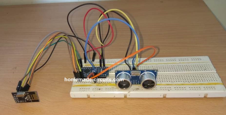
Author’s prototypes:
Transmitter:
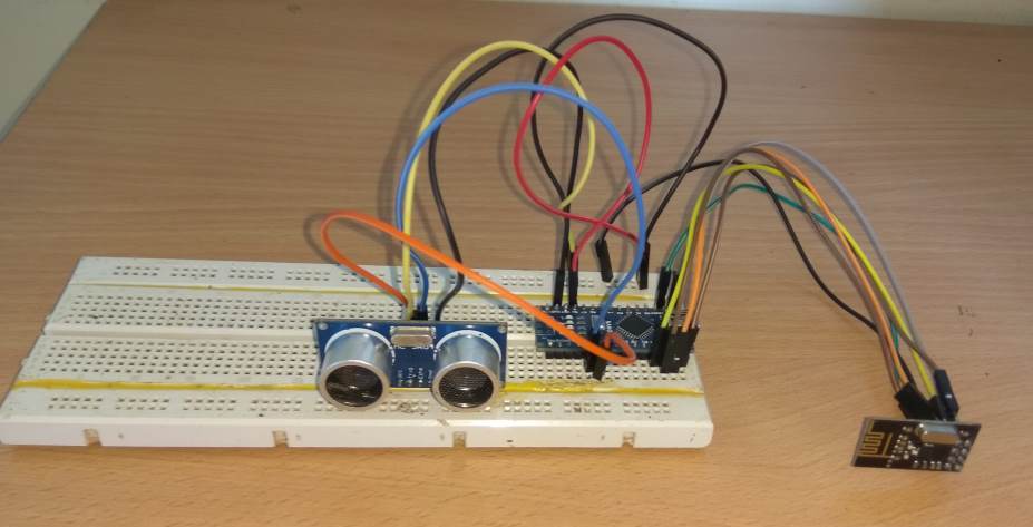
Receiver:
If you have any questions regarding this solar powered ultrasonic wireless water level controller circuit, please feel free to express in the comment, you can expect to get a quick reply.


Questions & Answers
Sir i can connect led light instead of oled display, tell me how connect 4 pin oled display nano board with wiring diagram and code for oled.
Hi Sir
Thank you for your trainings , they are useful for me that want to start this intersting routh .
can you tell me for how much distanse for wireless and deep of level can it used?
Thank you
from Iran
Thank you so much Hamid,
I appreciate your question.
However, I am sorry, I am unable to help you because my Arduino knowledge is not good and I do not have sufficient information about the subject to solve your query.
The above article was submitted by another author.
I hope some other reader here might be able to solve this problem for you.
however thank you
Can we use the digital display on place of light indicators
That will require some major modifications in the code.
Sir, much more thanks for sharing your knowledge with us. This is beautiful!
I have a question though, is it possible to operate the transmitter circuit with the regular 5v usb supply, if one chooses to use a usb charger to power it?
Thank you sir.
Thank you Damitha,
Yes the transmitter circuit can be operated using 5 V DC from USB also.
sir i need to buy one item hope this is ready to use, where can i buy
Sorry Sreenivasa, we don’t sell kits from this site at this moment.
Sir,
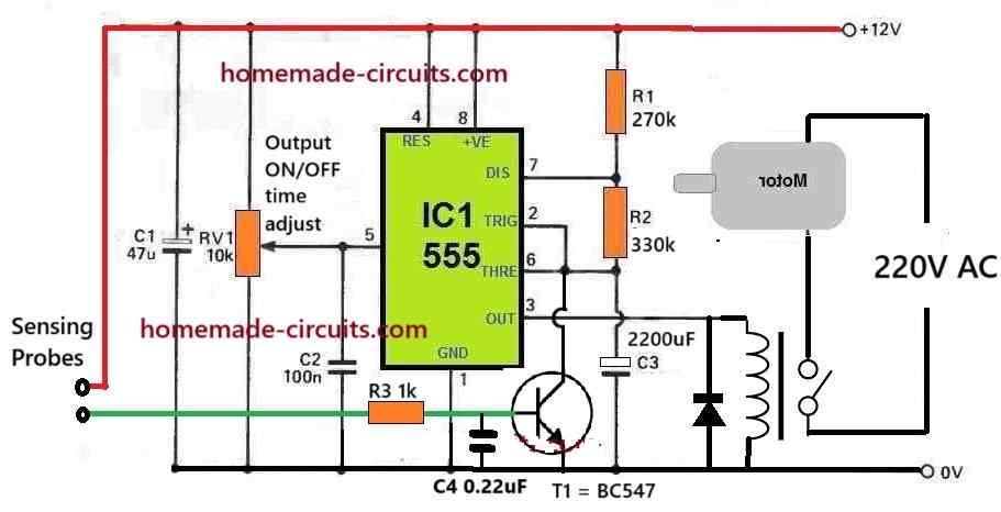
How can I control the motor using relay. Could you please provide me the circuit to do it.
Hello Rajeev, you can do it the following way:
Sir , I have uploaded the transmitter code using old bootloader ,and the receiver code using the new .the module isn’t working the LED’s aren’t blinking too.could you please help me solve this problem.
Rajeev, I am sorry I can’t help you with project since this was written by an external author, and my knowledge about Arduino is not good. The author has tested the design before submitting, so it should be a working design. You can try an Arduinio IDE software for uploading the codes, I am not sure about bootloader software.
D’not work this is sketch. Help mi!!!
This design has been tested by the author, and the codes are also compiling correctly.
Can this circuit be used to control the motor as soon as the tank gets full.
If yes then how to connect. If not then kindly suggest me a circuit for the same.
Regards,
A. Malik
Yes it is possible! Disconnect the “FULL” green LED negative pin from the ground, and connect it to the base of a relay driver stage:
Are these commercially available.pls share contact details. Thanks in advance
yes available through amazon, ebay etc
Where I can purchase
Can we add two or more receiver to the 1 transmitter
yes it may be possible
The ultrasonic sensor, HC-SR04, will be continuously exposed to the very humid atmosphere in the tank. Will the sensor be able to survive this humid environment for more than a few months?
Will this also work with tubes smaller than 1 meter?
I am testing with a Dopper bottle and set the size as follows:
float water_hold_capacity = 0.14; // up to 14 centimeter can be with water
float full_height = 0.19; // the maximum size of the Dopper bottle
The Transmitter is registering the correct measurements in the serial monitor.
The problem I have is, that the LED / LED’s never turn on (except on startup of the Arduino).
The buzzer is working because I have added a testing code in the void setup() to check it for 5 seconds.
How should I change the code of the receiver for this bottle?
Sorry, I have no idea regarding code modification.
Should the LED/LED’s always be on, or will it/they only be on when filling the tank/bottle?
When I use the serial monitor for the receiver, I get the question marks again.
You can keep it always ON so that you can continuously get the information about the level of the liquid. I am not Arduino expert so I can’t troubleshot the issue!
I followed the circuit design and uploaded the codes. However, when I open the serial monitor, I only get question marks: ? ????????
In the monitor I set the baud rate to 9600 which is the same as in the code. What am I doing wrong?
Solved: I build the circuit without the buzzer and the LEDS. Now, I get normal output in the serial monitor.
Glad it is solved!
I checked the code in my Arduino ID and it is compiling perfectly:
Done Compiling!
Sketch uses 5998 bytes (18%) of program storage space. Maximum is 32256 bytes.
Global variables use 369 bytes (18%) of dynamic memory, leaving 1679 bytes for local variables. Maximum is 2048 bytes.
Could you please add a LCD display in receiver end in this project where showing the date, time, motor status and water level (as percentage e.g. 5%, 10% ……. 100%).
Sorry, My arduino coding is not good, so I won’t be able to help you in this regard, however there are some information in the following links, which you can refer and try the procedures by yourself:
https://www.homemade-circuits.com/introduction-i2c-lcd-adapter-module/
https://www.homemade-circuits.com/learning-basic-arduino-programming-tutorial-for-the-newcomers/
Hi Swagatam,
I am Anupam Dasgupta from Dhubri, Assam. The project is very nice and in my mind I was actually looking for such a project for my overhead water tank. Though everything is fine in the code, I could not follow one thing. The messages that will be send from the transmitter section are :
text_0[] = “STOP”;
text_1[] = “FULL”;
text_2[] = “3/4”;
text_3[] = “HALF”;
text_4[] = “LOW”;
But, in the receiver section, the messages that will be received shows;
if (text[0] == ‘S’ && text[1] == ‘T’ && text[2] == ‘O’ && text[3] == ‘P’) etc.etc.
would you kindly explain it.
With regards.
text[0] in the receiver is the first character in the string text[].
The receiver must parse the incoming (received) string to determine which of the 5 possible strings has been received. The incoming string is read at the top of the loop, then evaluated by successive if() statements to find a match.
The succession of if() tests should be if() {…} else if {…} else if {…}, since no message can match more than one case. Further, only the first character of a message needs to be evaluated because every message is unique. Something like this: if (text[0] == ‘S’) { … } else if …
Hi Anupam, I am sorry I won’t be able to provide any suggestions, because my Arduino coding knowledge is not good at this moment.
sir what is the design if it’s just battery as power source instead of solar power? Because i want to design a portable device that could measure the volume of liquid inside the tank using ultrasonic sensor. Hope you could help me, thank you!
Mark, As indicated in the 2nd diagram, you can use a 9V battery instead of a solar panel….
Is the 9V battery connected to a transmitter and another battery to the receiver sir? And what should be the design if i don’t use LEDs? Just like an ultrasonic sensor that indicates a volume sensor. Hoping for your response sir thanks!
Yes, since the units are to be operated remotely, the power sources will need to be separate.
Hi Swagatam,
This is Ramana, from Hosur, Tamilnadu. I am very much impressed on your Ultrasonic Water level controller. But my doubt is whether 2nos. of Audrino is required(one each for Transmitter and Receiver or one is enough). Also if you can clarify the total Parts list for this project it would be very helpful. Please share your response.
Thanks in advance, please keep innovating with new projects.
Regards,
Ramana
Thanks Ramana, I am glad you liked the concept.
Yes you will require two separate Arduino boards as shown in the transmitter/receiver set ups. The parts will be exactly as given in the two diagrams.
Sir I like this project but one thing I want to know that can motor be connected for automatic filling of overhead tank.
Waiting for your kind reply.
Regards,
Mallik
Hi Anand, yes it is possible by configuring a set-reset relay circuit with the upper GREEN LED, and the lower RED LED.
Sir good day. Can you help me design a cricuit that uses ultrasonic sensor to measure a liquid volume in a tank without the use of arduino? It must be dc powered also sir. Thank you
Hi Mark, sorry presently we do not have a non-Arduino version of the above concept…
hi guys i need 2v input solar panel charger, is there any recommendation
Hello Mr Girish.
I am Younus from Australia.
I would propose to ask you to design and make a Prototype for our Project.
Its a portable oil Level Detection hand held unit capable to measure level remotely from a small opening say 2 inch steel pipe till a depth of say 80-100 meters with measuring accuracy of 0.1% Maximum.
Preferably using Ultrasonic waves but not necessary if have a robust and cheaper version.
We can discuss in detail If you can Possibly spare some time please.
Thanks and Regards
Younus.
you can try this:
https://www.homemade-circuits.com/solar-wind-2-input-hybrid-battery/
thanks for making user friendly circuits. can we buy circuit or pcb made by you because we don’t have knowledge of electronics
I appreciate your interest very much, however no longer manufacture PCBs or circuit modules, so can’t help in this regard.
what is max distance between sender and receiver?
Not sure about the exact distance, but since it works using radio frequency on ISM bands, the distance can be significantly long:
https://en.wikipedia.org/wiki/ISM_band
Sir what would be the cost over all approximately to this project
Pls provide the Arduino nano link, in market so many models available with different clock speeds,,, and tell me how to run with DC power directly ( without solar panel)
Could be below Rs.1000/-, you can confirm it by searching in online stores.
Ultrasonic Wireless Water Level Indicator and controller using solenoid with arduino i have 2 over head tank please give me circuit diagram with code mail id yousufh2@gmail.com