• Skip to main content
  • Skip to primary sidebar

Homemade Circuit Projects

Get free circuit help 24/7

Circuits for Beginners | Basic Circuits | LED Driver | Hobby Circuits | Transistor Circuits

New-Projects | Privacy Policy | About us | Contact | Disclaimer | Copyright | Videos

You are here: Home / Water Level Controller / Two Pipe Water Pump Valve Controller Circuit

Two Pipe Water Pump Valve Controller Circuit

Last Updated on March 13, 2019 by Swagatam 11 Comments

ask questions through comments

The article explains how to control a two pipe submersible pump valve to ensure that the pipe bringing in the municipal water is always given the main preference to the bore-well water source. The circuit is also equipped with a tank overflow cut-off feature. The idea was requested by Mr. Prashant.

Circuit Objectives and Requirements

I am big fan of your blog. I like your logic and circuit. Basically I am Soft eng but my hobby is electronic. I always read your blog and make circuit. I am happy to tell you that I have done semi-automatic water flow controller circuit from your blog and it is working from last 5 to 6 months. It saved lot of water and electricity. Thank you.

First I will brief my setup and requirement.

I have 2 pipe attached to water pump suction input point and I operate it by manually. 1st pipe is for corporation water (drinking water come daily at 5pm) and 2nd one is attached to underground water tank. So if I switch on 1st valve overhead tank will be filled by corporation water and if 2nd valve is switch on then overhead tank filled by water from underground tank.

Now my requirement is

1) Whenever corporation water come OR sense water flow in 1st pipe, water pump should start automatically and also stop suction from underground water tank so that only corporation water will be filled in overhead tank. (Just thought, can we use solenoid valve to stop water to be pulled from underground tank)

2) Stop water-pump when overhead tank is full.

3) Also I manually operate valve and store corporation drinking water in underground tank. Can we stop water pump when underwater tank is full.

The Design

The requested idea of automatically controlling a two valve submersible pump water supply can be implemented with the following schematic


Two Pipe Water Pump Valve Controller Circuit

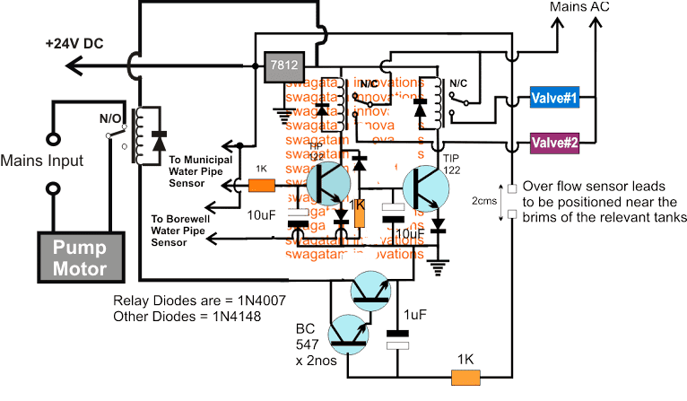
The idea is quite simple, the two relays control the two valves individually whenever the associated transistor drivers are triggered through the relevant water supply sources.

The upper left transistor's base sensor points are supposed to be attached with the municipal water pipe and this transistor relay stage becomes the preferred controller of the water supply to the overhead tank.

Anytime while the municipal water supply is active, this transistor relay stays activated, making sure that the valve#2 is opened and the municipal water is allowed to fill the overhead tank.

As long as the municipal water supply is present, the upper right side transistor relay stage is rendered inactive by the grounding of its base through the left transistor's collector.

In an event when the municipal water supply is absent, and the borewell water is present, the upper right transistor relay stage becomes active and switches ON the valve#1 enabling the pump to suck the borewell water into the associated tank.

During this time if suppose the municipal water is released, as explained earlier, the valve#1 relay is instantly deactivated by the valve#2 relay transistor, allowing the municipal water to enter the overhead tank instead of the borewell water.

The two BC547 transistors arranged in Darlington pair are used for sensing the over flow situation of the relevant tanks, whether it's the overhead tank or the underground tank, the BC547 pair instantly switches ON and grounds the base signals of the relay driver transistors, disabling the relays and the attached valves, so that the pump motor is switched OFF, and the tanks are prevented from overflowing.

The sensors could be constructed using a pair of brass rods appropriately tinned with solder and cleaned with sand paper and acetone. The distance between the sensor leads should not be more than 2cms, and should be nicely clamped over a non-conductive base

The sensors can be seen applied separately with a 24V positive to ensure an effective conduction of current across the sensor leads even in the presence of flowing water.

get free help for circuit diagrams

You'll also like:

  • 1.  How to Make a Soil Moisture Tester Circuit with a Single IC 741
  • 2.  5 Simple Water Level Controller Circuits
  • 3.  Adding a Soft Start to Water Pump Motors – Reducing Relay Burning Problems
  • 4.  5 Useful Motor Dry Run Protector Circuits Explained
  • 5.  Water/Coffee Dispenser Motor Circuit
  • 6.  Remote Controlled Wireless Water Level Controller Circuit

About Swagatam

I am an electronic engineer (dipIETE ), hobbyist, inventor, schematic/PCB designer, manufacturer. I am also the founder of the website: https://www.homemade-circuits.com/, where I love sharing my innovative circuit ideas and tutorials.
If you have any circuit related query, you may interact through comments, I'll be most happy to help!

Subscribe for the Latest Posts


Reader Interactions

Comments

    Have Questions? Please post your comments below for quick replies! Comments should be related to the above artcile Cancel reply

    Your email address will not be published. Required fields are marked *

  1. Charles says

    December 12, 2017 at 7:24 am

    Sir, good morning a very nice ckt design from Mr. Swag, wii u please specify the details of valve 1 and 2?

    Reply
    • Swag says

      December 12, 2017 at 2:48 pm

      Thanks Charles, those are “12V water pipe valves”, you can search thm on internet…

      Reply
  2. Pete Skinner says

    December 8, 2016 at 10:35 pm

    Hi Swag, in a different post you mentioned it is possible to directly swap out an SCR(thyristor) with a Triac. I have replaced a XL1225 with a 2n6073a in a simple night light circuit with no luck. Do you know why its not working? Let me know how to send schematic if required. Sorry if this is the incorrect way to ask unrelated questions.

    Reply
    • Swagatam says

      December 9, 2016 at 11:30 am

      Hi Pete, an SCR can be replaced with a triac, since both are almost similar with their properties except the fact that SCR conducts only one half AC cycle while a triac conducts both the cycles.

      you might have connected the leads wrongly, connect an LED in series with the gate and see how the lED erspo0nds to the gate trigger.

      you can also try changing the triac entirely and check again

      schematic can be sent to my email

      admin @ homemade-circuits.com

      Reply
  3. prashant zingade says

    December 6, 2016 at 7:27 pm

    Two relay in design is use to control valve. Which relay is used to stop water pump ?
    Pl advise

    Reply
    • Swagatam says

      December 7, 2016 at 3:34 am

      yes I think the diagram needs a correction, I got confused with the valve and motor operations…will correct it soon.

      Reply
  4. musa kizito says

    December 6, 2016 at 8:44 am

    Good day sir. Does 'akula generator' really works? If yes, please I want you to help me with a working circuit diagram. Thank you Sir, for your good work.

    Reply
    • Swagatam says

      December 6, 2016 at 3:22 pm

      goodday Musa…the answer is No, it simply doesn't

      Reply
    • musa kizito says

      December 9, 2016 at 1:24 am

      Thanks

      Reply
  5. prashant zingade says

    December 5, 2016 at 8:58 am

    Can we add dry run protection in this circuit?

    Reply
    • Swagatam says

      December 5, 2016 at 3:35 pm

      the motor will run only when water is present inside the pipes, so the feature is already there in the design…

      Reply

Primary Sidebar


Categories

  • 3-Phase Power (15)
  • 324 IC Circuits (19)
  • 4017 IC Circuits (52)
  • 4060 IC Circuits (25)
  • 555 IC Circuits (98)
  • 741 IC Circuits (19)
  • Amplifiers (59)
  • Arduino Engineering Projects (83)
  • Audio Projects (94)
  • Battery Chargers (83)
  • Car and Motorcycle (94)
  • Datasheets (46)
  • Decorative Lighting (Diwali, Christmas) (32)
  • DIY LED Projects (89)
  • Electronic Components (97)
  • Electronic Devices and Circuit Theory (35)
  • Electronics Tutorial (109)
  • Fish Aquarium (5)
  • Free Energy (34)
  • Fun Projects (12)
  • GSM Projects (9)
  • Health Related (19)
  • Heater Controllers (28)
  • Home Electrical Circuits (100)
  • How to Articles (20)
  • Incubator Related (6)
  • Industrial Electronics (28)
  • Infrared (IR) (40)
  • Inverter Circuits (98)
  • Laser Projects (12)
  • LM317/LM338 (21)
  • LM3915 IC (25)
  • Meters and Testers (64)
  • Mini Projects (156)
  • Motor Controller (66)
  • MPPT (7)
  • Oscillator Circuits (24)
  • PIR (Passive Infrared) (8)
  • Power Electronics (33)
  • Power Supply Circuits (74)
  • Radio Circuits (9)
  • Remote Control (47)
  • Security and Alarm (61)
  • Sensors and Detectors (118)
  • SG3525 IC (5)
  • Simple Circuits (74)
  • SMPS (29)
  • Solar Controllers (60)
  • Timer and Delay Relay (53)
  • TL494 IC (5)
  • Transformerless Power Supply (8)
  • Transmitter Circuits (40)
  • Ultrasonic Projects (14)
  • Water Level Controller (45)


Circuit Calculators

  • AWG to Millimeter Converter
  • Battery Back up Time Calculator
  • Capacitance Reactance Calculator
  • IC 555 Astable Calculator
  • IC 555 Monostable Calculator
  • Inductance Calculator
  • LC Resonance Calculator
  • LM317, LM338, LM396 Calculator
  • Ohm’s Law Calculator
  • Phase Angle Phase Shift Calculator
  • Power Factor (PF) Calculator
  • Reactance Calculator
  • Small Signal Transistor(BJT) and Diode Quick Datasheet
  • Transistor Astable Calculator
  • Transistor base Resistor Calculator
  • Voltage Divider Calculator
  • Wire Current Calculator
  • Zener Diode Calculator


You can also Chat with me here:

Facebook
Twitter
YouTube
Instagram
My Facebook-Page
Quora


© 2022 · Swagatam Innovations

We use cookies on our website to give you the best experience.
Cookie settingsAccept All
Privacy & Cookies Policy

Privacy Overview

This website uses cookies to improve your experience while you navigate through the website. Please visit the Privacy Policy Page for more info.
Necessary
Always Enabled
Necessary cookies are absolutely essential for the website to function properly. This category only includes cookies that ensures basic functionalities and security features of the website. These cookies do not store any personal information.
Non-necessary
Any cookies that may not be particularly necessary for the website to function and is used specifically to collect user personal data via analytics, ads, other embedded contents are termed as non-necessary cookies. It is mandatory to procure user consent prior to running these cookies on your website.
SAVE & ACCEPT