In this post I have explained how to build a few simple monostable circuits using only transistors, and also learn how to make practical application circuits with them.
If you search for transistor monostable circuit online, you will find that one typical circuit has been discussed in all the online articles. This circuit looks a bit complex, with no practical applications.
In contrast, the designs explained in the following article are simple, highly efficient, accurate and can be customized for building many useful practical application circuits.
What is a Transistor Monostable
A monostable circuit built using transistors is called a transistor monostable circuit.
As the term monostable suggests, the design exhibits a single stable state. Meaning, when the circuit is triggered through an external momentary signal, it produces a momentary output with a single, one-shot ON period, which switches OFF permanently after some delay, until triggered again.
The length of this ON period is determined by the values of an existing RC (resistor, capacitor) network of the circuit.
Using a Single Transistor
A transistor monostable using a single transistor can be seen in the following image:
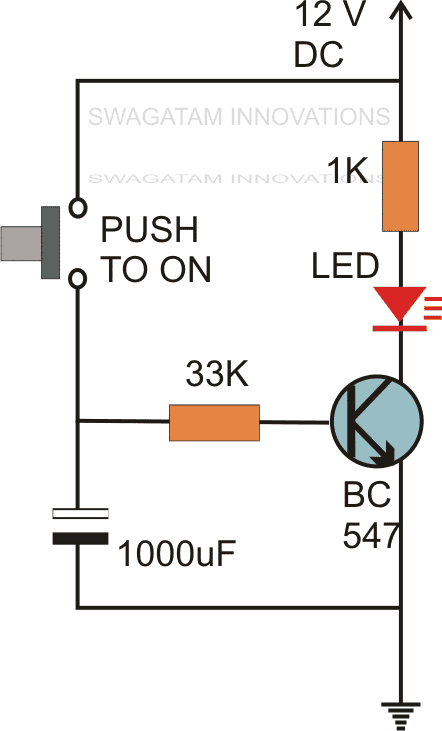
When the push button is pressed and released momentarily, the 1000uF capacitor is charged and holds the base of the transistor with a positive potential so that it switches ON.
Because the transistor is switched ON, the LED is also switched ON.
The transistor remains in this switched ON condition until the 1000uF capacitor is fully discharged via the 33K and the transistor emitter pin.
So the time delay for which the above monostable remains in the conduction mode is determined by the values of the 1000uF capacitor and the 33K resistor.
There's one major drawback of the above circuit.
The monostable delay action can initiate only once the push button is released. If the push button is held pressed, then the monostable delay action will not initiate and the circuit will remain switched ON as long as the push button is held pressed.
This drawback is eliminated in the following two transistor monostable circuit
Using Two Transistors
The following circuit diagram illustrates a simple transistor monostable circuit using a push button.
When the push button is pushed and released momentarily, the LED is instant illuminated which stays illuminated for sometime and then shuts off. The time for which the LED stays illuminated is decided by the components R3 and C2.
The actual working of the above transistor monostable circuit can be understood through the following points:
Initially T1 is in the switched ON mode due to the bias current through R3, R2. Due to this T2 is rendered switched OFF, since its base is grounded via T1's collector.
Now, if the push button is pressed, the T1 base is momentarily grounded via C1.
This causes T1 to switch OFF instantaneously.
With T1 switched OFF, T2 switches ON, and connects the base of T1 to ground via its collector, R2 and C2.
The T1 now cannot revert to conduction and remains switched OFF due to latching effect created by transistor T2.
However in the process C2 begins charging via resistor R3, and as soon as it charges up to 0.7 V, T1 base gets the required amount of potential difference to turn ON.
When T1 turns ON, T2 turns OFF breaking the latch, the LED now shuts off finishing the monostable time delay cycle.
If the push button is pressed again, the above cycle is repeated yet again.
Upgrading with a Relay
The above explained circuit consists of an LED as the indicator for the monstable action which cannot do any useful work.
In order to make the above transistorized monostable do some useful work, such as switch a load ON/OFF, it can be upgraded with a relay as shown in the following diagram:
In this design the previous monostable circuit can be seen upgraded with a relay driver stage using T3 and the relay.
Now this upgraded transistor monostable can be used for switching any desired load through the relay, such as lamps, solenoids, induction heaters, water sprinklers, etc.
Although the above designs looks pretty simple, they can be used for building many useful application circuits, as explained in the following paragraphs:
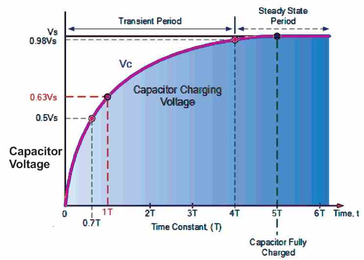
Calculating the Monostable Delay Time
The C2, R3 form the RC time constant components which determines delay OFF period of the monostable circuit. The RC time constant formula is given by:
T = RC, where C is in farads and R is in Ohms
Considering R = 3M3, C = 1uF, we can calculate the time constant as:
T = 3300000 x 0.000001 = 3.3 seconds
This is the approximate time the capacitor will need for reaching 1T time constant.
Referring to the time constant graph below, we find that after at around 1T time constant, the voltage across the capacitor will reach around 0.63 V, which is actually the perfect switch ON potential for T1. Meaning, if the R3, C2 values are 3M3, and 1uF respectively T1 will switch ON to its original state after approximately 3.3 seconds causing the output of the monostable to switch OFF.
Applications Circuits
A few important application circuits which can be built using the above transistor monostable circuit are:
- Door Bell
- Induction Heater Timer
- Dog Barking preventer
- Door Alarm
- Clap Operated Staircase Lamp Timer
- Burglar Alarm Circuit
Door Bell Controller
A door bell with a timer makes sure that when the door button is pressed, the door bell sounds for a few seconds and then stops. The explained transistor monostable can be simply used for making a door bell timer circuit as shown in the following figure:

The door bell can be any 12V musical doorbell, and the DC supply can be taken from a 12V AC to DC adapter.
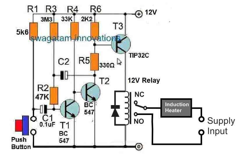
Induction Heater Timer
Induction heating is very useful in industrial application where metals are required to be melted or heated for some specified time to obtain the intended results. The timing of the heating in such applications becomes very crucial.
The discussed transistor monostable timer can be also suitably applied for controlling the ON time of an induction heater, using the following circuit diagram:
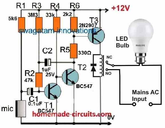
Dog Barking Preventer
A very efficient dog barking preventer circuit can be built using the above transistor monostable circuit, simply by replacing the push button with a MIC.
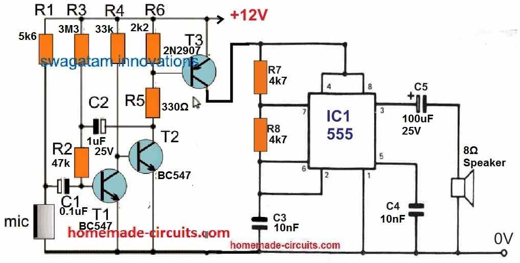
When a loud sound like the barking of a dog is created, it hits the MIC which activates the transistor monostable. This switches ON T3 momentarily, which in turn switches ON the attached IC 555 astable circuit for a couple of seconds depending on the value of C2.
The IC 555 astable generates a counter-repulsive tone in the form of a sharp frequency which causes the dog to become alert and stop barking. When the dog barks again, the monostable is triggered again repeating the action, which causes the dog to stop barking yet again.
This repeated interference, whenever the dog barks causes the dog to get irritated and vacate the space quickly.
The values of R7, R8, C3 generates a 10 kHz tone from the astable, which may be quite loudly audible to the dog, but quite low to a human ear.
Clap Operated Staircase Lamp Timer
A very novel circuit application which will switch ON a lamp in response to a clap sound can be built using the above discussed transistor monostable concept.
The lamp can be positioned ideally within a staircase or a corridor of a building, or in the garden or porch area of a bungalow.
In fact, this automatic clap operated lamp can be placed in any location as desired, even in your bedroom or bathroom.
When a clap sound is created, the MIC responds and activates the the transistors of the monostable causing the relay to operate. The relay switches ON the LED lamp, which remains operative for some moments and switches OFF automatically until the next clap sound is made.
Burglar Alarm Circuit
Another cool application of the above described transistor monostable circuit is the micro-switch operated burglar alarm circuit.
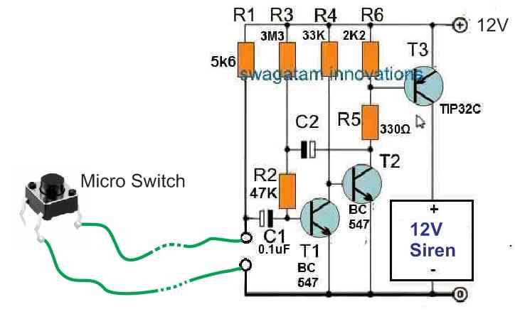
The idea is simple, the push button is replaced with a micro-switch which could be hidden under a carpet or a door mat through a shielded cable, and the monostable alarm circuit kept in near vicinity, may be under a nearby table or sofa set.
Once armed, if a possible intruder or a burglar steps on the micro switch, the micro-switch activates the transistor monostable circuit causing the attached siren to switch ON. After some delay when the monostable time elapses the siren is automatically shut off. Nevertheless, by the time the siren shuts off, the burglar is already caught red handed by the owner of the premises.
So these were a few example application circuits built using the explained transistor monostable design. However, there could be possibly many more application circuits which could be designed to work with this concept. If you have any special design in your mind, let us know through your valuable comment below.

Comments
seara buna ,o comanda sonora cu temporizare de 1 -2 minute prin montarea unui electrolitic la Temporizator cu lampă cu scară unde se pune????
Hello Mr. Swagatam!
I built the relay upgraded – three transistors – version. It works well with smaller timing capacitors. But I want bigger ones – 1000uF to operate. This causes a problem. It needs time to start the circuit again. How can I ensure a complete discharge of the timing capacitor C2? I have yet one more question. Sometimes I need to reset the circuit before the end of programmed time. I tried to short C1 but it is not work perfectly because it is impossible to start it again immediately. If you could, please help me.
(P.S.: I know I could use integrated circuits – NE555, CD4060, CD4047 – but I have a tons of various transistors.)
Thanks for your attention on me.
Hello Federics,
The C2 has an awkward position and I cannot figure out a suitable way to discharge it when the circuit is switched OFF.
However, I have another circuit which can be perhaps used for similar implementation and it has a discharge facility.
You can refer to the Two transistor circuit explained in the following article”
https://www.homemade-circuits.com/how-to-make-long-duration-timer-circuit/
You can reset this circuit by shorting the 1000uf capacitor.
Let me know if you have any further doubts
Hello Mr. Swagatam!
Your reply was as fast as a lightning. Thanks for it. I’m taking your advice and going to build the recommended two transistors version as soon as possible. I promise, I will inform you all about my experiences (if I don’t disturb you with them).
Anyway your site is fantastic, I learn a lot from your circuits. Your explanations are understandable well and detailed. To learn electronics by your help is much more easier than to do it only from books. I hope you never turn your back on teaching electronics and me and millions of fan of electronics in the world can improve their knowledge by building your circuits for a long-long time.
Thanks again – one of your enthusiastic reader from Hungary: Federics István
Thank you so much Federics,
I am glad to help you.
I appreciate your interest very much.
I wish you all the best.
Let me know if you any problems.
Sorry for not being about subject, but contact page doesn’t seem to work for me, sent mail at hitman2008 few days ago with project idea, and not sure if even been read
I think it was a bicycle related question, so please post your question under bicycle project from this blog…you can use the search box to find the suitable project for the comment.
Hi my friend!!!
What can replace the transistor TIP32? There is no such transistor in my region.
Thanks!
You can replace it with 2N2907
Greetings!!
In the circuit “preventive dog barking circuit”, you can trigger a ci 4017 which would make a sequential with a total time of 90s.
Thanks for the suggestion, appreciate it, however we need the output to be active only for a few seconds, so I think its fine to use a single IC IC 555
Hello Swagatam,
Sorry I don’t think I can make myself understand, I’ll try to explain: I have a sequential circuit with a 555 (astavel) and 4017, working perfectly. What I need is for the 555 to start working with an external pulse, so I asked if this circuit you presented could trigger the 555 for 90s, which would be the time for the 4017 to execute the sequential and stop, the main function would be to trigger the 555 with an external pulse.
Thanks Carlos, for the clarification. Yes you can use the above circuit for holding the IC 555 astable for executing a 90 second sequence across the 4017 IC.
Hello, I greet you from Caldera in the north of Chile. I am self-taught and have built this device before in a much more complex (and expensive) way. Thank you for simplifying my life…
Thank you for sharing your useful feedback!
It’s very interesting, thank you. It’s been a long time, how are you doing?
Thank you for liking the post, I am good!
Hello,
Very good idea to start from a simple principle diagrams and to elaborate
several practical applications. this allows the beginner that I am to learn
with more ease and in a very pleasant atmosphere.
Question: In the “anti-barking” case, what are the characteristics of the microphone used?
Good continuation to you and good morning from Belgium.
Hi, thanks for reading this post! appreciate it! The mic is an ordinary electret MIC
Thank you awesome stuff, simple but so valuable I’m in Heavy Curent , but finding more & more communication & instrumentation being needed in my career. Makes me wonder if I shouldn’t of studied electronics instead!
Thanks for reading this article, and glad you liked it. You can still learn electronics, it’s indeed an intriguing subject.
Hi. Thanks a lot for your article. I learned a lot step by step.
Regards
Mr Waka
You are most welcome! Glad you could learn from the article.