In this post I have explained a timer circuit for submersible borewell pumpset which alternately switches the pumpset ON/OFF at a predetermined rate in order to allow the ground water sufficient time to restore at regular intervals and to ensure a consistent water supply to the attached overhead tank. The idea was requested by Mr. Siva.
Circuit Objectives and Requirements
- I want to run a submersible pumpset only in 3 phase with major interval of 1 hour interval duration. There is no available ground water supply for continuous running for the pump.
- So i need a AC circuit to operate automatically timely for 1 hour running & 1 hour idle.
- Please provide a circuit to operate without any drawbacks because if anything happens wrongly need to spend more money & time to resolve it.
- More than that only source of water for us(borewell only).
Pump Specifications
100mm(4")borewell submersible pumpset
Motor
Type:TBRF1545+TF045H
Hp/Kw:6.00/4.50
Power:3 phase A.C
Rpm :2850
PUMP
Type:TBRF1545+TF045H
Hp/Kw:6.00/4.50
Rpm :2850
No.of stage:45
Designing the Pump Timer Circuit
The requested submersible bore well pump timer circuit can be simply built using a single IC 4060 timer circuit and a relay, as indicated below
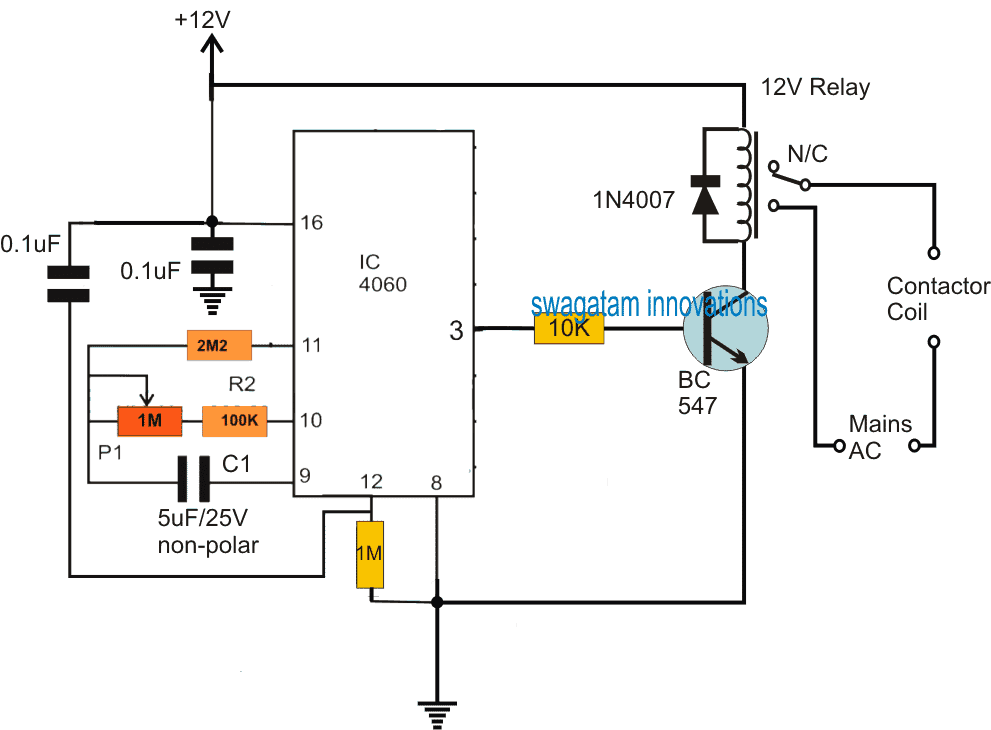
As may be seen in the above diagram, the IC 4060 is wired as a simple timer circuit whose timing limit is determined by the combined values of C1 and of P1/R1.
P1 can be adjusted for getting any desired delay ON/OFF at pin#3 of the IC, within a stipulated range.
Since the IC is configured as a free running astable multivibrator, the ON/OFF delays at the output pin#3 continues to toggle the transistor driver stage and the relay infinitely as long as power is available to the circuit.
If as per the specifications, P1 is adjusted to obtain a 1 hour ON/OFF delay at pin#3, the relay could be expected to switch ON/OFF at the same rate continuously as long as the circuit may remain powered.
The relay contacts can be seen wired with the 3 phase motor's contactor coil, which correspondingly operates at an identical delay rate during the course of ON/OFF switching.
This results in the switch ON and OFF of the borewell motor at a precise interval of 1 hour, which in turn makes sure that the ground water gets ample time to replenish and enable a sustained water supply for the motor to pump in.
Other time delays may be achieved for the proposed submersible pumpset timer circuit by appropriately adjusting P1, as per the given specifications or the ground water conditions.
Calculating the Time Delay
It could be determined using the formula:
f(osc) = 1 / 2.3 x Rt x Ct
The resistors at pin#10 correspond to Rt
C1 corresponds Ct


Questions & Answers
You are doing so well and I appreciate your effort. Can you kindly furnish me with a 20amps 12.8volts Solar Lithium Battery charger?
Sure, you can try the first circuit from the following article:
https://www.homemade-circuits.com/charging-li-ion-battery-12v-car/
If you have any further questions, please feel free to ask under the above linked article.
Hello good afternoon Mr. Swagatam, in this opportunity I want to ask you if you have any simple circuit maybe with Lm555 cascade timer. That is, when the time of the first one ends, the second one starts and so on…. Let’s say 3 or 4 different times. Thank you very much
Hello Mr. Carlos, here’s a circuit of a cascaded 555 timer, although it is not designed by me, it looks like it should work as expected:
Can you please give me CD4060 based timer circuit that when switch on initially “on” for 30 seconds then “off” for 5 minutes then again on for 30 seconds & off for 5 minutes, & these cycles continuously goes on & resets when switch off the timer circuit.
Surely I can help. You can try the first design from this article:
https://www.homemade-circuits.com/how-to-make-simple-programmable-timer/
But Sir that circuit doesn’t start load immediately after power on the timer, please help me to way out.
You are correct, in that case you can replace the upper BC547 with a PNP BC557 as shown in the following diagram:
Thank you very much sir.
One more question sir. where to connect ic’s counting indicator LEDs?
You can connect it between between pin#14 and ground or pin#15 and ground. Use a 1K series resistor with the LED
Thank you very much Sir for your prompt reply.
My pleasure!
i need a circuit which should be of delay off;with 15 minutes adjustable timing plz any provision for pcbs availiability,thanks ind advance
Please see the second last design from the following article, which uses only transistors:
https://www.homemade-circuits.com/how-to-make-long-duration-timer-circuit/
Hi There,
I have a 3 Phase Bore Reticulation system and would like to install the Rainbird Wifi controler as you can see on this website.
Our bore sprinkler system is currently operated manually with an on / off switch, I want to fit a fully automatic reticulation controller and interface it to start mybore. “Commonly this involves our electrician fitting a 24 volt start relay or contactor to the existing 3 phase DOL ( Direct Online Starter) or single phase start box. Where you may currently switch from one section to another by manual gate valves or taps we can install automatic solenoid valves. Compliance with your rostered water days then becomes automatic.”
Reticulation controllers ( timers ) are powered by mains power 240v but have a battery back up so that even in the event of a power failure the programmed memory is retained. This allows you to leave the property for extended periods safe in the knowledge that your irrigation system is programmed to come on automatically.
Hi, sorry I do not have this specific circuit design with me at the moment….if I happen to find it, will update it for you soon…
sir i want to create a timer whose time period can be varied with pot for 2 hrs and must repeat (for fish tank purifier pump it has to be switched on for every 2 hrs and switched off for every 2 hrs and this on time must be able to vary with the help of pot to 1 hr or 45 mins) can u please help
Mithun, you can use IC 4060 based timer, as explained in the following artciles:
IC 4060 Pinouts Explained
Simple Timer Circuit Using IC 4060
thank u sir : )
do not use the 1N4148 feedback from pin3 to pin11 if you want the output to cycle ON/OFF every 2 hours
Hello Mr. Swagatam thanks for your quick reply. Well basically what I want is a circuit with 2 relays when a button is pressed the first relay is energized for 24/36 hours, then it stops and the other relay also starts for 24/36 hours cyclically. Thank you very much
Mr. Carlos, You can try the following circuit:
for another alternate relay you may have to repeat and add another BC547 the transistor relay stage, by connecting its base resistor with the collector of the existing BC547.
For getting 24 hour timing you may have to use a 22uF PPC non-polar capacitor or higher in place of C1.
…please remove the 1N4148 diode feedback link otherwise the circuit will not cycle ON/OFF.
Good day Mr Swagatam….
I was in the market today but I couldn’t get the 5uf ceramic capacitor, I could only get 0.1uf.
1) what modifications can I make to the R-C set up to get good time range.
2) I also want to know if the inverse of this formula
( f(osc) = 1 / 2.3 x Rt x Ct ) is the given time the counter will take before it toggles between high and low positions at pin #3.
3) If (2) is yes, is the value of the inverse of the formula
( f(osc) = 1 / 2.3 x Rt x Ct ) in hours or seconds?
As always thanks for the help, hope to hear from you soon.
Hello good afternoon, my name is Carlos and I am from Buenos Aires Argentina. Can you help me with a circuit? I need to activate 2 water pumps alternately every 24/36 hours .. Thank you very much.
Hello Carlos, what kind of switching arrangement due you have for the pumps, is it a start/stop type or simple ON/OFF MCB
Good day Rob,
you can use two 22uF in series with their identical pins connected together, meaning connect either (-)(-) or (+)(+) together, and use the free end terminals in the circuit.
1) You can refer to this article where I have explained “Calculating RC Timing Components” using a simple manual technique
https://www.homemade-circuits.com/how-to-make-simple-programmable-timer/
2) f(osc) is the number of ON/OFF cycles per second across Ct or the capacitor at pin#9
3) instead of using the formula you can use the step1 manual idea which is much easier and hassle free.
Is there any ro water purification control circuit?
sorry, presently this concept has not been discussed here!
I didn’t get 5uf/25v non polarized, which other capacitor can I use
Is it 105/25v or 250v
If 105/25 is available, you can use it.
use 5nos of 105/250V caps in parallel
Dear sir.
thanks for this project, Please i need your help, how can i have a timer circuit that goes on and off contineusly and adjustable time interval, then also do you have a circuit that charges a battery and when the battery is fully charged it cuts off the supply? i need that for my emergency light.
thanks and waiting to read from you…
This the best website ever…. Kudus to you sir.
Nkwenti.
Hi Nkwenti,
You can try the following concept for the timer application
https://www.homemade-circuits.com/how-to-make-simple-programmable-timer/
I have plenty of battery charger articles published in this website, you can select the appropriate one from the following list:
https://www.homemade-circuits.com/automatic-battery-charger-circuits-you-can-build-at-home/
You are most welcome, I am glad you are liking this website 🙂
You are the high tech player in the electronics industry. Thank you for sharing the 4060 timer ic.
thanks I am glad you found it useful…
Good Evening Sir,
This is Vijay from bangalore, I need some clearance regarding that CONTACTOR COIL in tha circuit….??
Is that default in relay or we have to connection separately???
Hi Ganesh, the contactor coil is a part of the submersible pump starter box, this coil needs to be energized through mains AC to operate the pump and vice versa.
sir, Thanks for your valuable response & for the circuit design. I will surely try this circuit then i will ask any doubt related this circuit issue.
Siva, I am sorry I having difficulty in understanding your requirement, so please explain it again point-wise 1)…2)..3)… to make it clearer.
However, pausing a timer during a power failure could be difficult I don't think that would be easy using discrete components.
You are welcome Siva!