In this post I have explained an aquarium feeder timer circuit which sustains a set of continuous operations as per a predetermined timing sequence through the respective pot controls. The idea was requested by Mr. Mike.
Technical Specifications
I am trying to build a timer circuit to control an automatic fish feeder. It needs to operate on 12 volts. It needs to operate two relays. Both need to come on at the same time.
The first relay needs to shut off after 5.2 seconds. The second relay needs to shut off after 7 seconds. Then the process needs to repeat in 24 hours. Also can you convert 16 volts ac into 12 volts dc.
Thank you Mike
Circuit Diagram
The Design
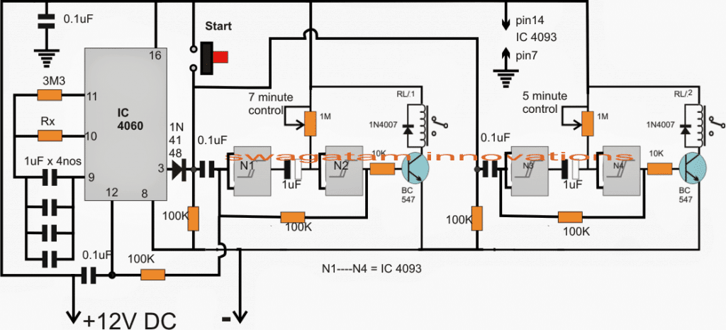
As shown in the proposed fish feeder timer controller circuit, N1, N2 and N3, N4 are the four NAND gates from the IC 4093, configured as flip flop timer stages.
N1, N2 forms the 7 second delay timer, the period may be adjusted and set with the help of the 1M pot, identically N3, N4 is wired up as the second 5.2 second delay generator stage.
IC 4060 is designed as the 24 hour timer circuit for the required cycling of the desired time sequences.
When the circuit is powered, the 0.1uF capacitors at the inputs of N1 and N3 ground the respective inputs via the 100k resistors, rendering a negative latch across gate outputs, which in turn keep transistor relay driver switched OFF.
Now, for initiating the circuit the "start" button is pressed which reverts the gate latches to positive switching ON the relays simultaneously. This condition forces pin12 of IC 4060 to become high so that it stays disabled for the time being.
As per the proposed settings of the 1M pots, after about 5 minutes the capacitor at the N3 output charges up first forcing the N4 input to go high which yet again restores the latch to negative switching off the 5 second relay first, exactly in the same manner N2 relay follows and gets switched OFF after next 2 seconds.
The above situation causes the output of N2 and the input of N1 to go "low" which means now pin12 of IC 4060 is enabled at the required "low" allowing it to begin its counting until the stipulated 24 hour time is elapsed, when its pin3 goes high causing an automatic triggering of the above explained cycle.
The process now keeps repeating indefinitely as long as the aquarium feeder circuit is held in the powered state.


Questions & Answers
0.1uf to n1.4093 ic which pin number connected sir
which gate you want to use for N1 out of the four inside the IC? according to your selection you can either use pin1/2, or pin5/6, pin9/8, pin12/13 as the inputs….depends which gate you want to use in that position, all gates are same with their properties, you can use any gate anywhere across N1—-N4….
Sir fish feeder circuit iam not understand properly pls send me sir with ic pin connect track and parts names pls.
you can there are 2 inputs shorted on side and one output terminating from the other side of the N1, N2…squares? right,
if you see the 4093 image as shown below, you will find each of the gates have two inputs and one output, you just have to use these two inputs and one output pins of the respective gates and connect them across the shown N1—-N4 gates in the diagram
remember the above shown circuit is not for the newcomers, it is for those who are well versed with all the basics of electronics, so proceed with caution.
Sir fish feed circuit OK but.how to connect n1.n2.n3 n4 4093 ic Which pin number connect
tell me sir
hello sir,,thank you for the design.But one question arises that WHERE SHOULD WE KEEP THE FISH FOOD? n FROM WHERE WE CAN GET THAT FOOD IT OUT?
Help me in this regard,Thank you again.
Hello Seema, the above designed circuit is the controller module for the feeder motor mechanism which is supposed carry the fish food.
the mechanism details have not been furnished in the above article, only the circuit controller stage is explained
Hi Swagatam,
thanks for this needy design, one request – If I want to feed the fish twice (morning/evening) what will be the changes we will have to make.
Regards
Gopal
Sir pls help me project
prawn autofeeder on of cycle timer.
In 2.12v dc motor run pls circuit sir
sreenu, here’ the circuit you can apply for your project
https://www.homemade-circuits.com/how-to-make-incubator-timer-egg/
..sorry the upper IC should be set for achieving 12 hour delays.
Thanks Gopal,
The above design is specific to the application and may not suit your requirement.
rather you could try the following design:
https://www.homemade-circuits.com/2012/04/how-to-make-simple-programmable-timer.html
The upper timer could be set for generating 6 hour delays while the lower IC could be adjusted as per the feeder mechanism ON time specs.
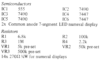
Swagatam, Thank you for the speedy design. I will start to build the circuit tomorrow. I do have two questions. What is the value of the resistor rx at pin 10 and what does 4nos at pin 9 mean? Also the two pots to input to the gates say 7 min and 5 min. Are they really 7 and 5 seconds?
Thank you,
Mike
You are welcome Mike! Rx can be calculated using the T(out) formula as given here:
3.bp.blogspot.com/-dbqcQmPNhIA/UREWILIHRWI/AAAAAAAAC8w/ab6ny7Q4P2I/s1600/4060+frequency+formula.png
Or could be found through some trial and error….first try any arbitrary Rx with a relatively smaller value resistor and see after how many minutes pin3 of 4060 becomes high, once you achieve this example duration you could try finding the proportionate 24 hour resistor value for Rx by comparing the example timing.
pin9 carries 4nos of 1uF non polar capacitors which in conjunction with Rx determine the intended 24 hour delay for the IC, changing either one of these would change the timing response of the IC….the response can be assumed to be very linear