In this post I am going to explain solar road stud light, what is it? How do they work? And how can we construct our own.
In this post we will see the following:
- What are road stud lights?
- What are active and passive solar road stud lights?
- Circuit design and diagram.
- Flashing stud lights and non-flashing stud lights.
- Types of batteries utilized and it’s charging procedure.
What are road stud lights?

Road stud lights are reflective devices that are implanted on roads for safety during the night time for guiding the vehicles to maintain their lane and also to keep track of the road.
Stud lights are usually placed on the lane marks / center of the road. Stud lights are really helpful for motorists during the night where there are no road lights installed and also when our normal visibility is hindered during rain or snow.
The stud light was invented by Percy Shaw and he patented his invention in 1934; the stud lights we see on the road today may be different from the original design however the working principle remains the same.
Stud lights are made with heavy duty plastic material where it is resistant against temperature of roads during peak summer without melting, strong enough to withstand several thousands of vehicles running over it on a daily basis and lasts several years before they need to be replaced.
What are passive and active road stud light types?
Passive type:
The first ever road stud light design was a passive type, meaning they don’t emit their own light, it simply reflects the light from your headlights efficiently towards you. Even today passive road stud lights are used widely due to their zero maintenance.
Active type:
The active stud lights are powered using rechargeable batteries and instead of using reflective materials, LEDs are used. It flashes the light several times a second or maintains steady illumination on the roads. It automatically lights up when it detects no or faint sunlight.
It gets its power from solar cells / panels built into them and it uses rechargeable batteries like li-ion or Ni-MH or Ni-Cd. The average life spans of solar road stud lights are 3 to 5 years.
Circuit diagram of flashing solar stud light:
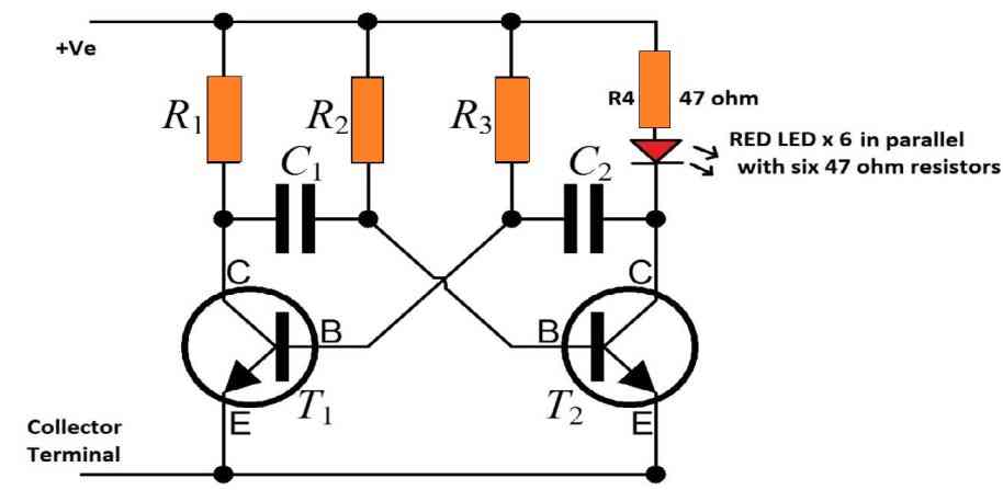
Values:
T1 & T2 = BC 548
C1 & C2 = 2.2uF / 16V
R1 & R2 & R3 = 1K ohm
R4 = 47 ohm
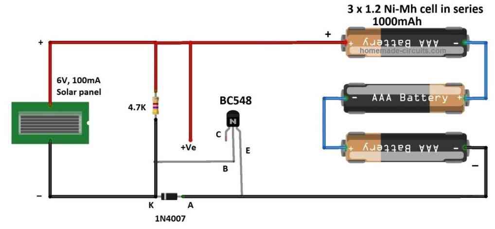
The proposed circuit design has two parts; the first one is responsible for charging during the day time and discharging during night time.
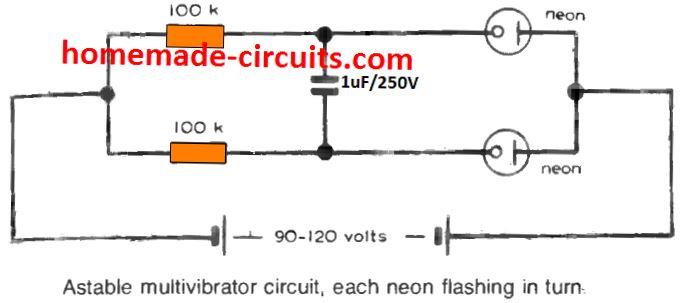
The second circuit is called astable multivibrator which is responsible for flashing the LEDs several times a second.
Let’s try to understand the circuit design that is responsible for charging and discharging.
The circuit consists of a solar panel rated for 6 V and 100 mA, a low power NPN transistor, a silicon diode, a biasing resistor and three AA 1.2V Ni-MH connected in series.
Now let’s consider the case for day time:
When the solar panel is producing power, the battery starts charging at around 80 to 100 mA, the +Ve of the solar panel is directly connected to +Ve terminal of the battery, the negative terminal of the solar panel is connected to the diode which gets forward biased and conducts power to the battery.
The transistor stays off when the solar panel is generating power during the day time; this is because the negative of the solar panel is directly connected to the base of the transistor which makes it reverse biased (we need positive voltage above 0.7V to make the transistor ON).
Night time:
During night time the solar panel stops producing power and the battery starts providing power for the circuit.
Now the diode gets reverse biased as the negative supply from the battery is connected to anode of the diode, hence the negative supply will not reach the base terminal of the transistor.
The diode also plays an important role in protecting the solar panel from the supply of the battery.
Now, if we look at the positive supply from the battery, it is connected to the base of the transistor with a 4.7K current limiting resistor.
Now there is a steady +Ve voltage at the base terminal which will turn on the transistor and negative supply from the battery is available at the collector terminal of the transistor and now it can turn ON the multivibrator circuit which flashes the LEDs.
From our practical setup we found that when the solar panel voltage falls below 3.1V the transistor start conducting partially and when the voltage falls to 2.9V the transistor is fully turned ON.
From this observation we can say that the proposed stud light circuit starts working before the sun sets fully or even when there is dull artificial light around the circuit setup, this signifies that the circuit won’t falsely recognize a street light for sunlight and interfere in its functionality.
Astable Multivibrator:
The flashing of LED lights is achieved using a transistor based multivibrator circuit. The multivibrator needs to flash 6 LEDs (3 on one side and other 3 on the opposite side of the stud), all the LEDs should blink at the same time.
The proposed multivibrator circuit flashes at 3 Hz or 3 flashes per second and this flash rate is achieved by selecting the capacitors as 2.2 uF and resistors as 1 K ohm.
The time period formula for transistor based astable multivibrator is:
T = 1 / (1.38 x R x C)
Assume R2 and R3 = 1000 ohm and C1 and C2 = 2.2 uf
T = 1 / 1.38 x 1000 x 2.2 x 10^-3
T = 0.329
F = 1 / T = 3.036 Hz
You may use the above formula to change the flashing rate of the LEDs.
Non-flashing solar road stud light (continuous illumination):
If you want to make a non-flashing road stud light, you can skip the multivibrator part and directly connect the red LED’s anode to +Ve supply with 47 ohm resistor and connect the cathode of the LED to collector terminal, do the same for all 6 LEDs.
Non-flashing types may consume more power than flashing types.
Battery charging procedure:
The solar panel’s current rating and the capacity of the battery is chosen carefully so that the battery doesn't get overcharged as our simple design doesn’t sport a full charge cutoff feature, hence we should charge the batteries slowly during the day time till the sun sets.
We picked Ni-MH battery type for this project instead of li-ion or li-po type because Ni-MH / Ni-Cd battery types can operate in harsh conditions and small over-charge or over-discharge won’t reduce the lifespan significantly of the battery compare to lithium type and also much safer.
The Ni-MH battery is charged with a current of 1/10th of the battery capacity, for example for a cell with 1000 mAh, the charging current is 100mA for 12 to 16 hours and this procedure is always mentioned on the battery’s body itself.
We assumed an average daylight of 10 to 12 hours; hence we chose a 100 mA rated solar panel.
If your daylight hours are much shorter, we suggest you choose a solar panel that is rated for much higher current output.


Comments
I meant with a solar panel of 6 v
try it with 6 V
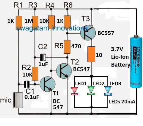
Please, I want a circuit diagram of running led light with bc547 and 3.7 v battery. Thank you in advance.
You can try the following circuit:
https://www.homemade-circuits.com/wp-content/uploads/2022/04/transistor-light-chaser-circuit.jpg
Your approache is very good how ever,
Road Stud Blinker circuit you have displayed looks to be practically not useful for commercial purpose .
As battery size is too high.
Can you post a circuit used in existing commercial Road Studs with blinking .
Vijay
Thank you so much, however i do not have the commercial version schematic, but I can provide a design using a single li-ion battery as shown below:
https://www.homemade-circuits.com/wp-content/uploads/2025/04/stud-light-4.2V.jpg
Want to buy PCB for rod stud light qty 100 Nos. i am starting manufacturing of rod stud, Moulds are ready, want to use 6 LED 3 mm size
Sorry, we don’t supply PCBs from this website.